EP0660284B1 - Infrared intruder detection system - Google Patents
Infrared intruder detection system Download PDFInfo
- Publication number
- EP0660284B1 EP0660284B1 EP94402892A EP94402892A EP0660284B1 EP 0660284 B1 EP0660284 B1 EP 0660284B1 EP 94402892 A EP94402892 A EP 94402892A EP 94402892 A EP94402892 A EP 94402892A EP 0660284 B1 EP0660284 B1 EP 0660284B1
- Authority
- EP
- European Patent Office
- Prior art keywords
- light
- window
- optical path
- obstruction
- acceptor
- Prior art date
- Legal status (The legal status is an assumption and is not a legal conclusion. Google has not performed a legal analysis and makes no representation as to the accuracy of the status listed.)
- Expired - Lifetime
Links
Images


Classifications
-
- G—PHYSICS
- G08—SIGNALLING
- G08B—SIGNALLING SYSTEMS, e.g. PERSONAL CALLING SYSTEMS; ORDER TELEGRAPHS; ALARM SYSTEMS
- G08B29/00—Checking or monitoring of signalling or alarm systems; Prevention or correction of operating errors, e.g. preventing unauthorised operation
- G08B29/02—Monitoring continuously signalling or alarm systems
- G08B29/04—Monitoring of the detection circuits
- G08B29/046—Monitoring of the detection circuits prevention of tampering with detection circuits
-
- Y—GENERAL TAGGING OF NEW TECHNOLOGICAL DEVELOPMENTS; GENERAL TAGGING OF CROSS-SECTIONAL TECHNOLOGIES SPANNING OVER SEVERAL SECTIONS OF THE IPC; TECHNICAL SUBJECTS COVERED BY FORMER USPC CROSS-REFERENCE ART COLLECTIONS [XRACs] AND DIGESTS
- Y10—TECHNICAL SUBJECTS COVERED BY FORMER USPC
- Y10S—TECHNICAL SUBJECTS COVERED BY FORMER USPC CROSS-REFERENCE ART COLLECTIONS [XRACs] AND DIGESTS
- Y10S250/00—Radiant energy
- Y10S250/01—Passive intrusion detectors
Definitions
- the present invention relates generally to an intruder detection system, and more particularly to a passive type intruder detection system for securing detection even if any obstruction intervenes between the detector and an intruder.
- An intruder detection system is commonly provided with a light receiving window having a light transmissive pane (hereinafter referred to as "window-pane") through which an acceptor receives infrared ray radiated by an intruder passing through a detection area.
- window-pane a light transmissive pane
- an intruder who knows the presence of a detection system deliberately covers the window with a non-transmissive material such as cloth so as to disable the detection system.
- Such an obstruction may inadvertently happen owing to wind or any other cause.
- an alarm will fail, an automatic door will not open, or no signal is transmitted to a contract security service.
- EP-A-499 177 discloses an intruder detection system for sensing infrared radiated by a human intruder through a window-pane and detecting the intrusion through the reception of an output from the infrared sensor, the system including a light emitter for projecting infrared ray toward a detection area, and a light acceptor for receiving at least part of the infrared ray projected by the light emitter through an obstruction detection optical path, the light emitter and the light acceptor being located in opposite positions with respect to the window.
- An object of the present invention is to provide an improved detection system of this kind, as claimed in the appending claim.
- a housing 1 includes a back plate 1A placeable on a wall and an eaves-like plate 1B projecting forward.
- the housing 1 is provided with a mounting plate 2 in parallel with the back plate 1A, and with a window-pane 3 made of a polyethylene sheet having a Fresnel lens 4 formed on the back thereof.
- a PIR (passive infrared photosensor) sensor is disposed at a focusing position of the Fresnel lens 4.
- the window-pane 3, the Fresnel lens 4 and the PIR sensor 5 constitute an intruder detection system.
- a light emitter 7 which consists of an infrared emitting diode is fixed to a lower end of the mounting plate 2, and a prism lens 8 disposed in front of the emitter 7.
- a light acceptor 9 which consists of an infrared receiving diode is fixed to an upper end of the mounting plate 2.
- the reference numeral 10 designates a reflecting mirror which reflects light from the light emitter 7 and allows it into the acceptor 9 as shown in Figure 3.
- the prism lens 8 includes a lens portion 82 for allowing light to pass straight therethrough and a prism portion 83 for allowing light to diagonally deflect upward.
- the infrared ray radiated by the intruder passes through the window-pane 3, and is focused by the Fresnel lens 4. Then it is received by the PIR sensor 5 which generates a signal.
- the light emitter 7 and prism lens 8 project light both in an open optical path (A) and a closed optical path (B). If no obstructive object intervenes in the optical path (A), the light is projected into the open optical path (A) and disperses without being received by the acceptor 9. Part of the light from the light emitter 7 is projected into the closed optical path (B), and after reflecting upon the mirror 10, it is incident to the acceptor 9.
- the path from the light emitter 7 to the light acceptor 9 through the reflecting mirror 10 constitutes an obstacle detection optical path 13, which are indicated by the arrows.
- An obstructive object 11 is placed at a distance from the window-pane 3 so that the PIR sensor 5 may fail to receive the infrared radiated by an intruder passing through the detection area.
- the light in the open optical path (A) reflects upon the obstructive object 11, and part of it is received by the acceptor 9, thereby increasing the amount of light received in the acceptor 9.
- An obstructive cover 11 is placed directly on the window-pane 3, so that the PIR sensor 5 fails to receive infrared radiated by an intruder passing through the detection area.
- the obstructive cover 11 also blocks the closed optical path (B), thereby decreasing the amount of light received in the acceptor 9.
- the light emitter 7 emits light upon reception of outputs of a pulse generator 12.
- the interval of time T is preferably 0.01 to 10 seconds.
- a short period of time T does not enhance the accuracy of detection but results in the consumption of electricity in emitting light constantly.
- a long period of time T is disadvantageous in that if an intruder stolen into the site immediately after the window is covered, the intruder cannot be detected by the PIR sensor 5.
- an alternative way is to inform a contract security service of the detection of an obstructive act as soon as it is detected.
- the acceptor 9 receives part of the light from the light emitter 7 that passes through the obstacle detection optical path 13.
- the output of the acceptor 9 is stepped up by an amplifier 14, and a peak value output of the amplifier 14 is held by a sample holding circuit 15 which is operated in synchronism with the pulse generator 12 and the pulse output.
- a window comparator 16 removes components existing between those at low level (Th-L) and at high-level (Th-H)
- the window comparator 16 outputs signals when any component above and below these levels are input.
- An output circuit 17 outputs an obstacle detection signal in response to the outputs of the window comparator 16.
- Figure 7(A) shows a waveform of the output of the pulse generator 12, and Figure 7(B) shows that of the amplifier 14 wherein the waveform indicated by 1 ⁇ is obtained when no obstruction is present, that indicated by 2 ⁇ is obtained when an incident light increases owing to the addition of a reflecting light from an obstacle object (Figure 4), and that indicated by 3 ⁇ is obtained when an incident light decreases owing to the presence of an obstacle ( Figure 4).
- Figure 7(C) shows the waveforms of outputs of the sample holding circuit 15, wherein those indicated by 1 ⁇ , 2 ⁇ , and 3 ⁇ correspond to those indicated by 1 ⁇ , 2 ⁇ , and 3 ⁇ .
- Figure 7(D) shows the waveforms of signals input to the window comparator 16 wherein the levels Th-H and Th-L are shown for the upper limit and lower limit.
- Figure 7(E) shows the waveforms of outputs of the window comparator 16 in correspondence to the states shown in Figure 7(D).
Landscapes
- Engineering & Computer Science (AREA)
- Computer Security & Cryptography (AREA)
- Physics & Mathematics (AREA)
- General Physics & Mathematics (AREA)
- Burglar Alarm Systems (AREA)
- Geophysics And Detection Of Objects (AREA)
- Photometry And Measurement Of Optical Pulse Characteristics (AREA)
Description
- The present invention relates generally to an intruder detection system, and more particularly to a passive type intruder detection system for securing detection even if any obstruction intervenes between the detector and an intruder.
- An intruder detection system is commonly provided with a light receiving window having a light transmissive pane (hereinafter referred to as "window-pane") through which an acceptor receives infrared ray radiated by an intruder passing through a detection area. It may happen that an intruder who knows the presence of a detection system deliberately covers the window with a non-transmissive material such as cloth so as to disable the detection system. Such an obstruction may inadvertently happen owing to wind or any other cause. As a result, an alarm will fail, an automatic door will not open, or no signal is transmitted to a contract security service.
- Accordingly, there is a need for a passive type intruder detection system capable of securing the detection of an intruder even if the window is deliberately or inadvertently covered with a non-transmissive material.
- Such a system is known from EP-A-499 177 which discloses an intruder detection system for sensing infrared radiated by a human intruder through a window-pane and detecting the intrusion through the reception of an output from the infrared sensor, the system including a light emitter for projecting infrared ray toward a detection area, and a light acceptor for receiving at least part of the infrared ray projected by the light emitter through an obstruction detection optical path, the light emitter and the light acceptor being located in opposite positions with respect to the window.
- Thus, even if a light absorptive cover is placed directly on the window-pane or at a distance therefrom, the intrusion detection is secured.
- An object of the present invention is to provide an improved detection system of this kind, as claimed in the appending claim.
-
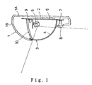
- Figure 1 is a view, vertically in cross-section, of an optical section incorporated in the intrusion detection system according to the present invention;
- Figure 2(A) is a front view showing a prism lens on an enlarged scale shown in Figure 1;
- Figure 2(B) is a cross-sectional view taken along the line c-c in Figure 2(A);
- Figure 3 is an explanatory view exemplifying an optical action performed by the embodiment shown in Figure 1;
- Figure 4 is an explanatory view exemplifying an optical action performed by an obstructive act;
- Figure 5 is an explanatory view exemplifying an optical action performed by another type of obstructive act;
- Figure 6 is a block diagram showing an electric circuit for detecting an obstructive act; and
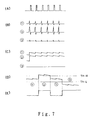
- Figures 7(A) to 7(E) are diagrammatic views showing the actions of the electric circuit shown in Figure 6.
-
- Referring to Figures 1 to 3, the exemplary detection system is designed to be placed on a wall. A
housing 1 includes aback plate 1A placeable on a wall and an eaves-like plate 1B projecting forward. Thehousing 1 is provided with amounting plate 2 in parallel with theback plate 1A, and with a window-pane 3 made of a polyethylene sheet having a Fresnel lens 4 formed on the back thereof. A PIR (passive infrared photosensor) sensor is disposed at a focusing position of the Fresnel lens 4. The window-pane 3, the Fresnel lens 4 and thePIR sensor 5 constitute an intruder detection system. - A
light emitter 7 which consists of an infrared emitting diode is fixed to a lower end of themounting plate 2, and aprism lens 8 disposed in front of theemitter 7. Alight acceptor 9 which consists of an infrared receiving diode is fixed to an upper end of themounting plate 2. Thereference numeral 10 designates a reflecting mirror which reflects light from thelight emitter 7 and allows it into theacceptor 9 as shown in Figure 3. - As shown in Figure 2(A), the
prism lens 8 includes alens portion 82 for allowing light to pass straight therethrough and aprism portion 83 for allowing light to diagonally deflect upward. - Referring to Figure 3, the optical action of the exemplary system will be described:
- If an intruder passes through a detection area, the infrared ray radiated by the intruder passes through the window-
pane 3, and is focused by the Fresnel lens 4. Then it is received by thePIR sensor 5 which generates a signal. Thelight emitter 7 andprism lens 8 project light both in an open optical path (A) and a closed optical path (B). If no obstructive object intervenes in the optical path (A), the light is projected into the open optical path (A) and disperses without being received by theacceptor 9. Part of the light from thelight emitter 7 is projected into the closed optical path (B), and after reflecting upon themirror 10, it is incident to theacceptor 9. The path from thelight emitter 7 to thelight acceptor 9 through the reflectingmirror 10 constitutes an obstacle detectionoptical path 13, which are indicated by the arrows. - Referring to Figure 4, a counteraction against an obstructive act will be described:
- An
obstructive object 11 is placed at a distance from the window-pane 3 so that thePIR sensor 5 may fail to receive the infrared radiated by an intruder passing through the detection area. The light in the open optical path (A) reflects upon theobstructive object 11, and part of it is received by theacceptor 9, thereby increasing the amount of light received in theacceptor 9. - Referring to Figure 5, a counteraction in response to another type of obstructive act intended to directly cover the window-pane 3:
- An
obstructive cover 11 is placed directly on the window-pane 3, so that thePIR sensor 5 fails to receive infrared radiated by an intruder passing through the detection area. Theobstructive cover 11 also blocks the closed optical path (B), thereby decreasing the amount of light received in theacceptor 9. - Referring to Figure 6, the
light emitter 7 emits light upon reception of outputs of apulse generator 12. The interval of time T is preferably 0.01 to 10 seconds. A short period of time T does not enhance the accuracy of detection but results in the consumption of electricity in emitting light constantly. A long period of time T is disadvantageous in that if an intruder stole into the site immediately after the window is covered, the intruder cannot be detected by thePIR sensor 5. In this case, an alternative way is to inform a contract security service of the detection of an obstructive act as soon as it is detected. Theacceptor 9 receives part of the light from thelight emitter 7 that passes through the obstacle detectionoptical path 13. The output of theacceptor 9 is stepped up by anamplifier 14, and a peak value output of theamplifier 14 is held by asample holding circuit 15 which is operated in synchronism with thepulse generator 12 and the pulse output. Awindow comparator 16 removes components existing between those at low level (Th-L) and at high-level (Th-H) - In this way, the
window comparator 16 outputs signals when any component above and below these levels are input. Anoutput circuit 17 outputs an obstacle detection signal in response to the outputs of thewindow comparator 16. - Referring to Figure 7, various waveforms of signals will be explained:
- Figure 7(A) shows a waveform of the output of the
pulse generator 12, and Figure 7(B) shows that of theamplifier 14 wherein the waveform indicated by 1 ○ is obtained when no obstruction is present, that indicated by 2 ○ is obtained when an incident light increases owing to the addition of a reflecting light from an obstacle object (Figure 4), and that indicated by 3 ○ is obtained when an incident light decreases owing to the presence of an obstacle (Figure 4). Figure 7(C) shows the waveforms of outputs of thesample holding circuit 15, wherein those indicated by 1 ○, 2 ○, and 3 ○ correspond to those indicated by 1 ○, 2 ○, and 3 ○. - Figure 7(D) shows the waveforms of signals input to the
window comparator 16 wherein the levels Th-H and Th-L are shown for the upper limit and lower limit. Figure 7(E) shows the waveforms of outputs of thewindow comparator 16 in correspondence to the states shown in Figure 7(D).
Claims (1)
- An intruder detection system for sensing infrared radiated by a human intruder through a window (3) of the system and detecting the intrusion through the reception of an output from the infrared sensor (5), the system comprising :characterized in that a prism lens (8) comprising a prism portion (83) and a lens portion (82) is interposed between the light emitter (7) and the window (3) so as to guide the light projected by the light emitter (7) into the first and second optical paths (A, B), respectively.a light emitter (7) provided outside the window (3) so as to project infrared ray toward a detection area ;a light acceptor (9) provided inside the window (3) ;wherein the light emitter (7) projects light into a first optical path (A) that extends to a detection area and a second optical path (B), the light in the second path (B) being partly directed into an obstruction detection optical path (13) for detecting an obstructive object (11) which directly or indirectly covers the window (3), anda window comparator (16) which compares an output of the light acceptor (9) with a high-level output value thereof which is previously obtained when no obstruction intervenes the first optical path (A) as well as a low-level output value thereof which is previously obtained when no obstruction intervenes the second optical path (B), whereby the comparator (16) detects the presence of obstruction within the detection area when the light acceptor output is above the high-level output value, whereas it detects the presence of obstruction on the outer surface of or in the neighbourhood of the window (3) when the output is below the low-level output value,
Applications Claiming Priority (3)
| Application Number | Priority Date | Filing Date | Title |
|---|---|---|---|
| JP32153793 | 1993-12-21 | ||
| JP5321537A JP2983423B2 (en) | 1993-12-21 | 1993-12-21 | Infrared human body detector |
| JP321537/93 | 1993-12-21 |
Publications (2)
| Publication Number | Publication Date |
|---|---|
| EP0660284A1 EP0660284A1 (en) | 1995-06-28 |
| EP0660284B1 true EP0660284B1 (en) | 2002-03-13 |
Family
ID=18133671
Family Applications (1)
| Application Number | Title | Priority Date | Filing Date |
|---|---|---|---|
| EP94402892A Expired - Lifetime EP0660284B1 (en) | 1993-12-21 | 1994-12-15 | Infrared intruder detection system |
Country Status (4)
| Country | Link |
|---|---|
| US (1) | US5489892A (en) |
| EP (1) | EP0660284B1 (en) |
| JP (1) | JP2983423B2 (en) |
| DE (1) | DE69430113T2 (en) |
Cited By (1)
| Publication number | Priority date | Publication date | Assignee | Title |
|---|---|---|---|---|
| CN101228564B (en) * | 2005-06-28 | 2010-05-12 | 罗伯特·博世有限公司 | Sensor device for checking liquid on surface |
Families Citing this family (22)
| Publication number | Priority date | Publication date | Assignee | Title |
|---|---|---|---|---|
| IL119372A (en) * | 1995-11-03 | 2000-02-17 | Siemens Building Tech Ag | Passive infrared intruder detector |
| EP0772171B1 (en) * | 1995-11-03 | 2003-01-08 | Siemens Building Technologies AG | Passive intrusion detector and its use |
| NL1003500C2 (en) * | 1996-07-04 | 1998-01-07 | Aritech Bv | Monitoring system with light-guiding means. |
| DE19737166C2 (en) * | 1997-08-26 | 2002-04-25 | Esser Security Systems Gmbh | PIR |
| JP3695096B2 (en) * | 1997-10-20 | 2005-09-14 | アツミ電氣株式会社 | Hot wire sensor |
| US6031456A (en) * | 1998-05-13 | 2000-02-29 | Nippon Aleph Corporation | Detector |
| US6034602A (en) * | 1998-09-08 | 2000-03-07 | Quibodeaux; Stephan Brice | Computer monitor switch |
| EP1061489B1 (en) * | 1999-06-07 | 2004-08-25 | Siemens Building Technologies AG | Intrusion detector with a device for monitoring against tampering |
| JP3899207B2 (en) * | 1999-07-06 | 2007-03-28 | セコム株式会社 | Image sensor |
| JP2001228020A (en) * | 2000-02-18 | 2001-08-24 | Optex Co Ltd | Crime prevention sensor with obstruction detecting function |
| JP2001229473A (en) * | 2000-02-18 | 2001-08-24 | Optex Co Ltd | Crime-preventive sensor with disturbance detecting function |
| NL1019039C2 (en) * | 2001-09-26 | 2003-03-27 | Interlogix B V | Surveillance detector. |
| US7045764B2 (en) | 2002-10-17 | 2006-05-16 | Rite-Hite Holding Corporation | Passive detection system for detecting a body near a door |
| US7034682B2 (en) | 2003-06-20 | 2006-04-25 | Rite-Hite Holding Corporation | Door with a safety antenna |
| JP2005241556A (en) | 2004-02-27 | 2005-09-08 | Optex Co Ltd | Passive-type infrared detector and obstruction detection system used therefor |
| RU2292598C2 (en) * | 2004-09-21 | 2007-01-27 | Закрытое акционерное общество "РИЭЛТА" | Guard electro-optical passive infrared annunciator provided with device for detecting masking of object |
| EP1989695B1 (en) | 2006-02-20 | 2013-04-24 | Robert Bosch GmbH | Obstruction detection device |
| ES2337178T3 (en) | 2006-03-16 | 2010-04-21 | Robert Bosch Gmbh | DEVICE FOR INFRARED INTRUSION DETECTION. |
| JP4915657B2 (en) * | 2006-12-21 | 2012-04-11 | オプテックス株式会社 | Non-contact switch for automatic door |
| JP5902006B2 (en) * | 2012-03-09 | 2016-04-13 | 株式会社メガチップス | Surveillance camera |
| JP7397266B2 (en) * | 2019-10-25 | 2023-12-13 | 竹中エンジニアリング株式会社 | Detection device with visual field obstruction monitoring function |
| CN114387749B (en) * | 2021-12-30 | 2024-08-02 | 杭州海康威视数字技术股份有限公司 | Intrusion detector |
Family Cites Families (5)
| Publication number | Priority date | Publication date | Assignee | Title |
|---|---|---|---|---|
| US4242669A (en) * | 1979-05-04 | 1980-12-30 | B. A. Security Systems Limited | Passive infrared intruder detection system |
| GB8829892D0 (en) * | 1988-12-22 | 1989-09-13 | Racal Guardall Scotland | Radiation detection arrangements and methods |
| IT1241278B (en) * | 1990-10-19 | 1993-12-29 | Elkron Spa | ANTI-BLINDING DEVICE FOR COMPONENTS OF SECURITY SYSTEMS. |
| IT1245405B (en) * | 1991-02-11 | 1994-09-20 | Bitron Video | ANTI-INTRUSION DEVICE |
| NL9200283A (en) * | 1992-02-17 | 1993-09-16 | Aritech Bv | MONITORING SYSTEM. |
-
1993
- 1993-12-21 JP JP5321537A patent/JP2983423B2/en not_active Expired - Fee Related
-
1994
- 1994-12-06 US US08/350,289 patent/US5489892A/en not_active Expired - Lifetime
- 1994-12-15 DE DE69430113T patent/DE69430113T2/en not_active Expired - Fee Related
- 1994-12-15 EP EP94402892A patent/EP0660284B1/en not_active Expired - Lifetime
Cited By (1)
| Publication number | Priority date | Publication date | Assignee | Title |
|---|---|---|---|---|
| CN101228564B (en) * | 2005-06-28 | 2010-05-12 | 罗伯特·博世有限公司 | Sensor device for checking liquid on surface |
Also Published As
| Publication number | Publication date |
|---|---|
| US5489892A (en) | 1996-02-06 |
| DE69430113T2 (en) | 2002-08-29 |
| JPH07174622A (en) | 1995-07-14 |
| EP0660284A1 (en) | 1995-06-28 |
| DE69430113D1 (en) | 2002-04-18 |
| JP2983423B2 (en) | 1999-11-29 |
Similar Documents
| Publication | Publication Date | Title |
|---|---|---|
| US5489892A (en) | Infrared human detector not barred by an intervening obstruction | |
| EP0556898B2 (en) | Intrusion alarm system | |
| EP1126430B2 (en) | Security sensor having disturbance detecting capability | |
| US6469625B1 (en) | Security sensor having disturbance detecting capability | |
| US5506567A (en) | Process for monitoring the openings to an enclosed space | |
| US4752768A (en) | Intruder detector with anti-obscuring means | |
| JP3086406B2 (en) | Passive infrared human body detector | |
| EP0472039B1 (en) | Fire detecting method and device | |
| CA2143156A1 (en) | Control device and process for the contactless control of a unit, especially a plumbing unit | |
| EP0481934A1 (en) | An anti-masking device for security systems | |
| GB2411468A (en) | Passive infrared sensor with obstruction detection | |
| EP0499177A1 (en) | Anti-intrusion device | |
| US6262661B1 (en) | Passive infrared detector | |
| US6031456A (en) | Detector | |
| JP3840502B2 (en) | Security sensor with interference detection function using stray light | |
| JPH1186152A (en) | Security sensor having obstruction-detecting function equipped with optical fiber | |
| JPH0430552Y2 (en) | ||
| KR100339255B1 (en) | infrared sensor and managing method thereof | |
| JP4568821B2 (en) | Security sensor with interference detection function | |
| RU2292598C2 (en) | Guard electro-optical passive infrared annunciator provided with device for detecting masking of object | |
| JP3025221U (en) | Infrared security alarm device | |
| JPS6031078A (en) | Detection of matter in opening part of building | |
| JP2521505B2 (en) | Passive infrared security sensor with visual field obstruction monitoring mechanism | |
| RU18783U1 (en) | ADAPTIVE OPTICAL SIGNALING DEVICE | |
| JP2005036476A (en) | Opening door detection device and crime prevention system |
Legal Events
| Date | Code | Title | Description |
|---|---|---|---|
| PUAI | Public reference made under article 153(3) epc to a published international application that has entered the european phase |
Free format text: ORIGINAL CODE: 0009012 |
|
| AK | Designated contracting states |
Kind code of ref document: A1 Designated state(s): CH DE FR GB LI |
|
| 17P | Request for examination filed |
Effective date: 19951016 |
|
| 17Q | First examination report despatched |
Effective date: 19990218 |
|
| RTI1 | Title (correction) |
Free format text: INFRARED INTRUDER DETECTION SYSTEM |
|
| GRAG | Despatch of communication of intention to grant |
Free format text: ORIGINAL CODE: EPIDOS AGRA |
|
| RTI1 | Title (correction) |
Free format text: INFRARED INTRUDER DETECTION SYSTEM |
|
| GRAG | Despatch of communication of intention to grant |
Free format text: ORIGINAL CODE: EPIDOS AGRA |
|
| GRAG | Despatch of communication of intention to grant |
Free format text: ORIGINAL CODE: EPIDOS AGRA |
|
| GRAH | Despatch of communication of intention to grant a patent |
Free format text: ORIGINAL CODE: EPIDOS IGRA |
|
| GRAH | Despatch of communication of intention to grant a patent |
Free format text: ORIGINAL CODE: EPIDOS IGRA |
|
| REG | Reference to a national code |
Ref country code: GB Ref legal event code: IF02 |
|
| GRAA | (expected) grant |
Free format text: ORIGINAL CODE: 0009210 |
|
| AK | Designated contracting states |
Kind code of ref document: B1 Designated state(s): CH DE FR GB LI |
|
| REG | Reference to a national code |
Ref country code: CH Ref legal event code: EP |
|
| REG | Reference to a national code |
Ref country code: CH Ref legal event code: NV Representative=s name: TROESCH SCHEIDEGGER WERNER AG |
|
| REF | Corresponds to: |
Ref document number: 69430113 Country of ref document: DE Date of ref document: 20020418 |
|
| ET | Fr: translation filed | ||
| PLBE | No opposition filed within time limit |
Free format text: ORIGINAL CODE: 0009261 |
|
| STAA | Information on the status of an ep patent application or granted ep patent |
Free format text: STATUS: NO OPPOSITION FILED WITHIN TIME LIMIT |
|
| 26N | No opposition filed |
Effective date: 20021216 |
|
| PGFP | Annual fee paid to national office [announced via postgrant information from national office to epo] |
Ref country code: DE Payment date: 20090112 Year of fee payment: 15 |
|
| PGFP | Annual fee paid to national office [announced via postgrant information from national office to epo] |
Ref country code: GB Payment date: 20081219 Year of fee payment: 15 Ref country code: CH Payment date: 20090113 Year of fee payment: 15 |
|
| PGFP | Annual fee paid to national office [announced via postgrant information from national office to epo] |
Ref country code: FR Payment date: 20081231 Year of fee payment: 15 |
|
| REG | Reference to a national code |
Ref country code: CH Ref legal event code: PL |
|
| GBPC | Gb: european patent ceased through non-payment of renewal fee |
Effective date: 20091215 |
|
| REG | Reference to a national code |
Ref country code: FR Ref legal event code: ST Effective date: 20100831 |
|
| PG25 | Lapsed in a contracting state [announced via postgrant information from national office to epo] |
Ref country code: LI Free format text: LAPSE BECAUSE OF NON-PAYMENT OF DUE FEES Effective date: 20091231 Ref country code: FR Free format text: LAPSE BECAUSE OF NON-PAYMENT OF DUE FEES Effective date: 20091231 Ref country code: CH Free format text: LAPSE BECAUSE OF NON-PAYMENT OF DUE FEES Effective date: 20091231 |
|
| PG25 | Lapsed in a contracting state [announced via postgrant information from national office to epo] |
Ref country code: DE Free format text: LAPSE BECAUSE OF NON-PAYMENT OF DUE FEES Effective date: 20100701 |
|
| PG25 | Lapsed in a contracting state [announced via postgrant information from national office to epo] |
Ref country code: GB Free format text: LAPSE BECAUSE OF NON-PAYMENT OF DUE FEES Effective date: 20091215 |