EP0660133A2 - Falschradarspurenunterscheidung in Nebenzipfeln von Monopulsantennen - Google Patents
Falschradarspurenunterscheidung in Nebenzipfeln von Monopulsantennen Download PDFInfo
- Publication number
- EP0660133A2 EP0660133A2 EP94309116A EP94309116A EP0660133A2 EP 0660133 A2 EP0660133 A2 EP 0660133A2 EP 94309116 A EP94309116 A EP 94309116A EP 94309116 A EP94309116 A EP 94309116A EP 0660133 A2 EP0660133 A2 EP 0660133A2
- Authority
- EP
- European Patent Office
- Prior art keywords
- monopulse
- target
- sum
- ratio
- sidelobe
- Prior art date
- Legal status (The legal status is an assumption and is not a legal conclusion. Google has not performed a legal analysis and makes no representation as to the accuracy of the status listed.)
- Granted
Links
Images


Classifications
-
- G—PHYSICS
- G01—MEASURING; TESTING
- G01S—RADIO DIRECTION-FINDING; RADIO NAVIGATION; DETERMINING DISTANCE OR VELOCITY BY USE OF RADIO WAVES; LOCATING OR PRESENCE-DETECTING BY USE OF THE REFLECTION OR RERADIATION OF RADIO WAVES; ANALOGOUS ARRANGEMENTS USING OTHER WAVES
- G01S13/00—Systems using the reflection or reradiation of radio waves, e.g. radar systems; Analogous systems using reflection or reradiation of waves whose nature or wavelength is irrelevant or unspecified
- G01S13/02—Systems using reflection of radio waves, e.g. primary radar systems; Analogous systems
- G01S13/06—Systems determining position data of a target
- G01S13/42—Simultaneous measurement of distance and other co-ordinates
- G01S13/44—Monopulse radar, i.e. simultaneous lobing
- G01S13/4418—Monopulse radar, i.e. simultaneous lobing with means for eliminating radar-dependent errors in angle measurements, e.g. multipath effects
-
- G—PHYSICS
- G01—MEASURING; TESTING
- G01S—RADIO DIRECTION-FINDING; RADIO NAVIGATION; DETERMINING DISTANCE OR VELOCITY BY USE OF RADIO WAVES; LOCATING OR PRESENCE-DETECTING BY USE OF THE REFLECTION OR RERADIATION OF RADIO WAVES; ANALOGOUS ARRANGEMENTS USING OTHER WAVES
- G01S13/00—Systems using the reflection or reradiation of radio waves, e.g. radar systems; Analogous systems using reflection or reradiation of waves whose nature or wavelength is irrelevant or unspecified
- G01S13/66—Radar-tracking systems; Analogous systems
- G01S13/68—Radar-tracking systems; Analogous systems for angle tracking only
- G01S13/685—Radar-tracking systems; Analogous systems for angle tracking only using simultaneous lobing techniques
-
- G—PHYSICS
- G01—MEASURING; TESTING
- G01S—RADIO DIRECTION-FINDING; RADIO NAVIGATION; DETERMINING DISTANCE OR VELOCITY BY USE OF RADIO WAVES; LOCATING OR PRESENCE-DETECTING BY USE OF THE REFLECTION OR RERADIATION OF RADIO WAVES; ANALOGOUS ARRANGEMENTS USING OTHER WAVES
- G01S7/00—Details of systems according to groups G01S13/00, G01S15/00, G01S17/00
- G01S7/02—Details of systems according to groups G01S13/00, G01S15/00, G01S17/00 of systems according to group G01S13/00
- G01S7/28—Details of pulse systems
- G01S7/2813—Means providing a modification of the radiation pattern for cancelling noise, clutter or interfering signals, e.g. side lobe suppression, side lobe blanking, null-steering arrays
Definitions
- This invention relates to monopulse tracking radars, and more particularly to a technique for preventing sidelobe monopulse tracking.
- Counter-battery radars are used to track incoming artillery shells or mortar rounds.
- the target radar cross section (RCS) of an artillery shell or a mortar round is usually in the range of -22 dBsm (square meter) to -40 dBsm.
- An aircraft which has an RCS between +14 dBsm and -10 dBsm can fall in the sidelobe region of the radar antenna and produce a signal strength similar to a true artillery shell or mortar round target tracked by the main beam monopulse.
- sidelobe blanking systems which utilize a low-gain omnidirectional antenna operating in conjunction with the sum beam. Signals from both antennas are fed to separate receivers and their outputs compared. Any comparisons showing greater power level in the low gain channel are canceled, thus eliminating returns from those sectors of the sum beam having gain levels less than the omnidirectional antenna.
- a gain control in the omnidirectional antenna channel is required for adjusting the degree of sidelobe blanking.
- the disadvantages of the sidelobe blanking system are: (1) it requires an additional omnidirectional antenna and a receiver channel, (2) gain control between the receiver channels has to be checked periodically to ensure no faulty results due to receiver gain variation over time, and (3) additional antenna and receiver hardware are difficult to fit to the existing form factor and radar platform. This invention eliminates these disadvantages.
- This invention includes a method for discriminating against false sidelobe tracking in a monopulse radar system, wherein monopulse main and sidelobe beams are formed.
- the invention exploits the characteristic that the main beam monopulse is considerably wider than the sidelobe monopulse.
- the method comprises the following steps: forming first monopulse sum and difference beams pointing at a first beam pointing angle; processing the first monopulse beams to detect a potential target track at an approximate potential target angle; calculating a first ratio of the first difference beam and the first sum beam at the first beam target angle; forming second and third monopulse sum and difference beams at respective second and third beam pointing angles offset from the first pointing angle; processing the second and third monopulse beams to detect second and third beam potential target tracks corresponding to the first beam target track; calculating a second ratio of the second difference beam and the second sum beam; calculating a third ratio of the third difference beam and the third sum beam; and accepting or rejecting the potential target track as a true target track in dependence on characteristics of the first, second and third ratios.
- the second and third beam pointing angles are selected in dependence on a power value calculated from the first ratio.
- the second and third beams are selected as offset angles from the first pointing angle and toward the target if the power value equals or exceeds a predetermined threshold.
- the step of accepting or rejecting the track comprises accepting the potential target as a true target track only if magnitudes of the first, second and third ratios decrease monotonically from the first ratio to said second ratio, and from the second ratio to the third ratio, and rejecting the potential target if the magnitudes do not decrease monotonically.
- the characteristics of the ratios can further include the signs of the ratios, and the step of accepting or rejecting the track comprises accepting the potential target as a true target track only if the signs of the respective ratios are the same, and rejecting the potential target if the signs are not the same.
- the second and third beams are selected as offset angles from the first pointing angle and away from the estimated target angle.
- the step of accepting or rejecting the track comprises accepting the potential target as a true target track only if magnitudes of the first, second and third ratios increase monotonically from the first ratio to the second ratio, and from the second ratio to the third ratio, and rejecting the potential target if the magnitudes do not increase monotonically.
- the characteristics of the ratios can further include the sings of the ratios, and the step of accepting or rejecting the track comprises accepting the potential target as a true target track only if the signs of the respective ratios are the same, and rejecting the potential target if the signs are not the same.
- FIG. 1 illustrates an exemplary monopulse pattern, showing antenna elevation difference beam and sum beam patterns.
- FIG. 2 shows a delta/sum ratio pattern from the monopulse pattern of FIG. 1.
- FIG. 3 is a flow chart illustrating a method in accordance with the invention for discriminating false sidelobe tracks.
- FIGS. 4 and 5 show overlays of the exemplary main beam monopulse splitting pattern (solid line) and the sidelobe monopulse beam splitting pattern (dotted line).
- FIG. 6 is a block diagram of an exemplary monopulse radar system which can be programmed to perform the method of FIG. 3.
- FIG. 7 is a flow diagram illustrating a generalized method in accordance with the invention.
- a monopulse antenna system including systems using phased array antennas or reflector antennas, develops a sum beam and a difference beam.
- the target is normally tracked in the main beam area.
- there are other sidelobe sectors outside the main beam that can form a pattern similar to the monopulse characteristics but with lower antenna gain.
- a typical monopulse pattern is shown in FIG. 1.
- the main beam is pointing to 1.65° and a monopulse pattern is formed at that angle. Careful examination of this figure reveals that several monopulse patterns are formed in the sidelobe region at +5.8°, +6.9°, +8.7°, and other places.
- This invention uses a new approach to discriminate the false tracks in the sidelobe region.
- a delta-over-sum ( ⁇ / ⁇ ) pattern of FIG. 1 is plotted in FIG. 2 to show the beam splitting characteristics of the monopulse.
- the monopulse beam splitting characteristics provide measured target position in azimuth and elevation direction cosine space relative to the antenna.
- the monopulse beam splitting curve as shown in FIG. 2 is usually approximated by a cubic function and used in radar computers to estimate target position in azimuth and elevation. At 1.65° the width of the main beam monopulse is about 4.6°, while the width of the sidelobe monopulse is less than 1.8°.
- the false tracks in the sidelobe region can be discriminated by pointing the beam to two additional angles and then matching the amplitude of ⁇ / ⁇ measurements to the slope of the main beam monopulse curve shown in FIG. 2. If the ⁇ / ⁇ measurements fail to match the slope, then the target is in the sidelobe region and can be eliminated from the track report.
- FIG. 3 An exemplary algorithm to discriminate false sidelobe tracks in accordance with the invention is illustrated in the flow chart of FIG. 3.
- the magnitude of the first delta-over-sum ( ⁇ / ⁇ ) measurement determines which branch of the algorithm will be used. If the value of 20 log
- the estimated target angle of the first beam is derived from the beam splitting characteristic curve based on the sign and the value of the ( ⁇ / ⁇ )1 output.
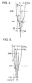
- the initial beam is beam #1, and the two additional beams are beams #2 and #3. If the target is in the sidelobe region, then it is very likely the target will fall on the opposite side of the monopulse slope as shown in FIG. 4.
- FIG. 4 shows two ( ⁇ / ⁇ ) beam splitting slopes. The wider monopulse is the main beam while the narrower monopulse is the sidelobe.
- the beams are moved toward the target by (1/3) ⁇ and (3/4) ⁇ , the target position moves from A to B to C on the main beam monopulse. However, the same beam movement will move the target from A' to B' and C' on the sidelobe monopulse.
- FIG. 5 shows the target locations of the main beam and sidelobe monopulse slopes.
- Point B' is on the opposite slope of the next monopulse and hence ( ⁇ / ⁇ )2 has a sign change. This enables discrimination of the false tracks in the sidelobe region.
- An additional ( ⁇ / ⁇ ) magnitude test is also added to check the relative amplitude of the initial beam and two additional beams. If
- FIG. 3 illustrates a logic flow diagram of the algorithm 20.
- a monopulse beam is formed which is directed at a first pointing angle.
- the power in dB of the difference/sum beam ratio is determined and compared to 0 dB. If this power is greater than or equal to 0 dB, operation branches to step 26. If the measured power is less than 0 dB, operation branches to step 40. If operation has branched to step 26, two new monopulse beams are formed, at (1/3) ⁇ and (3/4) ⁇ from the first beam angle toward the target, where ⁇ is the estimated target angle. The difference/sum beam ratio is measured at each new pointing angle.
- the signs of the delta/sum ratio in each of the three beams are compared to determine if there are any sign changes. If there was a sign change, the target is rejected (step 30), and the algorithm exited. If there was no sign change, then the magnitudes of the difference/sum ratios for the three beams are compared. If the magnitudes of beam 1, beam 2 and beam 3 decrease monotonically, then the track is accepted as a target track (step 36) and the algorithm exited; if the magnitudes do not decrease monotonically, the target is rejected (step 34) and the algorithm exited.
- step 40 if the power level of the difference/sum ratio does not exceed 0 dB, then operation branches to step 40. For this smaller signal, two beams are formed which are pointed away from the target at the first pointing angle by 0.2 ⁇ 3 and 0.65 ⁇ 3, where ⁇ 3 is the 3 dB beamwidth of the sum beam.
- the signs of the ratios of the difference/sum beams are compared. If there is a sign change among these ratios, then the target is rejected as a false track (step 44), and the algorithm is exited. If there is no sign change, then the magnitudes of the difference/sum ratios are compared to determine if magnitudes increase monotonically from beam 1 to beam 2 to beam 3. If not, the target is rejected at step 48; if so, the track is accepted as a valid target track at step 36, and the algorithm is exited.
- FIG. 6 is a simplified block diagram illustrative of a monopulse radar system 100 which may be programmed to carry out the algorithm of FIG. 3.
- the system includes an antenna section 110, a transceiver section 130, a signal distribution section 150 and a processing section 160.
- the antenna section 110 includes the antenna 112, which is coupled to a duplexer 114 to separate the transmitter and received signals. Antenna received signals from the duplexer 114 and directly from the antenna 112 are directed to an RF detector and amplifier 116, and sum, difference azimuth and difference elevation signal are sent via a rotary joint 118 mounted on the antenna pedestal 120 to the receiver 136.
- a beam steering unit 122 controls the steering of beams formed by the antenna 112, and interfaces through a slip ring assembly 124 with the signal distribution function 152 of section 150.
- An azimuth encoder 126 provides encoder data to the section 152 which indicates the azimuth position of the antenna pedestal.
- the transceiver section 130 includes the radar exciter 132, the transmitter 134 which receives the RF drive signal from the exciter and provides the high power transmit signal through a waveguide switch 138 to the rotary joint and the duplexer to the antenna.
- the receiver 136 in this embodiment provides a third IF signal to the radar signal and control processor 162, from which the signals used to perform the algorithm can be derived.
- the processor section 160 includes the processor 162, a computer 164, manual data entry device 166 and a data storage device 168. Operational commands can be provided to the processor 162, and data from the processor 162 can be provided to the computer.
- the processor section 160 is programmed to carry out the algorithm of FIG. 3.
- the second and third beams are electronically steered.
- this invention can also be applied to multiple feed horn reflector antennas which use physical rotation to point the second and third beams.
- the system 100 is, in terms of the general hardware elements shown in FIG. 6, of a conventional design.
- the processor 162 and/or computer 164 can be programmed to perform the algorithm of FIG. 3.
- conventional monopulse radars can be readily modified to include the invention, simply by modifying the software performed by the processor elements of the system.
- FIG. 7 is a simplfied flow diagram illustrating a method 50 for operating the monopulse radar system 100 in accordance with the invention.
- the monopulse radar system is operated in the conventional manner to form first monopulse sum and difference beams point at a first beam pointing angle.
- the first monopulse beams are processed to detect a potential target track at approximate potential target angles. The foregoing steps are conventional, and are performed by a conventional monopulse radar system.
- a first ratio is calculated, of the ratio of the first difference beam to the first sum beam at the potential target angle.
- second and third monopulse beams are formed at respective second and third pointing angles, which are selected as described above regarding FIG. 3.
- Second and third monopulse beams are processed (step 60) to detect second and third beam potential target tracks corresponding to the first beam target track.
- Second and third ratios are calculated of the respective second and third difference and sum beams (steps 62, 64).
- the potential target track is then accepted or rejected in dependence on characteristics of the first, second and third ratios (step 66). As discussed above, e.g. regarding FIG. 3, these characteristics include the signs of the ratios and their magnitudes.
- the application of this method is not limited to phased array antennas.
- a typical reflector type of monopulse antenna has a similar sidelobe tracking problem. This technique can be used to solve the sidelobe tracking problem for the reflector type of antenna system.
- This invention is applicable to radar systems designed to track low observable targets such as missiles and artillery shells to discriminate false tracks in the sidelobe region.
Landscapes
- Engineering & Computer Science (AREA)
- Radar, Positioning & Navigation (AREA)
- Remote Sensing (AREA)
- Computer Networks & Wireless Communication (AREA)
- Physics & Mathematics (AREA)
- General Physics & Mathematics (AREA)
- Radar Systems Or Details Thereof (AREA)
Applications Claiming Priority (2)
| Application Number | Priority Date | Filing Date | Title |
|---|---|---|---|
| US173301 | 1993-12-23 | ||
| US08/173,301 US5400035A (en) | 1993-12-23 | 1993-12-23 | False track discrimination in the sidelobe region of a monopulse antenna |
Publications (3)
| Publication Number | Publication Date |
|---|---|
| EP0660133A2 true EP0660133A2 (de) | 1995-06-28 |
| EP0660133A3 EP0660133A3 (de) | 1996-07-17 |
| EP0660133B1 EP0660133B1 (de) | 2001-10-24 |
Family
ID=22631398
Family Applications (1)
| Application Number | Title | Priority Date | Filing Date |
|---|---|---|---|
| EP94309116A Expired - Lifetime EP0660133B1 (de) | 1993-12-23 | 1994-12-07 | Falschradarspurenunterscheidung in Nebenzipfeln von Monopulsantennen |
Country Status (4)
| Country | Link |
|---|---|
| US (1) | US5400035A (de) |
| EP (1) | EP0660133B1 (de) |
| DE (1) | DE69428766T2 (de) |
| IL (1) | IL111649A (de) |
Families Citing this family (9)
| Publication number | Priority date | Publication date | Assignee | Title |
|---|---|---|---|---|
| EP0942294A3 (de) * | 1998-03-09 | 2000-06-07 | Siemens Schweiz AG (Siemens Suisse SA) (Siemens Svizzera SA) Siemens Switzerland Ltd) | Verfahren zur Seitenkeulenunterdrückung und Amplituden- oder Phasen-Monopulsradargerät |
| DE60027418T2 (de) * | 1999-02-17 | 2007-03-29 | Raytheon Company, Waltham | Verfahren zur anzeige ausser-axialer signale für monopulsradar |
| US7183969B2 (en) * | 2004-12-22 | 2007-02-27 | Raytheon Company | System and technique for calibrating radar arrays |
| US7358892B2 (en) * | 2005-04-04 | 2008-04-15 | Raytheon Company | System and method for coherently combining a plurality of radars |
| US8803731B2 (en) | 2011-03-30 | 2014-08-12 | Raytheon Company | Target-tracking radar and method for responding to fluctuations in target SNR |
| US8816895B2 (en) * | 2011-04-15 | 2014-08-26 | Raytheon Company | Target-tracking radar classifier with glint detection and method for target classification using measured target epsilon and target glint information |
| US9201141B1 (en) * | 2012-07-13 | 2015-12-01 | Lockheed Martin Corporation | Multiple simultaneous transmit track beams using phase-only pattern synthesis |
| US20180038934A1 (en) * | 2016-08-03 | 2018-02-08 | Sr Technologies, Inc. | Discrimination of signal angle of arrival using at least two antennas |
| US11402488B2 (en) * | 2019-03-13 | 2022-08-02 | Massachusetts Institute Of Technology | Sidelobe detector and angle/angle-rate estimator for a slewing monopulse antenna |
Citations (3)
| Publication number | Priority date | Publication date | Assignee | Title |
|---|---|---|---|---|
| US3772695A (en) * | 1972-03-22 | 1973-11-13 | Harris Intertype Corp | False null detection in automatic tracking systems |
| US3943512A (en) * | 1974-01-18 | 1976-03-09 | Rca Corporation | Sidelobe lock-on discriminating method for search-track monopulse radar |
| US5017929A (en) * | 1989-09-06 | 1991-05-21 | Hughes Aircraft Company | Angle of arrival measuring technique |
Family Cites Families (2)
| Publication number | Priority date | Publication date | Assignee | Title |
|---|---|---|---|---|
| US5030960A (en) * | 1986-11-17 | 1991-07-09 | Hughes Aircraft Company | Monopulse antenna with improved sidelobe suppression |
| US5072224A (en) * | 1990-07-02 | 1991-12-10 | Cardion Electronics, Inc. | Monopulse processing systems |
-
1993
- 1993-12-23 US US08/173,301 patent/US5400035A/en not_active Expired - Lifetime
-
1994
- 1994-11-15 IL IL11164994A patent/IL111649A/en not_active IP Right Cessation
- 1994-12-07 EP EP94309116A patent/EP0660133B1/de not_active Expired - Lifetime
- 1994-12-07 DE DE69428766T patent/DE69428766T2/de not_active Expired - Lifetime
Patent Citations (3)
| Publication number | Priority date | Publication date | Assignee | Title |
|---|---|---|---|---|
| US3772695A (en) * | 1972-03-22 | 1973-11-13 | Harris Intertype Corp | False null detection in automatic tracking systems |
| US3943512A (en) * | 1974-01-18 | 1976-03-09 | Rca Corporation | Sidelobe lock-on discriminating method for search-track monopulse radar |
| US5017929A (en) * | 1989-09-06 | 1991-05-21 | Hughes Aircraft Company | Angle of arrival measuring technique |
Also Published As
| Publication number | Publication date |
|---|---|
| EP0660133B1 (de) | 2001-10-24 |
| DE69428766T2 (de) | 2002-06-20 |
| DE69428766D1 (de) | 2001-11-29 |
| EP0660133A3 (de) | 1996-07-17 |
| IL111649A0 (en) | 1995-01-24 |
| IL111649A (en) | 1996-09-12 |
| US5400035A (en) | 1995-03-21 |
Similar Documents
| Publication | Publication Date | Title |
|---|---|---|
| US5017929A (en) | Angle of arrival measuring technique | |
| EP0301089B1 (de) | Verfahren und gerät zur detektierung eines sich ausserhalb der strahlungskeule befindlichen zustandes in einem monopulsradar-empfänger | |
| US4136343A (en) | Multiple source tracking system | |
| US5072224A (en) | Monopulse processing systems | |
| US5448248A (en) | Adaptive radio direction finding system | |
| USRE42472E1 (en) | Main beam alignment verification for tracking antennas | |
| US4524359A (en) | Radar system for reducing angle tracking errors | |
| EP0660133B1 (de) | Falschradarspurenunterscheidung in Nebenzipfeln von Monopulsantennen | |
| US5892478A (en) | Adaptive azimuth processing for monopulse IFF interrogators | |
| US6320541B1 (en) | Off-axis indicator algorithm for electrically large antennas | |
| US4472719A (en) | ECM Multiple-target retrodirective antenna | |
| EP0724166B1 (de) | Verfahren und Anordnung zum Abschätzen der Polarisation eines Radarsignals | |
| US5905463A (en) | Linear array aircraft antenna with coning correction | |
| US4257047A (en) | Method and apparatus for electrically scanning an antenna array in a monopulse DF radar system | |
| US5241318A (en) | Method and apparatus of generating sum or difference signals corresponding to an apparent beam in a monopulse radar system | |
| US6377212B1 (en) | Radar apparatus employing a sidelobe blanking system | |
| US4041487A (en) | Low elevation angle radar tracking system | |
| US4313117A (en) | Method and apparatus for electrically scanning an antenna array in a monopulse DF radar system | |
| US5101209A (en) | Jam strobe resolution using a monopulse antenna | |
| US5486831A (en) | Multi-mode missile seeker with adjunct sensor blocking an electronically scanned radio frequency aperture using an off-boresight direction finding process | |
| US6628228B1 (en) | Ranging system beam steering | |
| US5331326A (en) | Correcting errors in crossfeed radar systems | |
| US4924230A (en) | Search detection apparatus | |
| JPS60195471A (ja) | レ−ダ信号処理装置 | |
| EP4345499A1 (de) | Zweiweg-radarstrahlmustersteuerung |
Legal Events
| Date | Code | Title | Description |
|---|---|---|---|
| PUAI | Public reference made under article 153(3) epc to a published international application that has entered the european phase |
Free format text: ORIGINAL CODE: 0009012 |
|
| AK | Designated contracting states |
Kind code of ref document: A2 Designated state(s): DE FR GB NL SE |
|
| PUAL | Search report despatched |
Free format text: ORIGINAL CODE: 0009013 |
|
| AK | Designated contracting states |
Kind code of ref document: A3 Designated state(s): DE FR GB NL SE |
|
| 17P | Request for examination filed |
Effective date: 19961223 |
|
| RAP1 | Party data changed (applicant data changed or rights of an application transferred) |
Owner name: RAYTHEON COMPANY |
|
| 17Q | First examination report despatched |
Effective date: 19990802 |
|
| GRAG | Despatch of communication of intention to grant |
Free format text: ORIGINAL CODE: EPIDOS AGRA |
|
| GRAG | Despatch of communication of intention to grant |
Free format text: ORIGINAL CODE: EPIDOS AGRA |
|
| GRAH | Despatch of communication of intention to grant a patent |
Free format text: ORIGINAL CODE: EPIDOS IGRA |
|
| GRAH | Despatch of communication of intention to grant a patent |
Free format text: ORIGINAL CODE: EPIDOS IGRA |
|
| GRAA | (expected) grant |
Free format text: ORIGINAL CODE: 0009210 |
|
| AK | Designated contracting states |
Kind code of ref document: B1 Designated state(s): DE FR GB NL SE |
|
| REF | Corresponds to: |
Ref document number: 69428766 Country of ref document: DE Date of ref document: 20011129 |
|
| REG | Reference to a national code |
Ref country code: GB Ref legal event code: IF02 |
|
| ET | Fr: translation filed | ||
| PLBE | No opposition filed within time limit |
Free format text: ORIGINAL CODE: 0009261 |
|
| STAA | Information on the status of an ep patent application or granted ep patent |
Free format text: STATUS: NO OPPOSITION FILED WITHIN TIME LIMIT |
|
| 26N | No opposition filed | ||
| PGFP | Annual fee paid to national office [announced via postgrant information from national office to epo] |
Ref country code: DE Payment date: 20131204 Year of fee payment: 20 Ref country code: GB Payment date: 20131204 Year of fee payment: 20 Ref country code: SE Payment date: 20131211 Year of fee payment: 20 |
|
| PGFP | Annual fee paid to national office [announced via postgrant information from national office to epo] |
Ref country code: FR Payment date: 20131209 Year of fee payment: 20 Ref country code: NL Payment date: 20131210 Year of fee payment: 20 |
|
| REG | Reference to a national code |
Ref country code: DE Ref legal event code: R071 Ref document number: 69428766 Country of ref document: DE |
|
| REG | Reference to a national code |
Ref country code: NL Ref legal event code: V4 Effective date: 20141207 |
|
| REG | Reference to a national code |
Ref country code: GB Ref legal event code: PE20 Expiry date: 20141206 |
|
| PG25 | Lapsed in a contracting state [announced via postgrant information from national office to epo] |
Ref country code: GB Free format text: LAPSE BECAUSE OF EXPIRATION OF PROTECTION Effective date: 20141206 |
|
| REG | Reference to a national code |
Ref country code: SE Ref legal event code: EUG |