EP0659983A1 - Hydraulic system for engines - Google Patents
Hydraulic system for engines Download PDFInfo
- Publication number
- EP0659983A1 EP0659983A1 EP94308562A EP94308562A EP0659983A1 EP 0659983 A1 EP0659983 A1 EP 0659983A1 EP 94308562 A EP94308562 A EP 94308562A EP 94308562 A EP94308562 A EP 94308562A EP 0659983 A1 EP0659983 A1 EP 0659983A1
- Authority
- EP
- European Patent Office
- Prior art keywords
- hydraulic
- high pressure
- engine
- valve
- hydraulically
- Prior art date
- Legal status (The legal status is an assumption and is not a legal conclusion. Google has not performed a legal analysis and makes no representation as to the accuracy of the status listed.)
- Granted
Links
Images
Classifications
-
- F—MECHANICAL ENGINEERING; LIGHTING; HEATING; WEAPONS; BLASTING
- F02—COMBUSTION ENGINES; HOT-GAS OR COMBUSTION-PRODUCT ENGINE PLANTS
- F02B—INTERNAL-COMBUSTION PISTON ENGINES; COMBUSTION ENGINES IN GENERAL
- F02B37/00—Engines characterised by provision of pumps driven at least for part of the time by exhaust
- F02B37/04—Engines with exhaust drive and other drive of pumps, e.g. with exhaust-driven pump and mechanically-driven second pump
- F02B37/10—Engines with exhaust drive and other drive of pumps, e.g. with exhaust-driven pump and mechanically-driven second pump at least one pump being alternatively or simultaneously driven by exhaust and other drive, e.g. by pressurised fluid from a reservoir or an engine-driven pump
-
- F—MECHANICAL ENGINEERING; LIGHTING; HEATING; WEAPONS; BLASTING
- F01—MACHINES OR ENGINES IN GENERAL; ENGINE PLANTS IN GENERAL; STEAM ENGINES
- F01L—CYCLICALLY OPERATING VALVES FOR MACHINES OR ENGINES
- F01L9/00—Valve-gear or valve arrangements actuated non-mechanically
- F01L9/10—Valve-gear or valve arrangements actuated non-mechanically by fluid means, e.g. hydraulic
-
- F—MECHANICAL ENGINEERING; LIGHTING; HEATING; WEAPONS; BLASTING
- F02—COMBUSTION ENGINES; HOT-GAS OR COMBUSTION-PRODUCT ENGINE PLANTS
- F02B—INTERNAL-COMBUSTION PISTON ENGINES; COMBUSTION ENGINES IN GENERAL
- F02B37/00—Engines characterised by provision of pumps driven at least for part of the time by exhaust
- F02B37/12—Control of the pumps
- F02B37/14—Control of the alternation between or the operation of exhaust drive and other drive of a pump, e.g. dependent on speed
-
- F—MECHANICAL ENGINEERING; LIGHTING; HEATING; WEAPONS; BLASTING
- F02—COMBUSTION ENGINES; HOT-GAS OR COMBUSTION-PRODUCT ENGINE PLANTS
- F02B—INTERNAL-COMBUSTION PISTON ENGINES; COMBUSTION ENGINES IN GENERAL
- F02B39/00—Component parts, details, or accessories relating to, driven charging or scavenging pumps, not provided for in groups F02B33/00 - F02B37/00
- F02B39/02—Drives of pumps; Varying pump drive gear ratio
- F02B39/08—Non-mechanical drives, e.g. fluid drives having variable gear ratio
-
- Y—GENERAL TAGGING OF NEW TECHNOLOGICAL DEVELOPMENTS; GENERAL TAGGING OF CROSS-SECTIONAL TECHNOLOGIES SPANNING OVER SEVERAL SECTIONS OF THE IPC; TECHNICAL SUBJECTS COVERED BY FORMER USPC CROSS-REFERENCE ART COLLECTIONS [XRACs] AND DIGESTS
- Y02—TECHNOLOGIES OR APPLICATIONS FOR MITIGATION OR ADAPTATION AGAINST CLIMATE CHANGE
- Y02T—CLIMATE CHANGE MITIGATION TECHNOLOGIES RELATED TO TRANSPORTATION
- Y02T10/00—Road transport of goods or passengers
- Y02T10/10—Internal combustion engine [ICE] based vehicles
- Y02T10/12—Improving ICE efficiencies
Landscapes
- Engineering & Computer Science (AREA)
- Mechanical Engineering (AREA)
- General Engineering & Computer Science (AREA)
- Chemical & Material Sciences (AREA)
- Combustion & Propulsion (AREA)
- Supercharger (AREA)
- Valve Device For Special Equipments (AREA)
Abstract
Description
- The present invention relates to hydraulic systems in motor vehicle engines, and more particularly to systems for hydraulically controlling internal combustion engine intake and exhaust valves and turbochargers.
- The increased use and reliance on microprocessor control systems for automotive vehicles and increased confidence in hydraulic as opposed to mechanical systems is making substantial progress in engine systems design possible. Electrohydraulic systems in vehicles provide more flexibility to increase engine performance, with a drawback that now more systems will need a source of pressurised hydraulic fluid to operate. These separate systems can take up much room and add weight as well as creating parasitic losses. This is especially true for those systems which only occasionally require pressurised hydraulic fluid.
- One such electrohydraulic system is a control for engine intake and exhaust valves. The enhancement of engine performance to be attained by being able to vary the acceleration, velocity and travel time of the intake and exhaust valve in an engine is well known and appreciated in the art. This allows one to account for various engine operating conditions through independent control of each valve to optimise engine performance. This type of system typically requires a constant supply of pressurised hydraulic fluid to operate.
- Another type of electrohydraulic system provides hydraulic assist to a turbocharger to improve the response time of the turbocharger under certain engine operating conditions. At low engine operating speeds and during increasing load conditions, the effectiveness of a turbocharger as a means to quickly boost the engine air supply is rather low. Only after some initial increase in engine speed and power has already been achieved, does the turbocharger become an effective means for further increase in engine power. Adding a hydraulic turbine wheel to the turbocharger can substantially alleviate this problem. Such a turbine, which can be selectively activated by supplying it with pressurised oil for brief periods during which the energy supplied by the exhaust gas is too low, can significantly improve the response of the engine/turbocharger system. The problem with adding a hydraulic turbine to a turbocharger is that it also requires installation of a high pressure hydraulic system, which adds additional cost and complexity to the vehicle. This is especially true because this hydraulic system would only be needed occasionally.
- In an engine where a hydraulic system already exists, such as one having an electrohydraulic valve train, modifying the hydraulic system to perform as a dual purpose system providing boost to the turbocharger can save cost, space and weight as well as reducing the parasitic losses.
- In its embodiments, the present invention contemplates, in combination, a hydraulically controlled valve train, a hydraulically assisted turbocharger and a hydraulic control system. The hydraulic control system includes a low pressure supply of fluid, a hydraulic pump cooperating with the low pressure supply, and a pressure regulating device coupled to the hydraulic pump. The hydraulic control system further includes a high pressure line connected to the hydraulically controlled valve train and the hydraulically assisted turbocharger, and a means for selectively restricting flow in the high pressure line between the hydraulic pump and the hydraulically assisted turbocharger.
- Accordingly, an object of the present invention is to provide an integrated hydraulic system capable of controlling both an electrohydraulic valve train and a hydraulically assisted turbocharger.
- An advantage of the present invention is the cost and weight reduction accomplished by having an integrated hydraulic power system for an electrohydraulic valve train and a hydraulically assisted turbocharger.
- The present invention eliminates parasitic losses associated with two separate hydraulic systems rather than a single integrated hydraulic system.
- The invention will now be described further, by way of example, with reference to the accompanying drawings, in which:
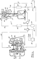
- Figure 1 is a schematic view of an integrated hydraulic system connected to electrohydraulically controlled valve assembly and hydraulic assisted turbocharger in accordance with the present invention.
- Figure 1 shows an integrated hydraulic system connected to an electrohydraulic
engine valve assembly 8 and a hydraulically assistedturbocharger 80. While this figure shows one possible embodiment for the valve train and turbocharger, other hydraulic valve trains and turbochargers can also have similarly integrated hydraulic systems to provide improvements in cost, weight and parasitic losses. An electrohydraulic valve train is shown in detail in U.S. Patent 5,255,641 to Schechter, which is incorporated herein by reference. - A single
engine valve assembly 8 of an electrohydraulically controlled valve train is shown in Fig. 1. Anengine valve 10, for inlet air or exhaust as the case may be, is located within acylinder head 12. Avalve piston 26, fixed to the top of theengine valve 10, is slidable within the limits ofpiston chamber 30. - Fluid is selectively supplied to the
volume 25 above thepiston 26 from a high pressure oil reservoir 40 and a lowpressure oil reservoir 42 hydraulically connected through ahigh pressure line 44 and alow pressure line 46, respectively, to a high pressure port 48 and alow pressure port 50, respectively. - The
volume 25 is connected to the high pressure oil reservoir 40 through asolenoid valve 64 or acheck valve 66, or to the lowpressure oil reservoir 42 throughsolenoid valve 68 or acheck valve 70. Thevolume 27 below thepiston 26 is always connected to the high pressure oil reservoir 40.Fluid return line 72 provides a means for returning to a sump or lowpressure oil supply 54 any fluid which leaks out of thepiston chamber 30. - The engine valve opening is controlled by the high-
pressure solenoid valve 64 which opens, causing valve acceleration, and closes, causing deceleration. Opening and closing of the lowpressure solenoid valve 68 controls the engine valve closing. - During engine valve opening, the high
pressure solenoid valve 64 opens and the net pressure force acting on thepiston 26 accelerates theengine valve 10 downward. When the highpressure solenoid valve 64 closes, pressure above thepiston 26 drops, and the piston decelerates pushing the fluid from thevolume 27 below it back into the high pressure oil reservoir 40. Low pressure fluid flowing through the lowpressure check valve 70 prevents void formation in the volume above thepiston 26 during deceleration. When the downward motion of theengine valve 10 stops, the lowpressure check valve 70 closes and theengine valve 10 remains locked in its open position. - The process of valve closing is similar, in principle, to that of valve opening. The low
pressure solenoid valve 68 opens, the pressure above thepiston 26 drops and the net pressure force acting on thepiston 26 accelerates theengine valve 10 upward. When the lowpressure solenoid valve 68 closes, pressure above thepiston 26 rises, and thepiston 26 decelerates pushing the fluid from thevolume 25 above it through the high-pressure check valve 66 back into the high-pressure oil reservoir 40. - Figure 1 also shows a hydraulically assisted
turbocharger 80 connected to the integrated hydraulic system 32. The turbocharger includes aturbocharger shaft 82, mounted in ahousing 83, having acompressor wheel 84 coupled to one end and a turbine wheel 86 coupled to the other. Coupled to a centre portion of theshaft 82 is an impulse type turbine 88, such as a Pelton Wheel. Anozzle jet 90 is located in close proximity to the impulse turbine 88 and connected to a high pressure source of fluid via ahigh pressure line 92. On the other side of the turbine 88 is anoutlet 94 leading to thesump 54. Energy is transferred to the turbocharger shaft via thenozzle 90 jetting high pressure oil against blades of the turbine 88. This helps to overcome the inertia of theturbocharger 80, and supplements exhaust energy input to the turbocharger at low engine operating speeds and during increasing load conditions at any speed. - The high pressure oil needed for both of the above described systems is supplied by the integrated hydraulic system 32. Figure 1 shows a variable displacement
hydraulic pump 52 connected to the reservoir orsump 54 bylow pressure line 34. Thehydraulic pump 52 is equipped with a pump controller or apressure regulating device 58. Thepressure regulator 58 maintains the required pressure in the high pressure system, regardless of changes in oil consumption, by varying the oil delivery. Fluid in the lowpressure oil reservoir 42 of thevalve assembly 8 is maintained at a fixed low pressure by means of discharge valve orcheck valve 60, connected to thesump 54 vialow pressure line 34. - The
pump 52 continuously supplies oil to the high pressure oil reservoir 40 of thehydraulic valve train 8. Since the fluid in the high pressure oil reservoir 40 in thevalve assembly 8 is subject only to expansion and contraction, the pumping work of thepump 52 is largely limited to that necessary to compensate for internal leakage through clearances.Pump 52 is also connected tohigh pressure line 92, to supply high pressure oil to the hydraulic turbine wheel 88 in theturbocharger 80. Alonghigh pressure line 92, between thepump 52 andnozzle jet 90, is asolenoid valve 36. - The
solenoid valve 36 is normally closed but opens whenever it receives an electronic activation signal from anengine control system 38. Thecontrol system 38 continuously monitors the operation of the engine. Whenever there is instantaneous demand for high engine torque, but the torque supplied by turbine 86 withinturbocharger 80 will be too low for quick power boost,engine control system 38 sends a signal andsolenoid 36 is opened, causing a flow of high pressure oil to be supplied to turbine 86, which quickly accelerates theturbocharger 80, thus providing a power boost to the engine. As soon as the engine speed and power reaches the level at which the turbine develops adequate torque, thesolenoid valve 36 is closed and the supply of hydraulic power to theturbocharger 80 is terminated. Hydraulic system 32 also preferably includes ahydraulic accumulator 39, which helps to reduce any transient pressure fluctuations that may occur during activation and deactivation of thesolenoid valve 36.
Claims (7)
- An internal combustion engine comprising:
a plurality of engine valves (10);
hydraulic valve means (64, 66, 68, 70) for operating the engine valves (10);
a hydraulically assisted turbocharger (80); and
a common source (32) of hydraulic power for operating the hydraulic valve means (64,66, 68, 70) and the hydraulically assisted turbocharger (80). - An engine according to claim 1 further comprising a control means for operating the hydraulic valve means and the hydraulic turbo-assist means.
- An integrated hydraulic system for controlling electrohydraulically actuated engine valves and a hydraulically assisted turbocharger, the hydraulic system comprising:
a hydraulic pump connected to a fluid reservoir for pressurising hydraulic fluid;
a high pressure line connected to the hydraulically controlled valve train and the hydraulically assisted turbocharger from the hydraulic pump;
a pressure regulating device coupled to the hydraulic pump for maintaining pressure in the high pressure line; and
valve means for selectively restricting flow in the high pressure line between the hydraulic pump and the hydraulically assisted turbocharger. - An integrated hydraulic system according to claim 3, wherein the hydraulic control system further comprises a hydraulic accumulator connected to the high pressure line.
- An integrated hydraulic system according to claim 3, wherein the hydraulic control system further comprises a high pressure reservoir connected along the high pressure line between the hydraulic pump and the hydraulically controlled valve train.
- An integrated hydraulic system according to claim 3, wherein the valve means comprises a solenoid valve connected along the high pressure line and an engine control system electrically connected to the solenoid valve for controlling the opening and closing of the solenoid valve.
- An integrated hydraulic system according to claim 3, wherein the hydraulically controlled valve train includes a fluid return to the fluid reservoir and the hydraulically assisted turbocharger includes a fluid return to the fluid reservoir.
Applications Claiming Priority (2)
| Application Number | Priority Date | Filing Date | Title |
|---|---|---|---|
| US08/167,302 US5375419A (en) | 1993-12-16 | 1993-12-16 | Integrated hydraulic system for electrohydraulic valvetrain and hydraulically assisted turbocharger |
| US167302 | 1993-12-16 |
Publications (2)
| Publication Number | Publication Date |
|---|---|
| EP0659983A1 true EP0659983A1 (en) | 1995-06-28 |
| EP0659983B1 EP0659983B1 (en) | 1998-07-15 |
Family
ID=22606800
Family Applications (1)
| Application Number | Title | Priority Date | Filing Date |
|---|---|---|---|
| EP94308562A Expired - Lifetime EP0659983B1 (en) | 1993-12-16 | 1994-11-21 | Hydraulic system for engines |
Country Status (3)
| Country | Link |
|---|---|
| US (1) | US5375419A (en) |
| EP (1) | EP0659983B1 (en) |
| DE (1) | DE69411693T2 (en) |
Cited By (1)
| Publication number | Priority date | Publication date | Assignee | Title |
|---|---|---|---|---|
| US11035289B2 (en) | 2016-11-30 | 2021-06-15 | Vn-Ac Ip Ltd | Kinetic energy recovery boosting system for turbocharger utilising hydraulic braking |
Families Citing this family (31)
| Publication number | Priority date | Publication date | Assignee | Title |
|---|---|---|---|---|
| US5474041A (en) * | 1994-12-28 | 1995-12-12 | Cummins Engine Company, Inc. | Engine lubrication system with decreased power draw |
| US5456223A (en) * | 1995-01-06 | 1995-10-10 | Ford Motor Company | Electric actuator for spool valve control of electrohydraulic valvetrain |
| US5497736A (en) * | 1995-01-06 | 1996-03-12 | Ford Motor Company | Electric actuator for rotary valve control of electrohydraulic valvetrain |
| US5456221A (en) * | 1995-01-06 | 1995-10-10 | Ford Motor Company | Rotary hydraulic valve control of an electrohydraulic camless valvetrain |
| US5456222A (en) * | 1995-01-06 | 1995-10-10 | Ford Motor Company | Spool valve control of an electrohydraulic camless valvetrain |
| US5619965A (en) * | 1995-03-24 | 1997-04-15 | Diesel Engine Retarders, Inc. | Camless engines with compression release braking |
| US5572961A (en) * | 1995-04-05 | 1996-11-12 | Ford Motor Company | Balancing valve motion in an electrohydraulic camless valvetrain |
| US5562070A (en) * | 1995-07-05 | 1996-10-08 | Ford Motor Company | Electrohydraulic camless valvetrain with rotary hydraulic actuator |
| US6067946A (en) * | 1996-12-16 | 2000-05-30 | Cummins Engine Company, Inc. | Dual-pressure hydraulic valve-actuation system |
| US6041602A (en) * | 1997-06-09 | 2000-03-28 | Southwest Research Institute | Hydraulically-actuated exhaust gas recirculation system and turbocharger for engines |
| US6412278B1 (en) | 2000-11-10 | 2002-07-02 | Borgwarner, Inc. | Hydraulically powered exhaust gas recirculation system |
| US6739293B2 (en) * | 2000-12-04 | 2004-05-25 | Sturman Industries, Inc. | Hydraulic valve actuation systems and methods |
| DE10143330A1 (en) * | 2001-09-05 | 2003-03-20 | Bosch Gmbh Robert | Internal combustion engine with electrohydraulic valve controler, has hydraulic load supplied with excess fluid from pump for producing volumetric fluid flow for valve controler |
| DE10155669A1 (en) * | 2001-11-13 | 2003-05-22 | Bosch Gmbh Robert | Device for controlling at least one gas exchange valve |
| CN1287069C (en) * | 2003-11-27 | 2006-11-29 | 宁波华液机器制造有限公司 | Pressure differential style air valve variation control system |
| US7174714B2 (en) * | 2004-12-13 | 2007-02-13 | Caterpillar Inc | Electric turbocompound control system |
| US20080121218A1 (en) * | 2004-12-13 | 2008-05-29 | Caterpillar Inc. | Electric turbocompound control system |
| US20060196179A1 (en) * | 2005-03-01 | 2006-09-07 | Arun Kesavan | Load-sensing integrated brake and fan hydraulic system |
| US7866286B2 (en) * | 2006-09-13 | 2011-01-11 | Gm Global Technology Operations, Inc. | Method for valve seating control for an electro-hydraulic engine valve |
| DE102009029735A1 (en) | 2009-06-22 | 2010-12-23 | Volkswagen Ag | Exhaust gas supercharger, e.g. for a vehicle diesel motor, has a cogwheel link from the shaft to a hydraulic turbine as an additional drive to support its running |
| WO2011071529A1 (en) | 2009-12-08 | 2011-06-16 | Hydracharge Llc | Hydraulic turbo accelerator apparatus |
| US10082070B2 (en) | 2010-12-08 | 2018-09-25 | Hydracharge Llc | High performance turbo-hydraulic compressor |
| US20120180481A1 (en) * | 2011-01-19 | 2012-07-19 | Davorin Kapich | Hybrid turbocharger system with brake energy revovery |
| US20120180480A1 (en) * | 2011-01-19 | 2012-07-19 | Davorin Kapich | Hybrid turbocharger system with brake energy revovery |
| US11591952B2 (en) | 2012-05-21 | 2023-02-28 | Hydracharge Llc | High performance turbo-hydraulic compressor |
| US9127624B2 (en) * | 2012-06-20 | 2015-09-08 | General Electric Company | Systems and methods for a hydraulically actuated engine valve |
| US9181043B1 (en) | 2014-06-03 | 2015-11-10 | The Procter & Gamble Company | Elevation change system for a rotary device |
| US9302856B2 (en) | 2014-06-03 | 2016-04-05 | The Procter & Gamble Company | Method for adjusting a rotary device |
| US9371195B2 (en) | 2014-06-03 | 2016-06-21 | The Procter & Gamble Company | Adjustment system for a rotary device |
| US10315860B2 (en) | 2016-05-25 | 2019-06-11 | The Procter And Gamble Company | Article handling device |
| US11319870B1 (en) | 2021-04-13 | 2022-05-03 | Eyal Ezra | Turbocharger control valve for retaining back pressure and maintaining boost pressure |
Citations (5)
| Publication number | Priority date | Publication date | Assignee | Title |
|---|---|---|---|---|
| US4188925A (en) * | 1977-06-09 | 1980-02-19 | Jordan Edgar R | Engine cylinder valve control mechanism and cylinder head and engine incorporating same |
| EP0022678A1 (en) * | 1979-07-16 | 1981-01-21 | The Garrett Corporation | Internal combustion engine turbochargers having auxiliary driving arrangements, and engines incorporating such turbochargers |
| EP0397521A1 (en) * | 1989-05-11 | 1990-11-14 | Isuzu Ceramics Research Institute Co., Ltd. | Engine cycle control system |
| US5113658A (en) * | 1990-05-21 | 1992-05-19 | Allied-Signal, Inc. | Hydraulic assist turbocharger system |
| EP0520633A2 (en) * | 1991-06-24 | 1992-12-30 | Ford Motor Company Limited | Hydraulically operated valve control system for an internal combustion engine |
Family Cites Families (3)
| Publication number | Priority date | Publication date | Assignee | Title |
|---|---|---|---|---|
| US2968914A (en) * | 1955-07-06 | 1961-01-24 | Laval Steam Turbine Co | Turbocharging of internal combustion engines |
| US4322949A (en) * | 1979-07-16 | 1982-04-06 | The Garrett Corporation | Hydraulic assist turbocharger system |
| US5255641A (en) * | 1991-06-24 | 1993-10-26 | Ford Motor Company | Variable engine valve control system |
-
1993
- 1993-12-16 US US08/167,302 patent/US5375419A/en not_active Expired - Fee Related
-
1994
- 1994-11-21 EP EP94308562A patent/EP0659983B1/en not_active Expired - Lifetime
- 1994-11-21 DE DE69411693T patent/DE69411693T2/en not_active Expired - Fee Related
Patent Citations (5)
| Publication number | Priority date | Publication date | Assignee | Title |
|---|---|---|---|---|
| US4188925A (en) * | 1977-06-09 | 1980-02-19 | Jordan Edgar R | Engine cylinder valve control mechanism and cylinder head and engine incorporating same |
| EP0022678A1 (en) * | 1979-07-16 | 1981-01-21 | The Garrett Corporation | Internal combustion engine turbochargers having auxiliary driving arrangements, and engines incorporating such turbochargers |
| EP0397521A1 (en) * | 1989-05-11 | 1990-11-14 | Isuzu Ceramics Research Institute Co., Ltd. | Engine cycle control system |
| US5113658A (en) * | 1990-05-21 | 1992-05-19 | Allied-Signal, Inc. | Hydraulic assist turbocharger system |
| EP0520633A2 (en) * | 1991-06-24 | 1992-12-30 | Ford Motor Company Limited | Hydraulically operated valve control system for an internal combustion engine |
Cited By (1)
| Publication number | Priority date | Publication date | Assignee | Title |
|---|---|---|---|---|
| US11035289B2 (en) | 2016-11-30 | 2021-06-15 | Vn-Ac Ip Ltd | Kinetic energy recovery boosting system for turbocharger utilising hydraulic braking |
Also Published As
| Publication number | Publication date |
|---|---|
| DE69411693D1 (en) | 1998-08-20 |
| EP0659983B1 (en) | 1998-07-15 |
| DE69411693T2 (en) | 1998-11-12 |
| US5375419A (en) | 1994-12-27 |
Similar Documents
| Publication | Publication Date | Title |
|---|---|---|
| EP0659983B1 (en) | Hydraulic system for engines | |
| US5456222A (en) | Spool valve control of an electrohydraulic camless valvetrain | |
| US5410994A (en) | Fast start hydraulic system for electrohydraulic valvetrain | |
| CN101379296B (en) | Variable displacement variable pressure vane pump system | |
| US5062498A (en) | Hydrostatic power transfer system with isolating accumulator | |
| US5373817A (en) | Valve deactivation and adjustment system for electrohydraulic camless valvetrain | |
| US10082070B2 (en) | High performance turbo-hydraulic compressor | |
| US20120180481A1 (en) | Hybrid turbocharger system with brake energy revovery | |
| US5113658A (en) | Hydraulic assist turbocharger system | |
| US5878724A (en) | Diesel vehicle primary fuel pump driven by return fuel energy | |
| US20120180480A1 (en) | Hybrid turbocharger system with brake energy revovery | |
| GB2304152A (en) | Decompression diesel engine braking with exhaust valve actuated by fuel injection pressure | |
| JPS63179141A (en) | Hydraulic control device for engine | |
| JPS6027812B2 (en) | Control device for turbo charger mechanism | |
| CN104822911A (en) | Gas exchange valve arrangement | |
| KR940015189A (en) | Compression control apparatus for exhaust gas turbochargers | |
| WO1998051910A1 (en) | Control system for hydraulic supercharger system | |
| US6314734B1 (en) | Internal combustion engine with AT regulator | |
| JPS6231522A (en) | Decelerating energy recoverer for vehicle | |
| US11591952B2 (en) | High performance turbo-hydraulic compressor | |
| US6446598B1 (en) | Compression brake actuation system and method | |
| JPS60169614A (en) | Open/close timing controller for exhaust valve | |
| US6318084B1 (en) | Internal-combustion engine having an engine braking device | |
| EP1217179B1 (en) | Compression brake actuation system and method | |
| RU2158696C1 (en) | Pump-accumulator hydraulic drive |
Legal Events
| Date | Code | Title | Description |
|---|---|---|---|
| PUAI | Public reference made under article 153(3) epc to a published international application that has entered the european phase |
Free format text: ORIGINAL CODE: 0009012 |
|
| AK | Designated contracting states |
Kind code of ref document: A1 Designated state(s): DE FR GB |
|
| 17P | Request for examination filed |
Effective date: 19951106 |
|
| 17Q | First examination report despatched |
Effective date: 19970314 |
|
| GRAG | Despatch of communication of intention to grant |
Free format text: ORIGINAL CODE: EPIDOS AGRA |
|
| GRAG | Despatch of communication of intention to grant |
Free format text: ORIGINAL CODE: EPIDOS AGRA |
|
| GRAH | Despatch of communication of intention to grant a patent |
Free format text: ORIGINAL CODE: EPIDOS IGRA |
|
| GRAH | Despatch of communication of intention to grant a patent |
Free format text: ORIGINAL CODE: EPIDOS IGRA |
|
| GRAA | (expected) grant |
Free format text: ORIGINAL CODE: 0009210 |
|
| AK | Designated contracting states |
Kind code of ref document: B1 Designated state(s): DE FR GB |
|
| REF | Corresponds to: |
Ref document number: 69411693 Country of ref document: DE Date of ref document: 19980820 |
|
| ET | Fr: translation filed | ||
| PLBE | No opposition filed within time limit |
Free format text: ORIGINAL CODE: 0009261 |
|
| STAA | Information on the status of an ep patent application or granted ep patent |
Free format text: STATUS: NO OPPOSITION FILED WITHIN TIME LIMIT |
|
| 26N | No opposition filed | ||
| REG | Reference to a national code |
Ref country code: FR Ref legal event code: TP Ref country code: FR Ref legal event code: CD |
|
| PGFP | Annual fee paid to national office [announced via postgrant information from national office to epo] |
Ref country code: FR Payment date: 20001121 Year of fee payment: 7 |
|
| REG | Reference to a national code |
Ref country code: GB Ref legal event code: IF02 |
|
| PG25 | Lapsed in a contracting state [announced via postgrant information from national office to epo] |
Ref country code: FR Free format text: LAPSE BECAUSE OF NON-PAYMENT OF DUE FEES Effective date: 20020730 |
|
| REG | Reference to a national code |
Ref country code: FR Ref legal event code: ST |
|
| REG | Reference to a national code |
Ref country code: FR Ref legal event code: ST |
|
| PGFP | Annual fee paid to national office [announced via postgrant information from national office to epo] |
Ref country code: GB Payment date: 20031027 Year of fee payment: 10 |
|
| PGFP | Annual fee paid to national office [announced via postgrant information from national office to epo] |
Ref country code: DE Payment date: 20031128 Year of fee payment: 10 |
|
| PG25 | Lapsed in a contracting state [announced via postgrant information from national office to epo] |
Ref country code: GB Free format text: LAPSE BECAUSE OF NON-PAYMENT OF DUE FEES Effective date: 20041121 |
|
| PG25 | Lapsed in a contracting state [announced via postgrant information from national office to epo] |
Ref country code: DE Free format text: LAPSE BECAUSE OF NON-PAYMENT OF DUE FEES Effective date: 20050601 |
|
| GBPC | Gb: european patent ceased through non-payment of renewal fee |
Effective date: 20041121 |