EP0659665A1 - Device for continuously feeding articles from a main conveying line to intermediate outlet ways arranged angularly with respect to the main line - Google Patents
Device for continuously feeding articles from a main conveying line to intermediate outlet ways arranged angularly with respect to the main line Download PDFInfo
- Publication number
- EP0659665A1 EP0659665A1 EP94830585A EP94830585A EP0659665A1 EP 0659665 A1 EP0659665 A1 EP 0659665A1 EP 94830585 A EP94830585 A EP 94830585A EP 94830585 A EP94830585 A EP 94830585A EP 0659665 A1 EP0659665 A1 EP 0659665A1
- Authority
- EP
- European Patent Office
- Prior art keywords
- articles
- conveying line
- main
- line
- raising means
- Prior art date
- Legal status (The legal status is an assumption and is not a legal conclusion. Google has not performed a legal analysis and makes no representation as to the accuracy of the status listed.)
- Withdrawn
Links
- 238000011144 upstream manufacturing Methods 0.000 claims abstract description 3
- 230000008878 coupling Effects 0.000 description 1
- 238000010168 coupling process Methods 0.000 description 1
- 238000005859 coupling reaction Methods 0.000 description 1
- 230000009849 deactivation Effects 0.000 description 1
- 238000004519 manufacturing process Methods 0.000 description 1
Images


Classifications
-
- B—PERFORMING OPERATIONS; TRANSPORTING
- B65—CONVEYING; PACKING; STORING; HANDLING THIN OR FILAMENTARY MATERIAL
- B65G—TRANSPORT OR STORAGE DEVICES, e.g. CONVEYORS FOR LOADING OR TIPPING, SHOP CONVEYOR SYSTEMS OR PNEUMATIC TUBE CONVEYORS
- B65G47/00—Article or material-handling devices associated with conveyors; Methods employing such devices
- B65G47/74—Feeding, transfer, or discharging devices of particular kinds or types
- B65G47/82—Rotary or reciprocating members for direct action on articles or materials, e.g. pushers, rakes, shovels
Definitions
- the present invention relates to transferring various articles to outlet ways provided along a main conveying line.
- Such auxiliary conveying lines are usually arranged at a certain angle with respect to the main line, in particular perpendicular thereto.
- the object of the present invention is to propose a device that allows for a continuous selective transferring of articles to one or more intermediate outlets placed along a main conveying line of these articles.
- the reference numeral 1 indicates the main line conveying the articles 2.
- the conveying line 1 includes a slide surface 3 for the articles 2, that is formed, in correspondence with the operative zone of the subject device, by a plurality of longitudinal plates 4 arranged side by side.
- the cross bars 5 are aimed at pushing on the back side of articles 2, or of groups of articles transversely flanked with each other, to be conveyed.
- the upper active run 8a of the conveying line 8 is located over the slide surface 3 of the main line 1, at a suitable distance therefrom, so as to allow the articles conveyed on the line 1 to pass under it.
- the device for taking over the articles 2 has, upstream of the outlet way 7, a plurality of raising means 9 moved by a rotary drum means 10.
- the drum means 10 is situated under the slide surface 3 of the main conveying line 1 and rotates around a horizontal axis transversal to the line 1.
- the raising means 9, e.g. three as in the illustrated case, are arranged regularly along the periphery of the rotary drum 10, and have the form of a comb, constituted by a plurality of prongs 11, carried side by side by a bar 12.
- the bar 12 is rotatably mounted between a pair of circular heads 13 of the rotary drum 10.
- the circular heads 13 are joined to a driving shaft 14 of the rotary drum 10, rotatably supported by a pair of side walls 15 of the device ( Figure 6).
- the driving shaft 14 of the rotary drum 10 can be driven to rotate either by driving means 16, through a flexible link 17, or, preferably, by not illustrated means, interlocked with the main driving of the machine in which the present device is inserted.
- a front coupling clutch 18 is mounted on the driving shaft 14 to allow deactivation of the taking over device.
- the driving shaft 14 is also equipped with braking means 19 for stopping the device.
- each bar 12 of the raising means 9, protruding from the circular head 13 of the rotary drum 10, has e toothed wheel 20 fastened thereto.
- the toothed wheels 20 are rotated by a toothed belt 21 that are trained around a pair of idler pulleys 22, carried by the said head 13, and a pinion 23, fixed to the adjacent side wall 15.
- the pinion 23 and the driving shaft 14 are coaxial.
- the pinion 23 and the toothed wheels 20 are equal in diameter.
- the idler pulleys 22 are situated symmetrically at both side of the pinion 23.
- the raising means 9, carried by the rotary drum 10, move while keeping the loading surface delimited by the prongs 11 with constant horizontal attitude.
- Pushing means 24, made to move by a chain 25 located over the main conveying line 1, are aimed at cooperating with the raising means 9.
- the chain 25 is trained around a pair of sprockets 26.
- the speed with which the said chain 25 is operated is suitably bigger than the advancement speed of the articles 2 along the main line 1.
- the pushers 24 are hinged to the chain 25 about respective pivot 27, and bear rollers 28, aimed at running along a longitudinal guide 29 in correspondence with the active run of the same chain 25.
- the terminal part 30 of the guide 29 is suitably inclined and makes the pushers 24 to rotate, in a direction contrary to the pusher motion, when the articles 2 are released.
- the flat 31 is formed by a plurality of longitudinal plates 32, arranged side by side, correspondent to the plates 4 that form the slide surface 3 of the main line 1.
- Each of the comb-shaped raising means 9 is brought in turn, by the rotation of the drum 10, to cross the slide surface 3 of the main line 1 so as to raise a respective article 2 from this surface 3.
- prongs 11 of the raising means 9 are staggered with respect to the plates 4 of the slide surface 3, so that, in the raising phase, they insert between these plates 4, as it is seen in Figure 5.
- the raising means goes first up and then down, as a result of the trajectory imposed to the bar 12 by the rotary drum 10.
- the article 2, raised by the raising means 9, is pushed by a relative pusher 24, guided along the guide 29 and operated with the speed suitably bigger than the advancement speed of the main line 1.
- the rotary drum 10 is disconnected and stopped, so as to avoid the raising of the articles 2.
- Suitable sensors define the position in which the rotary drum 10 is stopped so that the raising means 9 do not interfere with the slide surface 3 of the main line 1.
- the clutch 18 allows to keep the proper phase relation for rotation of the drum 10, movements of the conveying line 1 and movements of the pushers 24.
- the described device for taking over the articles allows for selective taking over thereof from the main line and for transferring them to a suitable outlet way.
- the articles are selectively taken over in a continuous way, without stopping or slowing down or moving the articles away from the conveying path.
Landscapes
- Engineering & Computer Science (AREA)
- Mechanical Engineering (AREA)
- Specific Conveyance Elements (AREA)
- Special Conveying (AREA)
- Sorting Of Articles (AREA)
- Image Analysis (AREA)
Abstract
Description
- The present invention relates to transferring various articles to outlet ways provided along a main conveying line.
- It is known that in many manufacturing fields the articles, after having undergone other operative phases along the main conveying line, must be transferred to auxiliary conveying lines, in correspondence with intermediate outlets.
- Such auxiliary conveying lines are usually arranged at a certain angle with respect to the main line, in particular perpendicular thereto.
- Often, a selective transferring to different outlets is required so as to separate different articles coming from the same main line.
- This requirement has not been met yet in a simple and efficient way, since the transferring of the articles to different outlets usually necessitates complicated devices, that obviously reduces the productivity.
- The object of the present invention is to propose a device that allows for a continuous selective transferring of articles to one or more intermediate outlets placed along a main conveying line of these articles.
- The above mentioned object is achieved in accordance to the contents of the claims.
- The characteristic features of the present invention are pointed out in the following, with the particular reference to the enclosed drawings, in which:
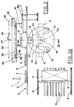
- Figure 1 shows a schematic side view of the device being the subject of the invention;
- Figure 2 shows the same schematic side view of the device in a different operative step;
- Figure 2a shows a plan view of a part of the main line conveying the articles which advance according to the arrow A of Figure 2;
- Figures 3 and 4 show side views of subsequent operative steps performed by the device;
- Figure 5 shows a side view of a further operative step of the device;
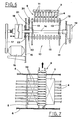
- Figure 6 shows a sectional view taken along the line V-V of Figure 2;
- Figure 7 shows a sectional view taken along the line VII-VII of Figure 5.
- With reference to the above mentioned figures, the reference numeral 1 indicates the main line conveying the
articles 2. - The conveying line 1 includes a
slide surface 3 for thearticles 2, that is formed, in correspondence with the operative zone of the subject device, by a plurality oflongitudinal plates 4 arranged side by side. - Over the
slide surface 3 there are a plurality of equispacedmovable cross bars 5 that are carried, at their ends, by chain means 6, operated in direction longitudinal to the line 1. - The
cross bars 5 are aimed at pushing on the back side ofarticles 2, or of groups of articles transversely flanked with each other, to be conveyed. - Along the main conveying line, there is located at least one
intermediate way 7, to which thearticles 2 are discharged, including arelative conveying line 8 perpendicular to the same main line. - Preferably, there are a plurality of intermediate outlet ways, properly spaced apart, for selectively taking over the
articles 2 from the main conveying line 1. - It is to be noticed that the upper
active run 8a of the conveyingline 8 is located over theslide surface 3 of the main line 1, at a suitable distance therefrom, so as to allow the articles conveyed on the line 1 to pass under it. - The device for taking over the
articles 2 has, upstream of theoutlet way 7, a plurality of raisingmeans 9 moved by a rotary drum means 10. - The drum means 10 is situated under the
slide surface 3 of the main conveying line 1 and rotates around a horizontal axis transversal to the line 1. - The
raising means 9, e.g. three as in the illustrated case, are arranged regularly along the periphery of therotary drum 10, and have the form of a comb, constituted by a plurality ofprongs 11, carried side by side by abar 12. - The
bar 12 is rotatably mounted between a pair ofcircular heads 13 of therotary drum 10. - The
circular heads 13 are joined to adriving shaft 14 of therotary drum 10, rotatably supported by a pair ofside walls 15 of the device (Figure 6). - The
driving shaft 14 of therotary drum 10 can be driven to rotate either bydriving means 16, through aflexible link 17, or, preferably, by not illustrated means, interlocked with the main driving of the machine in which the present device is inserted. - A
front coupling clutch 18 is mounted on thedriving shaft 14 to allow deactivation of the taking over device. - The driving
shaft 14 is also equipped with braking means 19 for stopping the device. - One end of each
bar 12 of the raising means 9, protruding from thecircular head 13 of therotary drum 10, has etoothed wheel 20 fastened thereto. - The
toothed wheels 20 are rotated by atoothed belt 21 that are trained around a pair ofidler pulleys 22, carried by the saidhead 13, and apinion 23, fixed to theadjacent side wall 15. Thepinion 23 and thedriving shaft 14 are coaxial. Thepinion 23 and thetoothed wheels 20 are equal in diameter. - The
idler pulleys 22 are situated symmetrically at both side of thepinion 23. - It is to be noticed that, during the rotation of the
drum 10, a counter-rotation of thebars 12 of theraising means 9 is caused by the gear realised by thetoothed wheels belt 21. - In particular, the counter-rotation of the
bars 12 is such that the position of raisingmeans 9 is maintained unchanged. - Therefore, the
raising means 9, carried by therotary drum 10, move while keeping the loading surface delimited by theprongs 11 with constant horizontal attitude. - Pushing means 24, made to move by a
chain 25 located over the main conveying line 1, are aimed at cooperating with theraising means 9. - The
chain 25 is trained around a pair ofsprockets 26. The speed with which the saidchain 25 is operated is suitably bigger than the advancement speed of thearticles 2 along the main line 1. - The
pushers 24 are hinged to thechain 25 aboutrespective pivot 27, andbear rollers 28, aimed at running along alongitudinal guide 29 in correspondence with the active run of thesame chain 25. - The
terminal part 30 of theguide 29 is suitably inclined and makes thepushers 24 to rotate, in a direction contrary to the pusher motion, when thearticles 2 are released. - The transferring of the
articles 2 on theconveying line 8 of theoutlet way 7 is facilitated by anintermediate flat 31, slightly inclined in its initial part, situated at the level of theupper run 8a of thisconveying line 8. - The
flat 31 is formed by a plurality oflongitudinal plates 32, arranged side by side, correspondent to theplates 4 that form theslide surface 3 of the main line 1. - Operation of the present device is described in the following, beginning from the step in which an
article 2 is taken over by one of theraising means 9 that is moved, in the direction indicated by the arrow B, by the rotary drum 10 (see Figure 1). - Each of the comb-
shaped raising means 9 is brought in turn, by the rotation of thedrum 10, to cross theslide surface 3 of the main line 1 so as to raise arespective article 2 from thissurface 3. (Figure 2) - It is to be noticed that the
prongs 11 of the raisingmeans 9 are staggered with respect to theplates 4 of theslide surface 3, so that, in the raising phase, they insert between theseplates 4, as it is seen in Figure 5. - It is also to be noticed that, at the moment of taking over the
article 2 from the main line 1, the speed of theraising means 9 is substantially equal to the advancement speed of the same line 1. - In operation, the raising means goes first up and then down, as a result of the trajectory imposed to the
bar 12 by therotary drum 10. - In the highest position of the raising means 9, its upper surface is substantially lined up with the
intermediate flat 31 and with theupper run 8a of theconveying line 8 of theoutlet 7. - The
article 2, raised by theraising means 9, is pushed by arelative pusher 24, guided along theguide 29 and operated with the speed suitably bigger than the advancement speed of the main line 1. - Consequently, the
pusher 24 transfers the above mentionedarticle 2 from theraising means 9 to the intermediate flat 31 (Figure 3). - While the
raising means 9 goes down, thepusher 24 transfers thearticle 2 from theintermediate flat 31 to theconveying line 8 of the outlet way 7 (Figure 4). - When the
article 2 has been transferred to theoutlet 7, theroller 28 of thepusher 24 enters theinclined terminal part 30 of theguide 29, so that thesame pusher 24 is rotated accordingly and subsequently, the transferredarticle 2 is not more acted on by thesame pusher 24. - Thus it is possible to transfer the
articles 2 from the main line 1 to theoutlet way 7 in a continuous way. - When the
article 2, or group of articles, is not to be transferred to the intermediate outlet way, therotary drum 10 is disconnected and stopped, so as to avoid the raising of thearticles 2. - Consequently, the articles proceed along the main line 1 passing under the
upper run 8a of the conveying line 8 (Figure 5). - Suitable sensors define the position in which the
rotary drum 10 is stopped so that theraising means 9 do not interfere with theslide surface 3 of the main line 1. - It is to be noticed that, when the articles are to be taken over again, the
clutch 18 allows to keep the proper phase relation for rotation of thedrum 10, movements of the conveying line 1 and movements of thepushers 24. - The described device for taking over the articles allows for selective taking over thereof from the main line and for transferring them to a suitable outlet way.
- Therefore, it is possible to select groups of different articles to be moved to respective outlets in a more suitable way, according to predetermined programs or to different productive requests of the equipment.
- As it has already been pointed out, the articles are selectively taken over in a continuous way, without stopping or slowing down or moving the articles away from the conveying path.
- This increases the equipment productivity and avoids the risk of wrong functioning or the like.
- It is understood that what above has been described as a mere, not limitative example, therefore all possible constructive variants are protected by the present technical solution, as described above and claimed in the following.
Claims (9)
- Device for continuously feeding articles from a main conveying line to intermediate outlet ways which are arranged angularly with respect to the said main line, the device being characterised in that it includes:
at least a raising means (9) located beneath the slide surface (3) of the main conveying line, upstream of an intermediate outlet way (7), this raising means being operated in suitable phase relation with proceeding of the articles (2) along the said main line (1), in such a way to take over and raise articles (2) from the said slide surface (3);
a pushing means (24) movable longitudinally over the said main conveying line (1), so as to transfer the raised articles (2) from the raising means (9) to the intermediate outlet way (7). - Device according to claim 1, characterised in that it further includes rotary drum means (10), situated beneath the slide surface (3) and driven to rotate around a horizontal axis transverse to the said main line (1) this rotary drum means (10) carrying along its periphery a series of the said raising means (9) operated in turn to take over respective articles (2) and to raise said articles up to an intermediate transferring flat (31) adjacent to the said outlet way (7), with pushing means (24) situated close to the same intermediate flat (31) for transferring the said articles to the said outlet way (7).
- Device according to claim 2, characterised in that each one of the said raising means (9) is shaped like a comb and includes a plurality of prongs (11) that insert among corresponding staggered longitudinal plates (4) forming the said slide surface (3), the said prongs being supported side by side by a bar (12) rotatably mounted between a pair of circular heads (13) of the said rotary drum means (10), the said heads being connected to a driving shaft (14) of the said rotary drum means (10).
- Device according to claim 2, characterised in that the said intermediate transferring flat (31) is formed by a plurality of longitudinal plates (32) arranged side by side at the level of the upper active run (8a) of a conveying line (8) of the said outlet way (7), so that the prongs (11) of the said raising means (9) can insert among the said plates (32).
- Device according to claim 2, characterised in that the said raising means (9) are driven to rotate in a direction contrary to the rotation direction of the said rotary drum means (10), so that the attitude of the said raising means (9) is maintained unchanged.
- Device according to claim 5, characterised in that the said raising means (9) are fixed to respective bars (12) rotatably supported by a pair of circular heads (13) of the said rotary drum (10), respective toothed wheels (20) being keyed to the ends of the said bars (12) and engaging a toothed belt (21) that is trained around idler pulleys (22) and a pinion (23) fixed to an adjacent side wall (15), the said pinion (23) and the said driving shaft (14) of the said rotary drum (10) being coaxial.
- Device according to claim 1, characterised in that the said outlet way (7) includes an outlet conveying line (8) arranged perpendicularly to the said main conveying line (1), the upper active run (8a) of the said outlet conveying line being located at a level higher than the said slide surface (3) of the said main conveying line (1), so that articles (2) being transported along the said main conveying line (1) may pass thereunder.
- Device according to claim 1, characterised in that it includes a plurality of the said pushing means (24) jointed to a chain (25) that is longitudinally arranged above the said main conveying line (1) and that is driven with a speed higher than the advancement speed of the said articles (2) along the said main conveying line (1).
- Device according to claim 8, characterised in that the said pushing means (24) are jointed to the said chain (25) at respective pivots (27) and are equipped with a roller (28) that is made to run along a longitudinal guide (29) adjacent to the active run of the said chain (25), the said guide (29) having a terminal part (30) that is inclined so as to make the said pushing means (24) to rotate in a direction contrary to the advancement direction of the articles (2), when the said articles are released.
Applications Claiming Priority (2)
| Application Number | Priority Date | Filing Date | Title |
|---|---|---|---|
| IT93BO000522A IT1264299B1 (en) | 1993-12-23 | 1993-12-23 | DEVICE FOR THE CONTINUOUS EXTRACTION OF ARTICLES FROM A MAIN LINE TO INTERMEDIATE EXITS PLACED AT AN ANGLE TO THIS |
| ITBO930522 | 1993-12-23 |
Publications (1)
| Publication Number | Publication Date |
|---|---|
| EP0659665A1 true EP0659665A1 (en) | 1995-06-28 |
Family
ID=11339377
Family Applications (1)
| Application Number | Title | Priority Date | Filing Date |
|---|---|---|---|
| EP94830585A Withdrawn EP0659665A1 (en) | 1993-12-23 | 1994-12-23 | Device for continuously feeding articles from a main conveying line to intermediate outlet ways arranged angularly with respect to the main line |
Country Status (3)
| Country | Link |
|---|---|
| US (1) | US5529167A (en) |
| EP (1) | EP0659665A1 (en) |
| IT (1) | IT1264299B1 (en) |
Cited By (7)
| Publication number | Priority date | Publication date | Assignee | Title |
|---|---|---|---|---|
| WO1998049083A3 (en) * | 1997-04-30 | 1999-02-11 | Siemens Ag | Device for transferring articles between two conveyors |
| EP1407991A1 (en) * | 2002-10-11 | 2004-04-14 | Ferag AG | Device for pushing of articles lying on a conveyor |
| EP2070847A1 (en) * | 2007-12-13 | 2009-06-17 | ETA SA Manufacture Horlogère Suisse | Diverter for conveyors |
| CN106743446A (en) * | 2017-01-19 | 2017-05-31 | 桐乡市佳顺自动化机械有限公司 | A kind of magnetic material arranges conveying equipment |
| CN106144570B (en) * | 2016-08-25 | 2018-08-03 | 莆田烟草物流有限公司 | A kind of semi-automatic sorting cigarette shifting device of anti-slip cigarette |
| WO2020094318A1 (en) * | 2018-11-08 | 2020-05-14 | Krones Ag | Device for grouping containers |
| CN118976722A (en) * | 2024-10-22 | 2024-11-19 | 常州三恒电器有限公司 | A kind of automatic testing and sorting machine for mutual inductor |
Families Citing this family (9)
| Publication number | Priority date | Publication date | Assignee | Title |
|---|---|---|---|---|
| US6349815B1 (en) * | 2000-02-14 | 2002-02-26 | Peters Machinery Corporation | In-line stacker machine for stacking cookies |
| NL1015030C2 (en) * | 2000-04-14 | 2001-10-16 | Fico Bv | Method and device for transporting electronic components. |
| JP2002120812A (en) * | 2000-10-16 | 2002-04-23 | Ishida Co Ltd | Product distributing mechanism in boxing system |
| ITBO20020049A1 (en) * | 2002-01-31 | 2003-07-31 | Casmatic Spa | VARIABLE PITCH APPARATUS, FOR PUSHING AND PHASE SUPPLY OF PRODUCTS TO A SUBSEQUENT WORK STATION |
| SE527834C2 (en) * | 2004-11-10 | 2006-06-13 | Norden Pac Dev Ab | Cardboard machine apparatus and method |
| DE102006045107B4 (en) * | 2006-09-21 | 2015-03-12 | Optima Nonwovens Gmbh | Reversing feed device for the cyclically linear feeding of stacked goods over a transport path |
| ES2376134T3 (en) * | 2008-06-13 | 2012-03-09 | Advanced Nuclear Fuels Gmbh | TRANSPORTATION AND INSULATION DEVICE. |
| EP3009359B1 (en) * | 2014-10-13 | 2017-07-05 | Tetra Laval Holdings & Finance S.A. | Feeding unit for feeding sealed packs of pourable food products |
| CN110510389B (en) * | 2019-09-29 | 2024-04-12 | 深圳赛动生物自动化有限公司 | Automatic conveying mechanism and conveying method for culture bottles |
Citations (3)
| Publication number | Priority date | Publication date | Assignee | Title |
|---|---|---|---|---|
| US4917229A (en) * | 1988-12-21 | 1990-04-17 | Apv Douglas Machine Corporation | Method and apparatus for stacking products |
| DE4105273A1 (en) * | 1990-02-21 | 1991-08-22 | Baumer Srl | DEVICE FOR STACKING PACKING UNITS |
| EP0521428A1 (en) * | 1991-07-04 | 1993-01-07 | CAVANNA S.p.A. | A device for forming piles of articles, particularly for automatic packaging plants |
Family Cites Families (8)
| Publication number | Priority date | Publication date | Assignee | Title |
|---|---|---|---|---|
| GB1032417A (en) * | 1961-11-03 | 1966-06-08 | Forgrove Mach | Improvements in or relating to article feeding apparatus |
| US4226176A (en) * | 1979-05-01 | 1980-10-07 | Giannino Macchi | Bread toaster |
| US4505373A (en) * | 1982-07-01 | 1985-03-19 | Diamond Automations, Inc. | Egg transfer system |
| ES2028138T3 (en) * | 1987-02-16 | 1992-07-01 | Gebr. Bindler Maschinenfabrik Gmbh & Co. Kg | TRANSPORT AND HANDLING DEVICE FOR FILLABLE MOLDS WITH FUNDIBLE MASS, WHICH HARDENS, SUCH AS CHOCOLATE. |
| DE3715570A1 (en) * | 1987-05-09 | 1988-12-01 | Benz & Hilgers Gmbh | DEVICE FOR TRANSPORTING OBJECTS, IN PARTICULAR RECTANGULAR PACKAGING |
| US5238100A (en) * | 1991-06-13 | 1993-08-24 | Ford Motor Company | Method and apparatus for handling glass sheets |
| DE4334479A1 (en) * | 1992-11-06 | 1994-05-11 | Focke & Co | Device for transporting packs of cigarettes |
| US5291986A (en) * | 1992-11-16 | 1994-03-08 | Aetna Life Insurance Company | Printer exit retriever and conveyor |
-
1993
- 1993-12-23 IT IT93BO000522A patent/IT1264299B1/en active IP Right Grant
-
1994
- 1994-12-20 US US08/359,438 patent/US5529167A/en not_active Expired - Fee Related
- 1994-12-23 EP EP94830585A patent/EP0659665A1/en not_active Withdrawn
Patent Citations (3)
| Publication number | Priority date | Publication date | Assignee | Title |
|---|---|---|---|---|
| US4917229A (en) * | 1988-12-21 | 1990-04-17 | Apv Douglas Machine Corporation | Method and apparatus for stacking products |
| DE4105273A1 (en) * | 1990-02-21 | 1991-08-22 | Baumer Srl | DEVICE FOR STACKING PACKING UNITS |
| EP0521428A1 (en) * | 1991-07-04 | 1993-01-07 | CAVANNA S.p.A. | A device for forming piles of articles, particularly for automatic packaging plants |
Cited By (9)
| Publication number | Priority date | Publication date | Assignee | Title |
|---|---|---|---|---|
| WO1998049083A3 (en) * | 1997-04-30 | 1999-02-11 | Siemens Ag | Device for transferring articles between two conveyors |
| EP1407991A1 (en) * | 2002-10-11 | 2004-04-14 | Ferag AG | Device for pushing of articles lying on a conveyor |
| EP2070847A1 (en) * | 2007-12-13 | 2009-06-17 | ETA SA Manufacture Horlogère Suisse | Diverter for conveyors |
| CN106144570B (en) * | 2016-08-25 | 2018-08-03 | 莆田烟草物流有限公司 | A kind of semi-automatic sorting cigarette shifting device of anti-slip cigarette |
| CN106743446A (en) * | 2017-01-19 | 2017-05-31 | 桐乡市佳顺自动化机械有限公司 | A kind of magnetic material arranges conveying equipment |
| CN106743446B (en) * | 2017-01-19 | 2022-06-17 | 桐乡市佳顺自动化机械有限公司 | Magnetic material arranges conveying equipment |
| WO2020094318A1 (en) * | 2018-11-08 | 2020-05-14 | Krones Ag | Device for grouping containers |
| US11492207B2 (en) | 2018-11-08 | 2022-11-08 | Krones Ag | Device for grouping containers |
| CN118976722A (en) * | 2024-10-22 | 2024-11-19 | 常州三恒电器有限公司 | A kind of automatic testing and sorting machine for mutual inductor |
Also Published As
| Publication number | Publication date |
|---|---|
| ITBO930522A0 (en) | 1993-12-23 |
| IT1264299B1 (en) | 1996-09-23 |
| ITBO930522A1 (en) | 1995-06-23 |
| US5529167A (en) | 1996-06-25 |
Similar Documents
| Publication | Publication Date | Title |
|---|---|---|
| US5529167A (en) | Device for continuously feeding articles from a main conveying line to intermediate outlet ways arranged angularly with respect to the main line | |
| CN111655585B (en) | Continuous motion packaging machine with carton turning station | |
| US4676361A (en) | Troughing conveyors for carton or bag orienting and conveying | |
| US4364465A (en) | Collating conveyor system | |
| US4646908A (en) | Apparatus for stacking packages in particular for wrapping installations using a strip of heat-shrinkable material | |
| DK163656B (en) | METHOD AND APPARATUS FOR COLLECTION OF FOLDED PRINTED SHEETS | |
| EP0767126B1 (en) | Deviator device for transporting products, in particular graphic or editorial products | |
| GB2241216A (en) | Stacking apparatus | |
| US5450941A (en) | Apparatus for separating, conveying and grouping flat items | |
| US6964147B2 (en) | Operating method for a packaging machine of the “sleeve” type, packaging machine for implementing the said method, and package produced by the said method | |
| EP1533257B1 (en) | Station for connecting a packaging machine, in particular blistering machine, with a feeding line, leading to a boxing machine | |
| CH680278A5 (en) | ||
| EP0608103B1 (en) | Packaging machine with flight bar carton conveying system | |
| EP0825118B1 (en) | Method of forming groups of packets | |
| EP0447123B1 (en) | Infeed grouping mechanism for a packaging machine | |
| AU4887899A (en) | Method to produce printed articles by inserting at least one part-product into a main product and device to carry out the method | |
| EP1003675A1 (en) | Transfer mechanism | |
| US4244460A (en) | Process and equipment to form modules of biscuits or other like products | |
| US6705607B2 (en) | Device for transporting printed products | |
| US4449624A (en) | Device for conveying and redistributing objects | |
| EP0780329B1 (en) | Apparatus for transporting articles | |
| GB2051552A (en) | Apparatus for conveying rod- like articles | |
| EP0909724B1 (en) | Take-off and clearing station for products arranged in rows on a belt conveyor | |
| DE3415136C2 (en) | ||
| US7726462B2 (en) | Method and unit for the formation of groups of products in a machine for continuous packaging of products |
Legal Events
| Date | Code | Title | Description |
|---|---|---|---|
| PUAI | Public reference made under article 153(3) epc to a published international application that has entered the european phase |
Free format text: ORIGINAL CODE: 0009012 |
|
| AK | Designated contracting states |
Kind code of ref document: A1 Designated state(s): DE ES FR GB |
|
| 17P | Request for examination filed |
Effective date: 19951113 |
|
| 17Q | First examination report despatched |
Effective date: 19961108 |
|
| GRAG | Despatch of communication of intention to grant |
Free format text: ORIGINAL CODE: EPIDOS AGRA |
|
| GRAG | Despatch of communication of intention to grant |
Free format text: ORIGINAL CODE: EPIDOS AGRA |
|
| GRAH | Despatch of communication of intention to grant a patent |
Free format text: ORIGINAL CODE: EPIDOS IGRA |
|
| STAA | Information on the status of an ep patent application or granted ep patent |
Free format text: STATUS: THE APPLICATION IS DEEMED TO BE WITHDRAWN |
|
| 18D | Application deemed to be withdrawn |
Effective date: 19980704 |