EP0659377A1 - Automatic machine for making espresso coffee or similar drinks - Google Patents
Automatic machine for making espresso coffee or similar drinks Download PDFInfo
- Publication number
- EP0659377A1 EP0659377A1 EP94203543A EP94203543A EP0659377A1 EP 0659377 A1 EP0659377 A1 EP 0659377A1 EP 94203543 A EP94203543 A EP 94203543A EP 94203543 A EP94203543 A EP 94203543A EP 0659377 A1 EP0659377 A1 EP 0659377A1
- Authority
- EP
- European Patent Office
- Prior art keywords
- chamber
- plunger
- plug
- movable body
- aperture
- Prior art date
- Legal status (The legal status is an assumption and is not a legal conclusion. Google has not performed a legal analysis and makes no representation as to the accuracy of the status listed.)
- Granted
Links
Images

Classifications
-
- A—HUMAN NECESSITIES
- A47—FURNITURE; DOMESTIC ARTICLES OR APPLIANCES; COFFEE MILLS; SPICE MILLS; SUCTION CLEANERS IN GENERAL
- A47J—KITCHEN EQUIPMENT; COFFEE MILLS; SPICE MILLS; APPARATUS FOR MAKING BEVERAGES
- A47J31/00—Apparatus for making beverages
- A47J31/24—Coffee-making apparatus in which hot water is passed through the filter under pressure, i.e. in which the coffee grounds are extracted under pressure
- A47J31/34—Coffee-making apparatus in which hot water is passed through the filter under pressure, i.e. in which the coffee grounds are extracted under pressure with hot water under liquid pressure
- A47J31/36—Coffee-making apparatus in which hot water is passed through the filter under pressure, i.e. in which the coffee grounds are extracted under pressure with hot water under liquid pressure with mechanical pressure-producing means
- A47J31/3604—Coffee-making apparatus in which hot water is passed through the filter under pressure, i.e. in which the coffee grounds are extracted under pressure with hot water under liquid pressure with mechanical pressure-producing means with a mechanism arranged to move the brewing chamber between loading, infusing and ejecting stations
- A47J31/3609—Loose coffee being employed
- A47J31/3614—Means to perform transfer from a loading position to an infusing position
Definitions
- This invention relates to an automatic machine for making espresso coffee or similar drinks, in which the drink is obtained by introducing the ground coffee or other ground product into a decoction chamber, compressing this ground product and then passing pressurized steam/hot water through it.
- the machine of the invention is intended as an automatic distributor for such drinks, in particular coffee.
- the object of the present invention is to improve the means provided for compressing the ground product in the decoction chamber and for then discharging the spent product, by providing constructionally simple means of reliable and fast operation.
- the invention provides a body with a cylindrical decoction chamber in its interior and able to move in the direction of the axis of this chamber.
- the chamber there are associated two plungers, one of which is constrained to the chamber such that its plug cannot leave the chamber but remains resting against a stop wall at a first end of the chamber; the second plunger is fixed to a fixed structure and enters and leaves the chamber via its second end.
- the body is moved with outward and return travel alternately.
- the movable body drags the first plunger towards the second plunger, both within said chamber, so as to compact the product in the chamber to the required extent and hence effect decoction of the product to obtain the drink, by means of steam/hot water passing through said compacted product.
- the second plunger withdraws from the chamber until it lies at a distance from the movable body.
- the first plunger is moved until it abuts against a suitable stop element so that it stops and, by sliding within the chamber, expels the spent product.
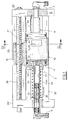
- Figure 1 is a section through the machine on an axial vertical plane, showing it in the configuration for loading the ground product.
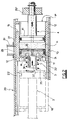
- Figure 2 is a section through the machine on an axial horizontal plane, showing it in the configuration in which the ground product is under maximum compaction.
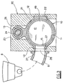
- Figure 3 is a section on the plane III-III of Figure 1.
- Figure 4 is an axial section through the actuator of both the plungers 3 and 4.
- the figures show substantially only those machine members provided for decoction, compression of the ground product and expulsion of this product when spent, the other means, such as those for supplying the ground product and for supplying pressurized steam/water, being any means of known type.
- the invention comprises a movable body 10 having in its interior a cylindrical decoction chamber 11 with two ends (or mouths), namely a first end 11' and an open second end 11''.
- the body 10 is constrained to a fixed structure 20 such that it can move in the direction of the axis of the chamber 11.
- the body 10 has the overall outer shape of a right circular cylinder comprising two opposing prismatic projections 12 on two lateral sides and a substantially cylindrical upper projection 13.
- the structure 20 is roughly of parallelepiped outer shape and in its interior possesses axial cavities of constant cross-section within which the body 10 slides as an exact fit. Specifically, it possesses a central cavity 21 within which the cylindrical part of the body 10 slides, and from which there extend an upper corridor 23 within which the upper projection 13 slides as an exact fit, and two lateral grooves 22 within which the prismatic projections 12 slide as an exact fit.
- Said corridors 21 and 23 and grooves 22 have a length much greater (for example 2-4 times) than the length of the body 10, the body 10 being able only to translate along them.
- a worm 24 is provided extending along the entire length of the structure 20, idly pivoted on the two end vertical walls 25' and 25'' of the structure 20.
- a nut screw 26 fixed within the upper projection 13 engages the worm 24.
- the worm is driven by motor means (not shown) in one direction and the other alternately.
- a first plunger 3 is provided, the plug 31 of which is axially slidable under sealed conditions within the chamber 11.
- the rod of the plunger 3 emerges from the chamber 11 through the first end 11'.
- the plug 31 is axially free relative to the body 10, however is constrained to remain within the chamber 11 in proximity to the first end 11' by virtue of a stop wall 14 located close to the end 11'.
- the rod of the plunger 3 is telescopic and is formed from a portion 33 fixed to the wall 25', and a portion 34 rigid with the plug 31.
- the plug 31 and the relative rod portion 34 are axially free relative to the structure 20.
- a cylindrical spring 35 precompressed between the wall 14 and the end of the portion 34 rearwardly urges the portion 34 so that the plug 31 is normally maintained against the wall 14 in proximity to the end 11'.
- abutment element arranged to halt the rearward travel of the plunger during its return travel.
- Said abutment element is defined by the wall 25' against which the free end of the rod portion 34 abuts.
- a second plunger 4 opposing and located symmetrical to the plunger 3 with its plug 41 slidable under sealed conditions within the chamber 11, it being substantially fixed axially relative to the structure 20 and passing through the second end 11'' of the chamber 11.
- the rod 42 of the plunger 4 is axially constrained to the vertical wall 25''.
- the plungers 3 and 4 comprise internal ducts which connect the active faces of the respective plugs to the steam/hot water source and to the drink delivery outlet respectively.
- each plunger 3 and 4 possesses a thin circular plate 39, 49, which is provided with numerous minuscule holes preventing passage of ground product granules and defines the active face of the respective plug.
- each plate 39, 49 there is formed behind each plate 39, 49 a narrow circular chamber 53 closed on one side by the respective perforated plate 39, 49 ( Figure 4).
- the chamber 53 of the plug 31 communicates with an axial channel internal to the rod portion 34, within which the other rod portion 33 slides under sealed conditions.
- the channel 37 communicates with a further thinner axial channel 36 within the portion 33.
- the channel 36 terminates at the rear end of the portion 33 to which there is connected a conduit 9 connected to a pressurized steam/hot water source (not shown).
- the chamber 53 of the plug 41 communicates with an axial channel 47 within the rod 42 which opens at the free end of this latter.
- This end is connected to a drink outlet conduit 7 conveying the drink produced in the decoction chamber 11 to the user.
- an aperture 15 through which the ground product passes into the chamber 11.
- the aperture 15 is in a position axial to the chamber 11 so as to communicate with that chamber portion lying between the two plugs 31 and 41 when the plug 41 is positioned at the second end 11'' ( Figure 1).
- the plug 41 passes beyond said aperture 15 and hence that chamber portion lying between the two plugs 31 and 41 does not communicate with said aperture 15.
- the aperture 15 is positioned a short distance from the end 11''.
- an aperture 28 for passage of the ground product In a lateral wall of the structure 20 against which the outer lateral surface of the body 10 adheringly slides, namely in that wall 27 opposite the prismatic projection 12, there is provided an aperture 28 for passage of the ground product, its passage size being equal to that of the aperture 15.
- a ground product delivery conduit 81 originating from a suitable ground product delivery machine (this machine is of known type and is shown only schematically in Figure 3).
- the aperture 28 is in an axial position so as to mate with the aperture 15 when the body 10 is in an axial position such that the aperture 15 communicates with that chamber portion lying between the two plugs 31 and 41.
- the aperture 28 is positioned towards the centre with respect to the plug 41, either in line with it or at a short distance from it.
- the aperture 28 is closed by the outer lateral surface of the body 10, specifically by the outer face of the projection 12, when the body 10 continues its travel and is close to its outward end-of-travel position.
- both the plugs 31 and 41 lie within the chamber 11 at its respective ends 11' and 11'', that chamber portion between them then having substantially its maximum length.
- the two apertures 15 and 28 are substantially mating and communicate with said chamber portion. The body 10 remains at rest in this position while the machine 8 dispenses ground product, which by gravity fall or by mechanical thrust enters the chamber 11 through the apertures 15 and 28.
- the worm 24 When the predetermined quantity of ground product has been loaded, the worm 24 is rotated so that the body 10 is made to advance along its outward travel, ie towards the plunger 4. During this travel the body 10 drags with it the plug 31, which approaches the plug 41 to compact the ground product within the chamber 11. When this attains the desired maximum degree of compaction (minimum distance between the two plugs) the body 10 is halted (position shown by full lines in Figure 2) and the product undergoes decoction by feeding a predetermined quantity of pressurized steam/hot water through the channel 36, 37.
- This steam/hot water emerges from the plug 31 through the respective plate 39, and passes through the compressed ground product between the two plugs where it decocts the product to form a liquid drink which enters the plug 41 via the plate 49. From here it passes through the channel 47 to the conduit 7 which delivers it to the user. During this stage that chamber portion between the two plugs has moved to the side of the aperture 15, the aperture 28 being closed by the wall 27.
- the body 10 When decoction (and hence delivery of the drink to the user) is complete, the body 10 is made to undergo its return travel by rotating the worm 24 in the reverse direction.
- the plunger 4 can be able to undergo short axial travel and be normally urged against the plunger 3 by a precompressed spring 43.
- the compaction stage then takes place against the opposition provided by this spring, which determines the end of outward travel when a certain compression has been attained. In this manner compaction can be obtained having a constant predetermined value even as the quantity of ground product present in the chamber varies.
- the bodies of the plungers 3 and 4 are constructed of synthetic resin.
- the circular plates 39 and 49 are of metal and have their edge embedded in a peripheral ring 51 comprising radial reinforcement elements 55 for opposing flexure of the plates 39, 49.
- Ribs 54 against which the radial elements 55 rest are provided in the chamber 53.
- the ring 51 is fixed by thermowelding to the front face of the plunger, and more precisely onto an annular rim 52 positioned about the chamber 53. Because of these characteristics the plunger is particularly simple and economical to construct, to the extent that when the filtering plates 36, 49 or the channels 37, 47 become blocked it is more convenient and simple to change the entire plunger by replacing it with a new one.
Landscapes
- Engineering & Computer Science (AREA)
- Mechanical Engineering (AREA)
- Food Science & Technology (AREA)
- Apparatus For Making Beverages (AREA)
- Tea And Coffee (AREA)
Abstract
Description
- This invention relates to an automatic machine for making espresso coffee or similar drinks, in which the drink is obtained by introducing the ground coffee or other ground product into a decoction chamber, compressing this ground product and then passing pressurized steam/hot water through it.
- Typically the machine of the invention is intended as an automatic distributor for such drinks, in particular coffee.
- The object of the present invention is to improve the means provided for compressing the ground product in the decoction chamber and for then discharging the spent product, by providing constructionally simple means of reliable and fast operation.
- To this end, the invention provides a body with a cylindrical decoction chamber in its interior and able to move in the direction of the axis of this chamber. With the chamber there are associated two plungers, one of which is constrained to the chamber such that its plug cannot leave the chamber but remains resting against a stop wall at a first end of the chamber; the second plunger is fixed to a fixed structure and enters and leaves the chamber via its second end. The body is moved with outward and return travel alternately.
- During its outward travel, the movable body drags the first plunger towards the second plunger, both within said chamber, so as to compact the product in the chamber to the required extent and hence effect decoction of the product to obtain the drink, by means of steam/hot water passing through said compacted product. During the return travel the second plunger withdraws from the chamber until it lies at a distance from the movable body. Simultaneously the first plunger is moved until it abuts against a suitable stop element so that it stops and, by sliding within the chamber, expels the spent product.
- The invention is described in detail hereinafter with the aid of the accompanying figures, which illustrate a preferred but not exclusive embodiment thereof.
- Figure 1 is a section through the machine on an axial vertical plane, showing it in the configuration for loading the ground product.
- Figure 2 is a section through the machine on an axial horizontal plane, showing it in the configuration in which the ground product is under maximum compaction.
- Figure 3 is a section on the plane III-III of Figure 1.
- Figure 4 is an axial section through the actuator of both the
plungers - The figures show substantially only those machine members provided for decoction, compression of the ground product and expulsion of this product when spent, the other means, such as those for supplying the ground product and for supplying pressurized steam/water, being any means of known type.
- The invention comprises a
movable body 10 having in its interior acylindrical decoction chamber 11 with two ends (or mouths), namely a first end 11' and an open second end 11''. - The
body 10 is constrained to afixed structure 20 such that it can move in the direction of the axis of thechamber 11. Specifically, thebody 10 has the overall outer shape of a right circular cylinder comprising two opposingprismatic projections 12 on two lateral sides and a substantially cylindricalupper projection 13. Thestructure 20 is roughly of parallelepiped outer shape and in its interior possesses axial cavities of constant cross-section within which thebody 10 slides as an exact fit. Specifically, it possesses acentral cavity 21 within which the cylindrical part of thebody 10 slides, and from which there extend anupper corridor 23 within which theupper projection 13 slides as an exact fit, and twolateral grooves 22 within which theprismatic projections 12 slide as an exact fit. - Said
corridors grooves 22 have a length much greater (for example 2-4 times) than the length of thebody 10, thebody 10 being able only to translate along them. - With the
body 10 there are associated means for moving it in an axial direction within thestructure 20 with alternately outward and return travel. Specifically, aworm 24 is provided extending along the entire length of thestructure 20, idly pivoted on the two end vertical walls 25' and 25'' of thestructure 20. Anut screw 26 fixed within theupper projection 13 engages theworm 24. The worm is driven by motor means (not shown) in one direction and the other alternately. - A
first plunger 3 is provided, theplug 31 of which is axially slidable under sealed conditions within thechamber 11. The rod of theplunger 3 emerges from thechamber 11 through the first end 11'. Theplug 31 is axially free relative to thebody 10, however is constrained to remain within thechamber 11 in proximity to the first end 11' by virtue of astop wall 14 located close to the end 11'. - The rod of the
plunger 3 is telescopic and is formed from aportion 33 fixed to the wall 25', and aportion 34 rigid with theplug 31. Theplug 31 and therelative rod portion 34 are axially free relative to thestructure 20. Acylindrical spring 35 precompressed between thewall 14 and the end of theportion 34 rearwardly urges theportion 34 so that theplug 31 is normally maintained against thewall 14 in proximity to the end 11'. - With the
plunger 3 there is associated an abutment element arranged to halt the rearward travel of the plunger during its return travel. Said abutment element is defined by the wall 25' against which the free end of therod portion 34 abuts. - There is also provided a
second plunger 4 opposing and located symmetrical to theplunger 3 with itsplug 41 slidable under sealed conditions within thechamber 11, it being substantially fixed axially relative to thestructure 20 and passing through the second end 11'' of thechamber 11. - The rod 42 of the
plunger 4 is axially constrained to the vertical wall 25''. - The
plungers - Specifically, each
plunger circular plate - Within the
plug plate 39, 49 a narrowcircular chamber 53 closed on one side by the respectiveperforated plate 39, 49 (Figure 4). - The
chamber 53 of theplug 31 communicates with an axial channel internal to therod portion 34, within which theother rod portion 33 slides under sealed conditions. Thechannel 37 communicates with a further thinneraxial channel 36 within theportion 33. Thechannel 36 terminates at the rear end of theportion 33 to which there is connected aconduit 9 connected to a pressurized steam/hot water source (not shown). - The
chamber 53 of theplug 41 communicates with an axial channel 47 within the rod 42 which opens at the free end of this latter. - This end is connected to a drink outlet conduit 7 conveying the drink produced in the
decoction chamber 11 to the user. - In the lateral wall of the
body 10 in correspondence with aprismatic projection 12 there is provided anaperture 15 through which the ground product passes into thechamber 11. Theaperture 15 is in a position axial to thechamber 11 so as to communicate with that chamber portion lying between the twoplugs plug 41 is positioned at the second end 11'' (Figure 1). - When the
body 10 reaches its outward end-of-travel position, theplug 41 passes beyond saidaperture 15 and hence that chamber portion lying between the twoplugs aperture 15. Theaperture 15 is positioned a short distance from the end 11''. - In a lateral wall of the
structure 20 against which the outer lateral surface of thebody 10 adheringly slides, namely in thatwall 27 opposite theprismatic projection 12, there is provided anaperture 28 for passage of the ground product, its passage size being equal to that of theaperture 15. Into theaperture 28 there opens a groundproduct delivery conduit 81 originating from a suitable ground product delivery machine (this machine is of known type and is shown only schematically in Figure 3). Theaperture 28 is in an axial position so as to mate with theaperture 15 when thebody 10 is in an axial position such that theaperture 15 communicates with that chamber portion lying between the twoplugs aperture 28 is positioned towards the centre with respect to theplug 41, either in line with it or at a short distance from it. Theaperture 28 is closed by the outer lateral surface of thebody 10, specifically by the outer face of theprojection 12, when thebody 10 continues its travel and is close to its outward end-of-travel position. - The operation of the illustrated means takes place cyclically as follows.
- It will be assumed that initially the
body 10 is at rest in the position for loading the ground product (Figure 1). In this position, both theplugs chamber 11 at its respective ends 11' and 11'', that chamber portion between them then having substantially its maximum length. In addition the twoapertures body 10 remains at rest in this position while themachine 8 dispenses ground product, which by gravity fall or by mechanical thrust enters thechamber 11 through theapertures - When the predetermined quantity of ground product has been loaded, the
worm 24 is rotated so that thebody 10 is made to advance along its outward travel, ie towards theplunger 4. During this travel thebody 10 drags with it theplug 31, which approaches theplug 41 to compact the ground product within thechamber 11. When this attains the desired maximum degree of compaction (minimum distance between the two plugs) thebody 10 is halted (position shown by full lines in Figure 2) and the product undergoes decoction by feeding a predetermined quantity of pressurized steam/hot water through thechannel plug 31 through therespective plate 39, and passes through the compressed ground product between the two plugs where it decocts the product to form a liquid drink which enters theplug 41 via theplate 49. From here it passes through the channel 47 to the conduit 7 which delivers it to the user. During this stage that chamber portion between the two plugs has moved to the side of theaperture 15, theaperture 28 being closed by thewall 27. - When decoction (and hence delivery of the drink to the user) is complete, the
body 10 is made to undergo its return travel by rotating theworm 24 in the reverse direction. - Initially the
body 10 and theplug 31 withdraw from theplunger 4 while therod portion 33 enters theportion 34. Therod portion 34 then halts against the wall 25' while thebody 10 continues its return travel. Hence theplug 31, overcoming the thrust of thespring 35, slides along the whole length of thechamber 11 to hence expel the spent ground product from the chamber (position shown by dashed lines in Figure 2). After this the outward travel begins, theplug 31 urged by thespring 35 returning towards the end end 11' and against thewall 14. When thebody 10 reaches said ground product loading position, it stops and the aforedescribed cycle is repeated in the same manner. All the described operations are controlled automatically in sequence by a control system using normal means and methods. - Advantageously the
plunger 4 can be able to undergo short axial travel and be normally urged against theplunger 3 by aprecompressed spring 43. The compaction stage then takes place against the opposition provided by this spring, which determines the end of outward travel when a certain compression has been attained. In this manner compaction can be obtained having a constant predetermined value even as the quantity of ground product present in the chamber varies. - In addition, according to the present invention the bodies of the
plungers circular plates peripheral ring 51 comprisingradial reinforcement elements 55 for opposing flexure of theplates -
Ribs 54 against which theradial elements 55 rest are provided in thechamber 53. - The
ring 51 is fixed by thermowelding to the front face of the plunger, and more precisely onto anannular rim 52 positioned about thechamber 53. Because of these characteristics the plunger is particularly simple and economical to construct, to the extent that when thefiltering plates channels 37, 47 become blocked it is more convenient and simple to change the entire plunger by replacing it with a new one.
Claims (6)
- An automatic machine for making espresso coffee or similar drinks, in which the drink is obtained by introducing the ground coffee or other product into a decoction chamber, then compacting this ground product and passing pressurized steam/hot water through it, characterised by comprising:
a movable body (10) having a cylindrical decoction chamber (11) with a first end (11') and an open second end (11''), said chamber (11) being in communication with means (8) for supplying the ground product, and said movable body (10) being constrained to a fixed structure in a manner able to move in the direction of the axis of the chamber (11);
means (24, 26) for moving the movable body (10) in said axial direction with outward and return travel alternately;
a first plunger (3) axially slidable under sealed conditions within the chamber (11) and having its plug (31) retained by stop means (14) positioned at said first end (11') so that it cannot leave through said first end (11'), said plug (31) being axially movable relative to the fixed structure (20);
a second plunger (4) axially slidable under sealed conditions within the chamber (11) and opposing the first plunger (3), its plug (41) being able to pass through the second end (11'') of the chamber (11), said second plunger (4) being substantially fixed axially;
said plungers (3) and (4) having internal ducts for communication between the active faces of the respective plugs (31, 41) and, respectively, the steam/hot water source and the drink delivery outlet (7);
the return travel of the movable body (10) causing the second plunger (4) to withdraw from the chamber (11) and the first plunger (3) to halt against the abutment element (25') and then slide within the chamber (11) along its entire length;
the outward travel of the movable body (10) causing the first plunger (3) to be dragged and the second plunger (4) to penetrate into the chamber (11) with mutual approach of the two plugs (31) and (41). - A machine as claimed in claim 1, characterised by comprising, for passage of the ground product into the chamber (11), an aperture (15) provided in the lateral wall of the movable body (10) in an axial position such as to communicate with that chamber portion lying between the two plugs (31) and (41) when the plug (41) of the second plunger (4) lies at the second end (11'') of the chamber (11), the plug (41) of the second plunger (4) passing beyond said aperture (15) when the movable body (10) reaches its outward travel limit, said aperture (15) being in communication with the means (8) for supplying the ground product.
- A machine as claimed in claim 2, characterised in that said fixed structure (20) comprises a wall (27) against which there adheringly slides the outer lateral surface of the movable body (10) and which contains a second ground product passage aperture 28 into which a ground product delivery conduit (81) opens, said second aperture (28) being provided in an axial position such as to mate with the first aperture (15) when the movable body (10) is in a position such that its aperture (15) communicates with that chamber portion lying between the two plugs (31) and (41), and being closed by the outer lateral surface of the movable body (10) when this is close to its outward end of travel position.
- A machine as claimed in claim 1, characterised in that the first plunger (3) has a telescopic rod with, rigid with the plug (31), a portion (34) urged by spring means (35) rearwards relative to the movable body (10) in such a manner as to maintain the plug (31) normally at the first end (11') of the chamber (11), the free end of said portion (34) abutting against the abutment element (25') to halt the first plunger (3) during its return travel.
- A machine as claimed in claim 1, characterised in that the second plunger (4) can undergo short axial travel and is normally urged towards the other plunger (3) by an elastic spring (43) the degree of maximum compression of which determines the end of outward travel.
- A machine as claimed in claim 1, characterised in that the plugs (31) and (41) comprise circular filtering plates (39), (49), the end of which is joined to a peripheral ring (51) fixed to the plug by welding.
Applications Claiming Priority (2)
| Application Number | Priority Date | Filing Date | Title |
|---|---|---|---|
| ITRE930087A IT1262342B (en) | 1993-12-20 | 1993-12-20 | AUTOMATIC MACHINE FOR MAKING ESPRESSO COFFEE OR ANALOGUE BEVERAGES. |
| ITRE930087 | 1993-12-20 |
Publications (2)
| Publication Number | Publication Date |
|---|---|
| EP0659377A1 true EP0659377A1 (en) | 1995-06-28 |
| EP0659377B1 EP0659377B1 (en) | 1997-03-12 |
Family
ID=11398481
Family Applications (1)
| Application Number | Title | Priority Date | Filing Date |
|---|---|---|---|
| EP94203543A Expired - Lifetime EP0659377B1 (en) | 1993-12-20 | 1994-12-06 | Automatic machine for making espresso coffee or similar drinks |
Country Status (5)
| Country | Link |
|---|---|
| EP (1) | EP0659377B1 (en) |
| AT (1) | ATE149810T1 (en) |
| DE (1) | DE69402040T2 (en) |
| ES (1) | ES2102142T3 (en) |
| IT (1) | IT1262342B (en) |
Cited By (12)
| Publication number | Priority date | Publication date | Assignee | Title |
|---|---|---|---|---|
| EP0931491A1 (en) * | 1998-01-26 | 1999-07-28 | SCHMED, Arthur | Coffee machine |
| EP0993800A1 (en) * | 1998-10-16 | 2000-04-19 | Wmf Württembergische Metallwarenfabrik Ag | Coffee machine |
| EP1059055A1 (en) * | 1999-06-09 | 2000-12-13 | Macco S.p.A. | Working assembly for automatic machines for preparing infusions such as coffee or the like |
| WO2001091620A1 (en) * | 2000-05-31 | 2001-12-06 | Rancilio Macchine Per Caffe' S.P.A. | Coffee making machine |
| WO2002009563A1 (en) * | 2000-08-02 | 2002-02-07 | Rolland Versini | Percolator unit with mobile infusion chamber and detachable without using tools |
| WO2003075725A1 (en) * | 2002-03-08 | 2003-09-18 | Azkoyen Industrial, S.A. | Automated coffee brewing device |
| EP1800575A1 (en) * | 2005-12-23 | 2007-06-27 | RANCILIO MACCHINE PER CAFFE' S.p.A. | Infusion unit |
| EP1900313A1 (en) * | 2006-09-16 | 2008-03-19 | WIK Far East Ltd. | Brewing unit for a coffee machine and coffee machine with such a brewing unit |
| EP2213210A1 (en) * | 2009-02-02 | 2010-08-04 | WIK Far East Ltd. | Brewing unit |
| WO2012084667A1 (en) * | 2010-12-22 | 2012-06-28 | BSH Bosch und Siemens Hausgeräte GmbH | Fully automatic coffee machine having a spindle drive |
| US10537203B2 (en) | 2012-11-16 | 2020-01-21 | J.M. De Jong Duke Automatenfabriek B.V. | Apparatus for preparing a beverage and a decoction device |
| US11297973B2 (en) | 2017-10-20 | 2022-04-12 | J.M. De Jong Duke Automatenfabriek B.V. | Decoction device and extraction apparatus |
Families Citing this family (3)
| Publication number | Priority date | Publication date | Assignee | Title |
|---|---|---|---|---|
| DE202007001176U1 (en) | 2007-01-26 | 2008-06-26 | Wik Far East Ltd. | Brewing unit for a coffee machine and coffee machine |
| DE202007001174U1 (en) | 2007-01-26 | 2008-06-19 | Wik Far East Ltd. | coffee machine |
| DE202007005791U1 (en) | 2007-04-21 | 2008-08-21 | Wik Far East Ltd. | Brewing unit for a coffee machine and coffee machine with such a brewing unit |
Citations (6)
| Publication number | Priority date | Publication date | Assignee | Title |
|---|---|---|---|---|
| BE745939A (en) * | 1969-03-24 | 1970-07-16 | Cianetti Massimo | MACHINE FOR PREPARING INFUSIONS, ESPECIALLY EXPRESS COFFEE |
| EP0202517A1 (en) * | 1985-05-07 | 1986-11-26 | IN ALBON, Jean-Paul | Automatic coffee maker |
| EP0299399A2 (en) * | 1987-07-17 | 1989-01-18 | Sistar Sa | Device for brewing coffee |
| EP0309780A1 (en) * | 1987-09-07 | 1989-04-05 | Vincenzo Cinoni | Automatic infusing group for espresso coffee machines |
| EP0484277A1 (en) * | 1990-10-25 | 1992-05-06 | Dominique Armellin Bucovineanu | Automatic machine for preparing coffee infusions and method for performing the same |
| EP0528758A1 (en) * | 1991-07-30 | 1993-02-24 | Sintra Holding Ag | Device for the expulsion of the exhausted infusion substance from the brewing unit of a coffee machine |
-
1993
- 1993-12-20 IT ITRE930087A patent/IT1262342B/en active IP Right Grant
-
1994
- 1994-12-06 DE DE69402040T patent/DE69402040T2/en not_active Expired - Fee Related
- 1994-12-06 ES ES94203543T patent/ES2102142T3/en not_active Expired - Lifetime
- 1994-12-06 EP EP94203543A patent/EP0659377B1/en not_active Expired - Lifetime
- 1994-12-06 AT AT94203543T patent/ATE149810T1/en not_active IP Right Cessation
Patent Citations (6)
| Publication number | Priority date | Publication date | Assignee | Title |
|---|---|---|---|---|
| BE745939A (en) * | 1969-03-24 | 1970-07-16 | Cianetti Massimo | MACHINE FOR PREPARING INFUSIONS, ESPECIALLY EXPRESS COFFEE |
| EP0202517A1 (en) * | 1985-05-07 | 1986-11-26 | IN ALBON, Jean-Paul | Automatic coffee maker |
| EP0299399A2 (en) * | 1987-07-17 | 1989-01-18 | Sistar Sa | Device for brewing coffee |
| EP0309780A1 (en) * | 1987-09-07 | 1989-04-05 | Vincenzo Cinoni | Automatic infusing group for espresso coffee machines |
| EP0484277A1 (en) * | 1990-10-25 | 1992-05-06 | Dominique Armellin Bucovineanu | Automatic machine for preparing coffee infusions and method for performing the same |
| EP0528758A1 (en) * | 1991-07-30 | 1993-02-24 | Sintra Holding Ag | Device for the expulsion of the exhausted infusion substance from the brewing unit of a coffee machine |
Cited By (20)
| Publication number | Priority date | Publication date | Assignee | Title |
|---|---|---|---|---|
| EP0931491A1 (en) * | 1998-01-26 | 1999-07-28 | SCHMED, Arthur | Coffee machine |
| EP0993800A1 (en) * | 1998-10-16 | 2000-04-19 | Wmf Württembergische Metallwarenfabrik Ag | Coffee machine |
| EP1059055A1 (en) * | 1999-06-09 | 2000-12-13 | Macco S.p.A. | Working assembly for automatic machines for preparing infusions such as coffee or the like |
| US6634280B2 (en) | 2000-05-31 | 2003-10-21 | Rancilio Macchine Per Caffe' S.P.A. | Coffee making machine |
| WO2001091620A1 (en) * | 2000-05-31 | 2001-12-06 | Rancilio Macchine Per Caffe' S.P.A. | Coffee making machine |
| GB2369557B (en) * | 2000-05-31 | 2004-10-06 | Rancilio Macchine Caffe | Infusion group for a machine for preparing infusions |
| GB2369557A (en) * | 2000-05-31 | 2002-06-05 | Rancilio Macchine Caffe | coffee making machine |
| US6827003B2 (en) | 2000-08-02 | 2004-12-07 | Rolland Versini | Percolator unit with mobile infusion chamber and detachable without using tools |
| FR2812528A1 (en) * | 2000-08-02 | 2002-02-08 | Rolland Versini | PERCOLATOR GROUP WITH MOBILE AND DISASSEMBLABLE INFUSION CHAMBER WITHOUT TOOLS |
| WO2002009563A1 (en) * | 2000-08-02 | 2002-02-07 | Rolland Versini | Percolator unit with mobile infusion chamber and detachable without using tools |
| WO2003075725A1 (en) * | 2002-03-08 | 2003-09-18 | Azkoyen Industrial, S.A. | Automated coffee brewing device |
| EP1800575A1 (en) * | 2005-12-23 | 2007-06-27 | RANCILIO MACCHINE PER CAFFE' S.p.A. | Infusion unit |
| WO2007072453A1 (en) * | 2005-12-23 | 2007-06-28 | Rancilio Macchine Per Caffe' S.P.A. | Infusion unit |
| US8225709B2 (en) | 2005-12-23 | 2012-07-24 | Rancilio Macchine Per Caffe' S.P.A. | Infusion unit for infusion preparation, infusion machine, device for ejection of exhausted infusion powder and method for making the same |
| EP1900313A1 (en) * | 2006-09-16 | 2008-03-19 | WIK Far East Ltd. | Brewing unit for a coffee machine and coffee machine with such a brewing unit |
| EP2213210A1 (en) * | 2009-02-02 | 2010-08-04 | WIK Far East Ltd. | Brewing unit |
| CN101791197B (en) * | 2009-02-02 | 2012-07-25 | 伟嘉电业有限公司 | Brewing unit |
| WO2012084667A1 (en) * | 2010-12-22 | 2012-06-28 | BSH Bosch und Siemens Hausgeräte GmbH | Fully automatic coffee machine having a spindle drive |
| US10537203B2 (en) | 2012-11-16 | 2020-01-21 | J.M. De Jong Duke Automatenfabriek B.V. | Apparatus for preparing a beverage and a decoction device |
| US11297973B2 (en) | 2017-10-20 | 2022-04-12 | J.M. De Jong Duke Automatenfabriek B.V. | Decoction device and extraction apparatus |
Also Published As
| Publication number | Publication date |
|---|---|
| ITRE930087A1 (en) | 1995-06-20 |
| IT1262342B (en) | 1996-06-19 |
| DE69402040T2 (en) | 1997-06-19 |
| ITRE930087A0 (en) | 1993-12-20 |
| DE69402040D1 (en) | 1997-04-17 |
| EP0659377B1 (en) | 1997-03-12 |
| ATE149810T1 (en) | 1997-03-15 |
| ES2102142T3 (en) | 1997-07-16 |
Similar Documents
| Publication | Publication Date | Title |
|---|---|---|
| EP0659377A1 (en) | Automatic machine for making espresso coffee or similar drinks | |
| US3760712A (en) | Mechanical unit for brewing infusions, more particularly espresso-coffee | |
| EP1121882B1 (en) | Automatic unit for preparing espresso coffee | |
| US4852472A (en) | Apparatus for preparing coffee | |
| CZ70693A3 (en) | Scalding device for a coffee maker and method of making coffee | |
| EP0236391B1 (en) | Automatic machine for preparing espresso coffee | |
| AU2001260525B2 (en) | Coffee making machine | |
| EP0084291A1 (en) | Dosing machine for the filling with deformable foodstuff of permanent-shaped cavities, and its use | |
| AU2001260525A1 (en) | Coffee making machine | |
| US4850839A (en) | Extrusion apparatus | |
| EP0647515A1 (en) | Method for forming synthetic resins and apparatus therefor | |
| EP0078926B1 (en) | Method for mold injection | |
| ITTO20080361A1 (en) | INFUSER GROUP FOR THE PRODUCTION OF DRINKS | |
| US4092118A (en) | Mixing head | |
| CN109124354B (en) | Coffee extraction device, coffee machine and automatic coffee vending machine | |
| US3234598A (en) | Apparatus for pressing slurries | |
| US5182120A (en) | Device for dosing into moulds | |
| US3813014A (en) | Injection moulding machine | |
| GB1565406A (en) | Machine for automatically preparing infusion in particular of coffee | |
| EP0217198B1 (en) | Automatic coffee-making machine | |
| US7621212B2 (en) | Piston for a beverage infusion automatic machine | |
| US2738550A (en) | Machine for dispensing predetermined quantities of material in loose or compressed form | |
| US3854397A (en) | Refuse compacting device | |
| EP0571334A1 (en) | Apparatus for continuously injecting elastomeric and plastic materials | |
| CA2170655C (en) | Dual hydraulic cylinder compacting device |
Legal Events
| Date | Code | Title | Description |
|---|---|---|---|
| PUAI | Public reference made under article 153(3) epc to a published international application that has entered the european phase |
Free format text: ORIGINAL CODE: 0009012 |
|
| AK | Designated contracting states |
Kind code of ref document: A1 Designated state(s): AT BE CH DE DK ES FR GB GR IE IT LI LU MC NL PT SE |
|
| RAX | Requested extension states of the european patent have changed |
Free format text: LT PAYMENT 941206;SI PAYMENT 941206 |
|
| 17P | Request for examination filed |
Effective date: 19951227 |
|
| 17Q | First examination report despatched |
Effective date: 19960126 |
|
| GRAG | Despatch of communication of intention to grant |
Free format text: ORIGINAL CODE: EPIDOS AGRA |
|
| GRAH | Despatch of communication of intention to grant a patent |
Free format text: ORIGINAL CODE: EPIDOS IGRA |
|
| GRAH | Despatch of communication of intention to grant a patent |
Free format text: ORIGINAL CODE: EPIDOS IGRA |
|
| GRAA | (expected) grant |
Free format text: ORIGINAL CODE: 0009210 |
|
| AK | Designated contracting states |
Kind code of ref document: B1 Designated state(s): AT BE CH DE DK ES FR GB GR IE IT LI LU MC NL PT SE |
|
| AX | Request for extension of the european patent |
Free format text: LT PAYMENT 941206;SI PAYMENT 941206 |
|
| PG25 | Lapsed in a contracting state [announced via postgrant information from national office to epo] |
Ref country code: NL Free format text: LAPSE BECAUSE OF FAILURE TO SUBMIT A TRANSLATION OF THE DESCRIPTION OR TO PAY THE FEE WITHIN THE PRESCRIBED TIME-LIMIT Effective date: 19970312 Ref country code: GR Free format text: LAPSE BECAUSE OF FAILURE TO SUBMIT A TRANSLATION OF THE DESCRIPTION OR TO PAY THE FEE WITHIN THE PRESCRIBED TIME-LIMIT Effective date: 19970312 Ref country code: DK Effective date: 19970312 Ref country code: BE Effective date: 19970312 Ref country code: AT Effective date: 19970312 |
|
| REF | Corresponds to: |
Ref document number: 149810 Country of ref document: AT Date of ref document: 19970315 Kind code of ref document: T |
|
| REG | Reference to a national code |
Ref country code: CH Ref legal event code: NV Representative=s name: ISLER & PEDRAZZINI AG Ref country code: CH Ref legal event code: EP |
|
| REF | Corresponds to: |
Ref document number: 69402040 Country of ref document: DE Date of ref document: 19970417 |
|
| ET | Fr: translation filed | ||
| REG | Reference to a national code |
Ref country code: IE Ref legal event code: FG4D Free format text: 72744 |
|
| PG25 | Lapsed in a contracting state [announced via postgrant information from national office to epo] |
Ref country code: SE Effective date: 19970612 |
|
| REG | Reference to a national code |
Ref country code: PT Ref legal event code: SC4A Free format text: AVAILABILITY OF NATIONAL TRANSLATION Effective date: 19970402 |
|
| REG | Reference to a national code |
Ref country code: ES Ref legal event code: FG2A Ref document number: 2102142 Country of ref document: ES Kind code of ref document: T3 |
|
| NLV1 | Nl: lapsed or annulled due to failure to fulfill the requirements of art. 29p and 29m of the patents act | ||
| PG25 | Lapsed in a contracting state [announced via postgrant information from national office to epo] |
Ref country code: LU Free format text: LAPSE BECAUSE OF NON-PAYMENT OF DUE FEES Effective date: 19971206 Ref country code: IE Free format text: LAPSE BECAUSE OF NON-PAYMENT OF DUE FEES Effective date: 19971206 |
|
| PLBE | No opposition filed within time limit |
Free format text: ORIGINAL CODE: 0009261 |
|
| STAA | Information on the status of an ep patent application or granted ep patent |
Free format text: STATUS: NO OPPOSITION FILED WITHIN TIME LIMIT |
|
| 26N | No opposition filed | ||
| PG25 | Lapsed in a contracting state [announced via postgrant information from national office to epo] |
Ref country code: MC Free format text: LAPSE BECAUSE OF NON-PAYMENT OF DUE FEES Effective date: 19980630 |
|
| REG | Reference to a national code |
Ref country code: GB Ref legal event code: IF02 |
|
| REG | Reference to a national code |
Ref country code: CH Ref legal event code: PCAR Free format text: ISLER & PEDRAZZINI AG;POSTFACH 1772;8027 ZUERICH (CH) |
|
| PGFP | Annual fee paid to national office [announced via postgrant information from national office to epo] |
Ref country code: ES Payment date: 20071207 Year of fee payment: 14 |
|
| PGFP | Annual fee paid to national office [announced via postgrant information from national office to epo] |
Ref country code: GB Payment date: 20071129 Year of fee payment: 14 |
|
| PGFP | Annual fee paid to national office [announced via postgrant information from national office to epo] |
Ref country code: PT Payment date: 20071123 Year of fee payment: 14 |
|
| PGFP | Annual fee paid to national office [announced via postgrant information from national office to epo] |
Ref country code: FR Payment date: 20071228 Year of fee payment: 14 |
|
| PGFP | Annual fee paid to national office [announced via postgrant information from national office to epo] |
Ref country code: CH Payment date: 20081127 Year of fee payment: 15 |
|
| PGFP | Annual fee paid to national office [announced via postgrant information from national office to epo] |
Ref country code: DE Payment date: 20090102 Year of fee payment: 15 |
|
| REG | Reference to a national code |
Ref country code: PT Ref legal event code: MM4A Free format text: LAPSE DUE TO NON-PAYMENT OF FEES Effective date: 20090608 |
|
| GBPC | Gb: european patent ceased through non-payment of renewal fee |
Effective date: 20081206 |
|
| PG25 | Lapsed in a contracting state [announced via postgrant information from national office to epo] |
Ref country code: PT Free format text: LAPSE BECAUSE OF NON-PAYMENT OF DUE FEES Effective date: 20090608 Ref country code: IT Free format text: LAPSE BECAUSE OF NON-PAYMENT OF DUE FEES Effective date: 20071206 |
|
| REG | Reference to a national code |
Ref country code: FR Ref legal event code: ST Effective date: 20090831 |
|
| PG25 | Lapsed in a contracting state [announced via postgrant information from national office to epo] |
Ref country code: GB Free format text: LAPSE BECAUSE OF NON-PAYMENT OF DUE FEES Effective date: 20081206 |
|
| REG | Reference to a national code |
Ref country code: ES Ref legal event code: FD2A Effective date: 20081209 |
|
| PG25 | Lapsed in a contracting state [announced via postgrant information from national office to epo] |
Ref country code: FR Free format text: LAPSE BECAUSE OF NON-PAYMENT OF DUE FEES Effective date: 20081231 Ref country code: ES Free format text: LAPSE BECAUSE OF NON-PAYMENT OF DUE FEES Effective date: 20081209 |
|
| REG | Reference to a national code |
Ref country code: CH Ref legal event code: PL |
|
| PG25 | Lapsed in a contracting state [announced via postgrant information from national office to epo] |
Ref country code: LI Free format text: LAPSE BECAUSE OF NON-PAYMENT OF DUE FEES Effective date: 20091231 Ref country code: CH Free format text: LAPSE BECAUSE OF NON-PAYMENT OF DUE FEES Effective date: 20091231 |
|
| PG25 | Lapsed in a contracting state [announced via postgrant information from national office to epo] |
Ref country code: DE Free format text: LAPSE BECAUSE OF NON-PAYMENT OF DUE FEES Effective date: 20100701 |
|
| PGFP | Annual fee paid to national office [announced via postgrant information from national office to epo] |
Ref country code: IT Payment date: 20091217 Year of fee payment: 16 |
|
| PGRI | Patent reinstated in contracting state [announced from national office to epo] |
Ref country code: IT Effective date: 20110616 |
|
| PGRI | Patent reinstated in contracting state [announced from national office to epo] |
Ref country code: IT Effective date: 20110616 |