EP0659326B1 - Time alignment of transmission in a down-link of a cdma system - Google Patents
Time alignment of transmission in a down-link of a cdma system Download PDFInfo
- Publication number
- EP0659326B1 EP0659326B1 EP94919058A EP94919058A EP0659326B1 EP 0659326 B1 EP0659326 B1 EP 0659326B1 EP 94919058 A EP94919058 A EP 94919058A EP 94919058 A EP94919058 A EP 94919058A EP 0659326 B1 EP0659326 B1 EP 0659326B1
- Authority
- EP
- European Patent Office
- Prior art keywords
- base station
- mobile station
- signal
- time
- station
- Prior art date
- Legal status (The legal status is an assumption and is not a legal conclusion. Google has not performed a legal analysis and makes no representation as to the accuracy of the status listed.)
- Expired - Lifetime
Links
- 230000005540 biological transmission Effects 0.000 title claims description 34
- 238000004891 communication Methods 0.000 claims description 54
- 238000000034 method Methods 0.000 claims description 36
- 238000005259 measurement Methods 0.000 claims description 21
- 230000003139 buffering effect Effects 0.000 claims description 9
- 230000008859 change Effects 0.000 claims description 4
- 230000000737 periodic effect Effects 0.000 claims description 4
- 230000000977 initiatory effect Effects 0.000 claims description 3
- 230000008054 signal transmission Effects 0.000 claims description 3
- 230000001413 cellular effect Effects 0.000 description 13
- 230000001360 synchronised effect Effects 0.000 description 13
- 230000001934 delay Effects 0.000 description 9
- 230000007480 spreading Effects 0.000 description 7
- 238000001228 spectrum Methods 0.000 description 6
- 238000011156 evaluation Methods 0.000 description 5
- 230000003111 delayed effect Effects 0.000 description 4
- 238000010586 diagram Methods 0.000 description 4
- 230000002596 correlated effect Effects 0.000 description 3
- 230000000875 corresponding effect Effects 0.000 description 3
- 239000006185 dispersion Substances 0.000 description 3
- 101100167667 Arabidopsis thaliana CML24 gene Proteins 0.000 description 2
- 230000000295 complement effect Effects 0.000 description 2
- 239000002131 composite material Substances 0.000 description 2
- 230000003247 decreasing effect Effects 0.000 description 2
- 230000006870 function Effects 0.000 description 2
- 230000002452 interceptive effect Effects 0.000 description 2
- 238000012986 modification Methods 0.000 description 2
- 230000004048 modification Effects 0.000 description 2
- 230000008569 process Effects 0.000 description 2
- IRLPACMLTUPBCL-KQYNXXCUSA-N 5'-adenylyl sulfate Chemical compound C1=NC=2C(N)=NC=NC=2N1[C@@H]1O[C@H](COP(O)(=O)OS(O)(=O)=O)[C@@H](O)[C@H]1O IRLPACMLTUPBCL-KQYNXXCUSA-N 0.000 description 1
- 101100438241 Arabidopsis thaliana CAM5 gene Proteins 0.000 description 1
- 238000013459 approach Methods 0.000 description 1
- 238000007630 basic procedure Methods 0.000 description 1
- 230000010267 cellular communication Effects 0.000 description 1
- 238000001514 detection method Methods 0.000 description 1
- 238000006073 displacement reaction Methods 0.000 description 1
- 238000005516 engineering process Methods 0.000 description 1
- 238000010295 mobile communication Methods 0.000 description 1
- 230000008447 perception Effects 0.000 description 1
- 230000010363 phase shift Effects 0.000 description 1
- 238000012545 processing Methods 0.000 description 1
- 230000001105 regulatory effect Effects 0.000 description 1
- 230000004044 response Effects 0.000 description 1
- 238000007493 shaping process Methods 0.000 description 1
Images


Classifications
-
- H—ELECTRICITY
- H04—ELECTRIC COMMUNICATION TECHNIQUE
- H04J—MULTIPLEX COMMUNICATION
- H04J3/00—Time-division multiplex systems
- H04J3/02—Details
- H04J3/06—Synchronising arrangements
- H04J3/0635—Clock or time synchronisation in a network
- H04J3/0682—Clock or time synchronisation in a network by delay compensation, e.g. by compensation of propagation delay or variations thereof, by ranging
-
- H—ELECTRICITY
- H04—ELECTRIC COMMUNICATION TECHNIQUE
- H04L—TRANSMISSION OF DIGITAL INFORMATION, e.g. TELEGRAPHIC COMMUNICATION
- H04L7/00—Arrangements for synchronising receiver with transmitter
- H04L7/0016—Arrangements for synchronising receiver with transmitter correction of synchronization errors
- H04L7/005—Correction by an elastic buffer
-
- H—ELECTRICITY
- H04—ELECTRIC COMMUNICATION TECHNIQUE
- H04L—TRANSMISSION OF DIGITAL INFORMATION, e.g. TELEGRAPHIC COMMUNICATION
- H04L7/00—Arrangements for synchronising receiver with transmitter
- H04L7/0016—Arrangements for synchronising receiver with transmitter correction of synchronization errors
- H04L7/0033—Correction by delay
-
- H—ELECTRICITY
- H04—ELECTRIC COMMUNICATION TECHNIQUE
- H04W—WIRELESS COMMUNICATION NETWORKS
- H04W36/00—Hand-off or reselection arrangements
- H04W36/16—Performing reselection for specific purposes
- H04W36/18—Performing reselection for specific purposes for allowing seamless reselection, e.g. soft reselection
Definitions
- the present invention relates to the use of Code Division Multiple Access (CDMA) communications techniques in cellular radio telephone communication systems, and more particularly, to a method using a Direct Sequence-Code Division Multiple Access (DS-CDMA) communication technique for aligning transmissions in macro-diversity down-links from more than one base station to the same mobile station.
- CDMA Code Division Multiple Access
- DS-CDMA Direct Sequence-Code Division Multiple Access
- CDMA or spread spectrum communications have been in existence since the days of World War II. Early applications were predominantly military oriented. However, today there has been an increasing interest in using spread spectrum systems in commercial applications. Some examples include digital cellular radio, land mobile radio, and indoor and outdoor personal communication networks, generically referred to as cellular systems herein.
- FDMA Frequency Division Multiple Access
- TDMA Time Division Multiple Access
- a channel In TDMA systems, a channel consists of a time slot in a periodic train of time intervals over the same frequency. Each period of time slots is called a frame. A given signal's energy is confined to one of these time slots. Adjacent channel interference is limited by the use of a time gate or other synchronization element that only passes signal energy received at the proper time. Thus, the problem of interference from different relative signal strength levels is reduced. With FDMA or TDMA systems or hybrid FDMA/TDMA systems, the goal is to insure that two potentially interfering signals do not occupy the same frequency at the same time.
- Capacity in a TDMA system is increased by compressing the transmission signal into a shorter time slot.
- the information must be transmitted at a correspondingly faster burst rate which increases the amount of occupied spectrum proportionally.
- time-alignment of mobile stations in an up-link is used to ensure that a base station receives the signal from a mobile station in the assigned TDMA time-slot.
- CDMA Code Division Multiple Access
- European Patent Application 0 522 772 discloses a wireless access telephone-to-telephone network interface structure for CDMA cellular radio telephone systems and is cited as but one example of a CDMA system.
- the informational data stream to be transmitted is impressed upon a much higher rate data stream known as a signature sequence.
- the signature sequence data are binary, providing a bit stream.
- PN pseudo-noise
- the informational data stream and the high bit rate signature sequence stream are combined by multiplying the two bit streams together, assuming the binary values of the two bit streams are represented by +1 or -1.
- This combination of the higher bit rate signal with the lower bit rate data stream is called coding or spreading the informational data stream signal.
- Each informational data stream or channel is allocated a unique spreading code.
- a plurality of coded information signals modulate a radio frequency carrier, for example by quadrature phase shift keying (QPSK), and are jointly received as a composite signal at a receiver.
- QPSK quadrature phase shift keying
- Each of the coded signals overlaps all of the other coded signals, as well as noise-related signals, in both frequency and time. If the receiver is authorized, then the composite signal is correlated with one of the unique codes, and the corresponding information signal can be isolated and decoded.
- One CDMA technique uses a signature sequence to represent one bit of information.
- Receiving the transmitted sequence or its complement indicates whether the information bit is a "0" or "1".
- the signature sequence usually comprises N bits, and each bit is called a "chip”.
- the entire N-chip sequence, or its complement, is referred to as a transmitted symbol.
- the receiver correlates the received signal with the known signature sequence of its own signature sequence generator to produce a normalized value ranging from -1 to +1. When a large positive correlation results, a "0" is detected; when a large negative correlation results, a "1" is detected.
- a CDMA technique called “enhanced CDMA with direct spreading” allows each transmitted sequence to represent more than one bit of information.
- a set of code words typically orthogonal code words or bi-orthogonal code words, is used to code a group of information bits into a much longer code sequence or code symbol.
- a signature sequence or scramble mask is modulo-2 added to the binary code sequence before transmission.
- the known scramble mask is used to descramble the received signal, which is then correlated to all possible code words.
- the code word with the largest correlation value indicates which code word was most likely sent, indicating which information bits were most likely sent.
- One common orthogonal code is the Walsh-Hadamard (WH) code.
- the "information bits" referred to above can also be coded bits, where the code used is a block or convolutional code.
- One or more information bits can form a data symbol.
- the signature sequence or scramble mask can be much longer than a single code sequence, in which case a subsequence of the signature sequence or scramble mask is added to the code sequence.
- Handoff procedure for handing a call link from one cell to another is initiated when the cell site receiver handling the call detects that the received signal strength from a mobile station falls below a predetermined threshold value.
- a low signal strength indication implies that the mobile station is near a cell border.
- the base station queries the system controller to determine whether a neighboring base station receives the mobile telephone signal with better signal strength than the current base station.
- the system controller in response to the base station inquiry sends messages to the neighboring base stations for the handoff requests.
- the neighboring base stations employ scanning receivers which look for the signal of the base station on a specified channel. Should one of the neighboring base stations report an adequate signal level to the system controller, then a handoff is attempted.
- a handoff is initiated when an idle channel from the new base station is selected.
- a control message is sent to the mobile station commanding it to switch from the current channel to a new channel.
- the system controller switches the call link from the first base station to the second base station.
- the call link from the first base station is maintained for a period after initiating and establishing a call link to the second base station. This process is called soft handover through macro-diversity and reduces the perception of the handover due to loss of data during the actual handover. Macro-diversity may be implemented for reasons other than handover, e.g., in noisy environments to assure good signal quality.
- Macro-diversity in a CDMA system can be achieved with synchronized base stations.
- the base stations can be synchronized with all base station digital transmissions being referenced to a common CDMA system-wide time scale that uses the Global Positioning System (GPS) time scale, which is traceable to and synchronous with Universal Coordinated Time (UTC).
- GPS Global Positioning System
- UTC Universal Coordinated Time
- European Patent Application 0 335 846 relates to a cellular digital mobile radio system with plural base station transmitters within a single cell.
- the same message information is digitally modulated by the different base station transmitters within a single cell to a given mobile station with a mutual transmission time shift.
- the transmission time shift is selected individually for each mobile station such that the corresponding digitally modulated radio signals with the same message information to a given station from different base station transmitters arrives practically simultaneously at the mobile station.
- This system does not involve the establishment of two separate call links between base stations. As such, it does not involve a network controller in its method or the use of common control channels in establishing the delay in arrival of the signals from the base stations to the mobile stations.
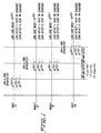
- Figure 1 shows the relation of system time at various points in the CDMA system.
- the system time at various points in the transmission and the reception precesses is the absolute time referenced at the base station antenna offset by the one-way or round-trip delay of the transmission, as appropriate.
- Time measurements are referenced to the transmit and receive antennas of the base station and the radio frequency connector of the mobile station.
- the base stations can be synchronized as described above through a common time Reference; GPS. Therefore, the signals transmitted from the base stations are synchronized in time. However, due to different propagation delays in the links, the signals arrive at different time instants at the mobile station.
- a rake receiver is used to handle time dispersion and the macro-diversity can be seen as time dispersion from the receivers point-of-view. The principle of the rake receiver is to collect the energies from different paths and combine them before a bit-decision is made.
- U.S. Patent No. 5,164,958 discloses a spread spectrum cellular system, i.e., a synchronous CDMA system. This patent identifies cellular cells being large enough to create multi-path signals with delayed differences larger than a chip time interval and discloses the use of a rake type receiver which combines the multi path components. It is cited as but one example of this technology.
- the present invention overcomes the above mentioned problems and achieves synchronization of base stations in the down-link, on a call by call basis, when a mobile station is linked to more than one base station.
- the base stations may or may not be synchronized, but the present invention calls for only a specific connection or communications down-link to be synchronized, the synchronization taking into account the propagation delays of the communication paths.
- the time difference between the connected base station's signal and the macro-diversity candidate base station's signal is measured by a mobile station. This measurement is then transmitted to the network.
- the measurements can be used to achieve synchronization by means of frame staggering.
- the present invention achieves its synchronization between the traffic channels transmitted from different base stations to a mobile station in the following manner.
- the mobile station measures the difference in time delay between reception of a reference channel, e.g., a common control channel (with no frame staggering) from surrounding base stations and a reference base station.
- the channels from different base stations may use the same or different frequencies. These values are sent to a network in a measurement report. If macro-diversity is to be utilized, a new base station will be told of a time offset that should be used for the newly established call (or traffic channel) connection.
- the traffic channel can be arbitrarily offset relative to the control channel and other traffic channels of the individual base station. When data arrives at the base station, it is transmitted according to the specified time offset relative to control channel frames.
- the new signal path will be received by the mobile station within a rake window, thereby avoiding the introduction of unnecessary interference.
- the offset of the traffic channel is updated on a periodic basis.
- the base stations can be unsynchronized because no base station synchronization (as opposed to call link synchronization) is needed for achieving macro-diversity.
- time alignment commands With time alignment commands, synchronized reception in the mobile station can be achieved even for large cells, which is not the case for base station synchronization.
- the need for buffering of the signal before macro-diversity combining is greatly reduced, thereby reducing the complexity of the receiver in the mobile stations.
- the present invention will now be described with reference to one possible embodiment. The description should not be construed as limitive, but merely exemplary. The following definitions for the down-link are used herein.
- the "active set” is the set of base stations transmitting to a mobile station and an "active set update" ASU is when this set is modified.
- a handover from a first base station BS1 to a second base station BS2 means that before the handover, the active set contains only a first base station BS1 and after the handover only base station BS2 in normal situations.
- Macro-diversity is when more than one base station is in the active set. Macro-diversity may involve base stations transmitting on different frequencies or on the same frequency.
- Soft handover between two base stations means that macro-diversity between the two base stations is used during the handover, irrespective of the combining method used.
- Hard handover between two base stations means that macro-diversity between the two base stations is not used during the handover.
- Seamless handover means that the handover is not perceived by the user, and could be hard or soft handovers.
- ⁇ 1 is the propagation delay from a first base station BS1 to a mobile station MS and ⁇ 2 is the propagation delay from a second base station BS2 to the mobile station MS.
- ⁇ 1 is a traffic channel offset relative to a control channel on the first base station BS1 and ⁇ 2 is a traffic channel offset relative to a control channel on the second base station BS2.
- the base stations BS1, BS2 and BS3 are connected by land lines in typical existing systems to a Radio Network Controller RNC. In an actual system, there would be many base stations and a multiplicity of mobile stations. Furthermore, the network could be connected to other networks by land lines.
- Figure 2 has been simplified to better emphasize the present invention.
- a first base station BS1 can establish a communication link with a mobile station MS.
- the first base station BS1, in the active set, can transmit and receive communications from various mobile stations over a plurality of communication channels. These channels are defined by the CDMA method.
- Among the communication channels is a control channel receivable by all mobile stations upon which broadcast overhead messages and the like are transmitted.
- the cellular system is designed for transmission both analog information, e.g., speech in digitized form, and pure digital information.
- the term communication link is used for any form of communication channel between a mobile station and a base station in the same system or another system.
- the mobile station MS When a call is initiated by a mobile station MS, the mobile station MS receives broadcast overhead messages from neighboring base stations, determines which base station has the strongest signal, and determines what channels are available from a base station having the strongest signal from the respective broadcast overhead message. If a communication channel is available, the mobile station MS initiates a communication link with a first base station BS1. Alternatively, a base station can initiate a link with a mobile station MS by broadcasting the mobile stations MS mobile identification number (MIN). Once the communication link is established, it may become desirable for the mobile station MS to be linked to more than one base stations in macro-diversity.
- the first base station BS1 transmits and receives substantially the same information to and from the mobile station MS that a second base station BS2 does. These transmitted signals are not necessarily identical, due to interference and other factors, but are substantially identical.
- Macro-diversity may be used during handoff of a mobile station MS from one base station to another. This occurs when the mobile station approaches a border of a cell wherein the communication link between a first base station BS1 and the mobile station MS becomes tenuous. It therefore becomes desirable to initiate communications with a second base station BS2, preferably through Mobile Assisted Handoff (MAHO) such as disclosed in U.S. Patent No. 5,042,082 to Dahlin.
- MAHO Mobile Assisted Handoff
- the present invention provides seamless, soft handover of a communication link with the mobile station MS by establishing a communication with more than one base station, e.g., both the first and second base stations BS1 and BS2.
- the initial communication link with the first base station BS1 can be dropped.
- Macro-diversity can be used for reasons other than handover, such as in noisy environments.
- the difference in time of the received rays from the base stations can be quite large even if the base stations are synchronized to each other. This will imply that the maximum time span in the rake detection has to be increased not only to handle the time dispersion but also the delays of the signals from different base stations which can be larger, e.g., hundreds of micro seconds.
- the present invention measures the time difference of the macro-diversity candidate base station's BS2 signal and the connected base station's BS1 signal. This measure can be used to achieve synchronization with the means of frame staggering.
- the present invention entails synchronizing the base stations in the down-link, on a call by call basis, when a mobile station is in macro-diversity.
- the base stations may or may not be synchronized, but the present invention relieves the necessity of base station synchronization while accommodating for propagation delay.
- the time difference between a connected base station's BS1 signal and the macro-diversity candidate base station BS2 is measured by a mobile station MS. This measurement is then transmitted back to the network.
- the measurements of the propagation delay can be used to stagger the frames of data thereby synchronizing the two base stations involved in the macro-diversity communications link.
- step S1 a call link is established between a first base station BS1 and a mobile station MS.
- the mobile station MS When in active mode, the mobile station MS continuously measures the signal strength of neighboring base stations BS2, BS3, etc, as shown in step S2.
- the neighboring base stations BS2, BS3, etc. can measure the signal strength of the mobile station MS, however the mobile assisted handoff (MAHO) is generally preferred.
- MAHO mobile assisted handoff
- a call link is initiated with at least one neighboring base station BS2, preferably the base station having the strongest signal strength and an available channel.
- the call link can be initiated with the second base station BS2 forming a communication link with the mobile station MS by broadcasting on the same channel as the call link with the first base station BS1, for instance.
- the first and second base stations BS1 and BS2 can transmit on the same or different frequencies, whichever is advantageous.
- the mobile station MS measures the difference in time delay between the reception of a channel with no frame staggering (e.g., a common control channel) from surrounding base stations and a reference base station. These values are sent to a network in a measurement report.
- a new base station B2 will transmit data in a traffic channel with the time offset that should be used for the newly established traffic channel connection.
- data arrives at the second base station BS2 from the network RNC, it is transmitted according to the specified time offset relative to the control channel frames.
- the new signal path will be received by the mobile station MS within a rake window of a rake receiver such as disclosed in U.S. Patent No. 5,237,586 to Bottomley. This avoids the introduction of unnecessary interference.
- the offset of the traffic channel is updated on a periodic basis.
- one of the call links can be disconnected, which is typically done in a call handoff.
- the radio network controller RNC is assumed to send a data frame to both base stations BS1, BS2 at the same time when macro-diversity is employed.
- the radio network controller-base station delays T 1 and T 2 can be variable from frame to frame.
- the difference in delays is further assumed to be less than T (e.g., a couple of milli-seconds), i.e., T 1 - T 2 ⁇ T
- T 1 - T 2 ⁇ T e.g., a couple of milli-seconds
- the propagation delay difference is bounded as ⁇ 1 - ⁇ 2 ⁇ ⁇ .
- the mobile station MS listens to the first base station BS1 on first traffic channel TCH1.
- the first traffic channel frames starts ⁇ 1 after the first control channel (CCH1) frames at the first base station BS1.
- ⁇ 1 is set by the radio network controller.
- the resulting time to buffer the frames in the first base station BS1 before transmission is then T b1 , and if T 1 is variable, the buffering time T b1 will also be variable.
- the MS measures the time delay T m of the first control channel CCH1 from the second bases station BS2 relative to the first control channel CCH1 of the first base station BS1. T m is reported to the radio network controller RNC.
- the radio controller knows ⁇ 1 at the first base station BS1.
- the ⁇ 2 to be used as offset for the second traffic channel TCH2 relative to the second control channel CCH2 at the second base station BS2 has to be determined by the radio network controller.
- the resulting time to buffer the frames from the radio network controller is T b2 .
- T m T 2 + T b2 - ⁇ 2 + ⁇ 2 - (T1 + T b1 - ⁇ 1 + ⁇ 1 )
- T b2 must be positive, since the second base station BS2 cannot transmit before it has received the frame from the radio network controller. Therefore, it is necessary that T b1 > T + ⁇
- T b2 must be less than T f , since otherwise the second base station BS2 would transmit the data at least one frame too early. Therefore, it is necessary that T b1 ⁇ T f - (T + ⁇ ).
- the first base station BS1 needs to report the first base station buffering delay T b1 to the radio network controller RNC, so that the radio network controller RNC can increase ⁇ 1 if T b1 is too low, and decrease ⁇ 1 if T b1 is too high. Further, the maximum delay difference T on the radio network controller-base station interface between two base stations must satisfy equation (7) above.
- timing advance can be used from the radio network controller RNC to the base stations, thus minimizing the resulting T.
- ⁇ 1 and ⁇ 2 will change slowly. Based on mobile station MS reports of T m , the radio network controller can update ⁇ 1 and ⁇ 2 continuously to maintain the synchronization of the signals at the mobile station MS.
- the detector time span and the delay spread of the channel will determine how often it is necessary to update the traffic channel offset values.
- T b1 or T b2 must be monitored. If necessary, ⁇ 1 and ⁇ 2 has to be increased/decreased by the same amount.
- T specifies the maximum delay difference between all base stations in the area where the mobile station MS moves. Then, it is not necessary that equations (5) and (6) are satisfied for T b2 at the second base station BS2.
- the base station When the traffic channel offset ⁇ is increased, the base station must include a number of dummy chips between two transmitted symbols. If ⁇ is decreased, a number of chips has to be removed from one symbol before transmission. Thus, there is a need for a chip buffer at the transmitter. The mobile station's correlator will then find the displaced correlation peak, but the probability of symbol error will be increased for the symbol of displacement. The change of ⁇ should not exceed the search window size in the mobile station correlator.
- Figure 5 summarizes what measurements and parameters are communicated in the system to maintain synchronization of the signals at the mobile station MS.
- one base station BS1, BS2 or BS3 is defined as reference base station to measure of T m in the mobile station MS. Together with pilot strength measurements of transmitting and neighboring base stations, a control channel offset T m relative the control channel CCH of the reference base station shall be reported. This means that it is not enough to correlate with the pilot codeword.
- radio network controller-base station delay difference cannot be bounded (which may be the case with packet switched radio network controller-base station interface), there are cases where the two frames that should arrive in the mobile station MS actually arrive with an offset of one frame.
- the latter requires that the base station must be re-synchronized whenever a base station is taken into operation, e.g., a new base station, a repaired base station etc.
- the present invention allows synchronization per mobile station for soft handover on one radio frequency, under certain circumstances.
- the radio network controller-base station delay difference must be bounded to less than half of the CDMA frame duration (a couple of milliseconds).
- a reference base station is identified.
- the mobile station MS needs to measure the control channel offset of all measured base stations relative the reference base station.
- the base stations need to report to the radio network controller RNC the buffering time before transmission in the base stations.
- the rake detector time span need not be dimensioned for propagation delays. Even if the rake detector time span can be made large easily, the constraint on delay difference on the radio network controller-base station interface still has to be considered.
- FIG. 6 illustrates in block diagrammatic form the pertinent parts of the mobile station MS.
- the mobile station MS includes a receiver 60 connected to a pair of demodulators 61A and 61B for demodulating the signal received on a first channel CCH 1 and a second channel CCH 2, respectively.
- the demodulated signal is then fed to a pair of receivers 62A and 62B for receiving first channel and the second channel demodulated signals, respectively.
- the signals are fed to a delay measurement unit 63.
- the delay measurement unit measures the delay in accordance within equations above to produce a control channel offset T m .
- the control channel offset is then fed to a control channel generator 64 which generates the signal for transmission on the control channel.
- This signal is then fed to a spreader 65 which spreads the signal in accordance with a DS-CDMA technique.
- the spread signal is then fed to a pulse shaping circuit 66 for transmission by a transmitter 67.
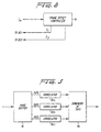
- FIG. 7 shows the pertinent part of a base station.
- the circuitry includes a receiver 70 connected to a demodulator 71 which receives, e.g., control channel signals from mobile stations MS.
- the demodulated signal is then fed to a channel receiver 72, the output of which is the control channel offset TM from a mobile station MS.
- a traffic channel generator 73 receives information and outputs a signal to a spreader 74.
- the spreader 74 superimposes a higher rate code on the information signal from the traffic channel 73 in accordance with DS-CDMA technique.
- the coded signal is delayed by the traffic channel offset ⁇ 1 , in the spreader 74 according to the above equations.
- the delayed signal is then sent to a pulse shaper 75 and transmitted by a transmitter 76 in a conventional fashion.
- FIG 8 shows the pertinent parts of a radio network control RNC.
- the radio network control receives a measured offset T m from the mobile stations MS of a second control channel CCH2 from a second base station BS2 relative to a first control channel CCH1 from a first base station BS1.
- This measured offset is input to a frame offset controller 81 which generates the traffic channel offsets ⁇ 1 and ⁇ 2 , which were then conveyed to the first base station BS1 and the second base station BS2, respectively.
- Figure 9 shows part of a control channel receiver including a rake receiver which includes a rake buffer 91.
- the outputs from the rake buffer 91 are given corresponding, different time shifts relative to the input signal.
- the outputs are connected to three correlators 92a, 92b, and 92c.
- Outputs of the correlators 92a, 92b, and 92c are connected to a combining unit 93 for combining the output, and the correlated signal is output for further processing.
- a communication link from a base station may be transmitted in a compressed mode wherein a frame of data includes an information part and an idle part. This allows the mobile stations to measure at least one neighboring base station during an idle time slot in the compressed mode.
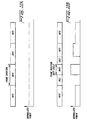
- discontinuous transmission is used with the CDMA method. This is achieved by using a lower spreading ratio, whereby the spread information only fills an information part of a frame in the compressed mode, leaving a residual, idle part idle in which no power is transmitted, as shown in Figure 10B.
- the slotted code division multiple access communication technique impresses an informational data stream to be transmitted upon a higher rate data stream to produce a signature sequence
- the signature sequence is transmitted on a channel according to a frame structure comprising frames, each frame being of a specific time duration.
- the signature sequence is intermittently transmitted in the compressed mode wherein the frame includes an information part containing the signature sequence and an idle part wherein the signature sequence is not transmitted.
- the duty cycle between the information part of the frame and the frame duration is controlled on a frame by frame basis.
- the compressed mode includes more than one compressed mode frame structure, each different compressed mode structure having a different duty cycle.
- the power used on the information part of the frame is a function of the duty cycle in a preferred embodiment of the present invention. Increased power is needed to maintain transmission quality if the duty cycle is reduced. During the rest of the frame, i.e., the idle part, the power is turned off.
- the mobile station MS is in macro-diversity mode, it is necessary that all connected base stations BS1, BS2, BS3, etc. employ the same transmission mode for any given frame.
- This synchronization can be achieved in any suitable fashion, and in a preferred embodiment is achieved through the network RNC connecting the base stations BS1 and BS2 as described above.
- the evaluation of other carrier frequencies for basing handover decisions is easily preformed by using the compressed mode in the down-link from a base station to a mobile station on a deterministic basis.
- the evaluation of the other carrier frequencies can be carried out in any suitable fashion, such as disclosed in U.S. Patent No. 5,175,867 to Wejke et al.
- Either the base station or the mobile station can perform the evaluation in the up-link or the down-link, and in the preferred embodiment the mobile station MS performs the evaluation.
- the mobile station MS performs measurements on other carrier frequencies during the idle part of the compressed mode frame since during this time it is not required to listen to the base station to which it is currently linked.
- the measurements are relayed to the network RNC (through the currently linked base station or base stations), providing the means for a mobile assisted handover (MAHO).
- MAHO mobile assisted handover
- the compressed mode is used only intermittently at a rate determined by the network RNC.
- the network RNC determines the frequency of use of the compressed mode based on a variety of factors, such as the relative broadcast conditions as affected by weather and other interfering factors, and the relative call density. Most frames still use normal mode transmission in typical situations.
- the variation in total transmitted power from a base station can be smoothed by staggering (spreading in time) the deployment of compressed mode over a number of users in a certain time span. Since signal strength measurement on another carrier frequency is likely to require only a fraction of a frame, the duty cycle can be made high, thereby reducing the variation in the power transmission.
- Execution of a call handover is handled in the compressed mode in a preferred embodiment of the present invention.
- the compressed mode is entered. Communication with the old base station BS1 is maintained while establishing a new link during the idle part of the frame. Thereby complete synchronization with the new base station BS2 is obtained, establishing a new link.
- the handover is completed by dropping the old link and returning to normal mode transmission.
- communication to all base stations simultaneously can be employed (establishing macro-diversity on one or more carrier frequencies). This scheme for seamless inter-frequency handover can be used for both up- and down-links.
- the duty cycle can be varied according to the requirements for obtaining synchronization. However, if simultaneous communication (macro-diversity) is used, a duty cycle of about 50% is preferred.
- the present invention's use of normal and compressed mode frames provides the ability to exploit the advantages of slotted transmission/reception in hierarchical cell structures while using DS-CDMA. It is possible to measure other carrier frequencies, thereby providing reliable handover decisions. Further, handover execution between carrier frequencies can be made seamless by establishing a new link before releasing the old one. This can be done without the need for two receivers. There are other reasons other than call handover for using macro-diversity, such as maintaining a high quality communication link with a mobile station when the mobile station is traveling in an area that has high radio interference.
- the first base station BS1 is the base station of a microcell
- the second base station BS2 is a macrocell or an umbrella cell encompassing the coverage area of the microcell.
- various obstacles such as buildings can interfere with the signal originating from the first base station BS1. Therefore, a redundant signal is transmitted from the macrocell BS2 to assure clear communication quality.
- the primary purpose of macro-diversity is call handover.
Description
- The present invention relates to the use of Code Division Multiple Access (CDMA) communications techniques in cellular radio telephone communication systems, and more particularly, to a method using a Direct Sequence-Code Division Multiple Access (DS-CDMA) communication technique for aligning transmissions in macro-diversity down-links from more than one base station to the same mobile station.
- CDMA or spread spectrum communications have been in existence since the days of World War II. Early applications were predominantly military oriented. However, today there has been an increasing interest in using spread spectrum systems in commercial applications. Some examples include digital cellular radio, land mobile radio, and indoor and outdoor personal communication networks, generically referred to as cellular systems herein.
- Currently, channel access in cellular systems is achieved using Frequency Division Multiple Access (FDMA) and Time Division Multiple Access (TDMA) methods. In FDMA, a communication channel is a single radio frequency band into which a signal's transmission power is concentrated. Interference with adjacent channels is limited by the use of band pass filters which only pass signal energy within the specified frequency band. Thus, with each channel being assigned a different frequency, system capacity is limited by the available frequencies as well as by limitations imposed by channel reuse.
- In TDMA systems, a channel consists of a time slot in a periodic train of time intervals over the same frequency. Each period of time slots is called a frame. A given signal's energy is confined to one of these time slots. Adjacent channel interference is limited by the use of a time gate or other synchronization element that only passes signal energy received at the proper time. Thus, the problem of interference from different relative signal strength levels is reduced. With FDMA or TDMA systems or hybrid FDMA/TDMA systems, the goal is to insure that two potentially interfering signals do not occupy the same frequency at the same time.
- Capacity in a TDMA system is increased by compressing the transmission signal into a shorter time slot. As a result, the information must be transmitted at a correspondingly faster burst rate which increases the amount of occupied spectrum proportionally.
- In present systems, such as GSM (Global System for Mobile Communication) , time-alignment of mobile stations in an up-link is used to ensure that a base station receives the signal from a mobile station in the assigned TDMA time-slot. An overlap into a neighboring time-slot, caused by different propagation delays for example, would cause interference with another mobile-to-base station link.
- In contrast to FDMA and TDMA, Code Division Multiple Access (CDMA) allows signals to overlap in both time and frequency. CDMA signals share the same frequency spectrum in present day systems. In the frequency or the time domain, the multiple access signals appear to be on top of each other.
- European Patent Application 0 522 772 discloses a wireless access telephone-to-telephone network interface structure for CDMA cellular radio telephone systems and is cited as but one example of a CDMA system.
- In principle, in a CDMA system the informational data stream to be transmitted is impressed upon a much higher rate data stream known as a signature sequence. Typically, the signature sequence data are binary, providing a bit stream. One way to generate this signature sequence is with a pseudo-noise (PN) process that appears random, but can be replicated by an authorized receiver. The informational data stream and the high bit rate signature sequence stream are combined by multiplying the two bit streams together, assuming the binary values of the two bit streams are represented by +1 or -1. This combination of the higher bit rate signal with the lower bit rate data stream is called coding or spreading the informational data stream signal. Each informational data stream or channel is allocated a unique spreading code.
- A plurality of coded information signals modulate a radio frequency carrier, for example by quadrature phase shift keying (QPSK), and are jointly received as a composite signal at a receiver. Each of the coded signals overlaps all of the other coded signals, as well as noise-related signals, in both frequency and time. If the receiver is authorized, then the composite signal is correlated with one of the unique codes, and the corresponding information signal can be isolated and decoded.
- One CDMA technique, called "traditional CDMA with direct spreading", uses a signature sequence to represent one bit of information. Receiving the transmitted sequence or its complement (the transmitted binary sequence values) indicates whether the information bit is a "0" or "1". The signature sequence usually comprises N bits, and each bit is called a "chip". The entire N-chip sequence, or its complement, is referred to as a transmitted symbol. The receiver correlates the received signal with the known signature sequence of its own signature sequence generator to produce a normalized value ranging from -1 to +1. When a large positive correlation results, a "0" is detected; when a large negative correlation results, a "1" is detected.
- Another CDMA technique, called "enhanced CDMA with direct spreading" allows each transmitted sequence to represent more than one bit of information. A set of code words, typically orthogonal code words or bi-orthogonal code words, is used to code a group of information bits into a much longer code sequence or code symbol. A signature sequence or scramble mask is modulo-2 added to the binary code sequence before transmission. At the receiver, the known scramble mask is used to descramble the received signal, which is then correlated to all possible code words. The code word with the largest correlation value indicates which code word was most likely sent, indicating which information bits were most likely sent. One common orthogonal code is the Walsh-Hadamard (WH) code.
- In both traditional and enhanced CDMA, generically referred to as Direct Sequence-Code Division Multiple Access (DS-CDMA), the "information bits" referred to above can also be coded bits, where the code used is a block or convolutional code. One or more information bits can form a data symbol. Also, the signature sequence or scramble mask can be much longer than a single code sequence, in which case a subsequence of the signature sequence or scramble mask is added to the code sequence.
- In a conventional cellular communication systems such as AMPS, reliable handover between base stations is viable if the carrier frequency is not changed. Handoff procedure for handing a call link from one cell to another is initiated when the cell site receiver handling the call detects that the received signal strength from a mobile station falls below a predetermined threshold value. A low signal strength indication implies that the mobile station is near a cell border. When the signal level falls below a threshold, the base station queries the system controller to determine whether a neighboring base station receives the mobile telephone signal with better signal strength than the current base station.
- The system controller in response to the base station inquiry sends messages to the neighboring base stations for the handoff requests. The neighboring base stations employ scanning receivers which look for the signal of the base station on a specified channel. Should one of the neighboring base stations report an adequate signal level to the system controller, then a handoff is attempted.
- A handoff is initiated when an idle channel from the new base station is selected. A control message is sent to the mobile station commanding it to switch from the current channel to a new channel. At the same time, the system controller switches the call link from the first base station to the second base station. In some systems, such as disclosed in U.S. Patent No. 5,101,501, the call link from the first base station is maintained for a period after initiating and establishing a call link to the second base station. This process is called soft handover through macro-diversity and reduces the perception of the handover due to loss of data during the actual handover. Macro-diversity may be implemented for reasons other than handover, e.g., in noisy environments to assure good signal quality.
- In a CDMA system overlap of time-slots as in TDMA systems is not a problem since a mobile station transmits continuously, and thus does not need to synchronize to other mobile stations. However, when a mobile station is connected to more than one base station in macro-diversity, there is a need to synchronize the base stations in the down-link (also know as the forward link).
- Macro-diversity in a CDMA system can be achieved with synchronized base stations. The base stations can be synchronized with all base station digital transmissions being referenced to a common CDMA system-wide time scale that uses the Global Positioning System (GPS) time scale, which is traceable to and synchronous with Universal Coordinated Time (UTC). The signals from all the base stations are transmitted at the same instant.
- European Patent Application 0 335 846 relates to a cellular digital mobile radio system with plural base station transmitters within a single cell. The same message information is digitally modulated by the different base station transmitters within a single cell to a given mobile station with a mutual transmission time shift. The transmission time shift is selected individually for each mobile station such that the corresponding digitally modulated radio signals with the same message information to a given station from different base station transmitters arrives practically simultaneously at the mobile station. This system does not involve the establishment of two separate call links between base stations. As such, it does not involve a network controller in its method or the use of common control channels in establishing the delay in arrival of the signals from the base stations to the mobile stations.
- Figure 1 shows the relation of system time at various points in the CDMA system. The system time at various points in the transmission and the reception precesses is the absolute time referenced at the base station antenna offset by the one-way or round-trip delay of the transmission, as appropriate. Time measurements are referenced to the transmit and receive antennas of the base station and the radio frequency connector of the mobile station.
- In order to enable macro-diversity, the base stations can be synchronized as described above through a common time Reference; GPS. Therefore, the signals transmitted from the base stations are synchronized in time. However, due to different propagation delays in the links, the signals arrive at different time instants at the mobile station. Normally in CDMA systems a rake receiver is used to handle time dispersion and the macro-diversity can be seen as time dispersion from the receivers point-of-view. The principle of the rake receiver is to collect the energies from different paths and combine them before a bit-decision is made.
- U.S. Patent No. 5,164,958 discloses a spread spectrum cellular system, i.e., a synchronous CDMA system. This patent identifies cellular cells being large enough to create multi-path signals with delayed differences larger than a chip time interval and discloses the use of a rake type receiver which combines the multi path components. It is cited as but one example of this technology.
- In unregulated environments (where the spectrum use between operators is not regulated) , it is difficult to have the base stations synchronized between different operators. Also, a system that relies on a common time-Reference in order to function properly will be sensitive to failures of the time Reference system.
- In cells with large radii, the differences in propagation delays between the base stations will become large. This would increase the complexity of the receiver in a mobile station, due to the received signal needing to be buffered for at least the time difference between the arrival of the first path from the base station with the lowest delay, and the last path from the base station with the longest delay. The span in which the signals can arrive and be properly received is called the rake window. If the signals do not fit into the rake window they will only cause additional interference. The use of time alignment commands to synchronize TDMA bursts in GSM is described in GSM 05.10.
- The present invention overcomes the above mentioned problems and achieves synchronization of base stations in the down-link, on a call by call basis, when a mobile station is linked to more than one base station. The base stations may or may not be synchronized, but the present invention calls for only a specific connection or communications down-link to be synchronized, the synchronization taking into account the propagation delays of the communication paths.
- In order to synchronize the signals for a specific connection, the time difference between the connected base station's signal and the macro-diversity candidate base station's signal is measured by a mobile station. This measurement is then transmitted to the network. The measurements can be used to achieve synchronization by means of frame staggering.
- More specifically, the present invention achieves its synchronization between the traffic channels transmitted from different base stations to a mobile station in the following manner. The mobile station measures the difference in time delay between reception of a reference channel, e.g., a common control channel (with no frame staggering) from surrounding base stations and a reference base station. The channels from different base stations may use the same or different frequencies. These values are sent to a network in a measurement report. If macro-diversity is to be utilized, a new base station will be told of a time offset that should be used for the newly established call (or traffic channel) connection. The traffic channel can be arbitrarily offset relative to the control channel and other traffic channels of the individual base station. When data arrives at the base station, it is transmitted according to the specified time offset relative to control channel frames. The new signal path will be received by the mobile station within a rake window, thereby avoiding the introduction of unnecessary interference. When the mobile station moves away from the original base station with which it had a call link toward the new base station, the offset of the traffic channel is updated on a periodic basis.
- Among the advantages of the present invention are that the base stations can be unsynchronized because no base station synchronization (as opposed to call link synchronization) is needed for achieving macro-diversity. With time alignment commands, synchronized reception in the mobile station can be achieved even for large cells, which is not the case for base station synchronization. Also, the need for buffering of the signal before macro-diversity combining is greatly reduced, thereby reducing the complexity of the receiver in the mobile stations.
- The present invention will now be described with reference to the accompanying drawing figures in which:
- Figure 1 shows the relation of a system time at various points in a CDMA system;
- Figure 2 illustrates communication paths in a cellular system;
- Figure 3 shows various time delays and offsets in a cellular system in accordance with the present invention;
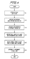
- Figure 4 is a flowchart in accordance with the present invention;
- Figure 5 illustrates the logical links for maintaining synchronization the mobile station MS;
- Figure 6 is a block diagram of the relevant portion of the mobile station in accordance with the present invention;
- Figure 7 is a block diagram of the relevant portion of the base station in accordance with the present invention;
- Figure 8 is a block diagram of the relevant portion of the radio network controller in accordance with the present invention;
- Figure 9 is a block diagram of part of a control channel receiver including a rake receiver and correlators; and
- Figures 10A and 10B illustrate normal and compressed modes of DS-CDMA transmission.
-
- The present invention will now be described with reference to one possible embodiment. The description should not be construed as limitive, but merely exemplary.
The following definitions for the down-link are used herein. The "active set" is the set of base stations transmitting to a mobile station and an "active set update" ASU is when this set is modified. A handover from a first base station BS1 to a second base station BS2 means that before the handover, the active set contains only a first base station BS1 and after the handover only base station BS2 in normal situations. Macro-diversity is when more than one base station is in the active set. Macro-diversity may involve base stations transmitting on different frequencies or on the same frequency. Soft handover between two base stations means that macro-diversity between the two base stations is used during the handover, irrespective of the combining method used. Hard handover between two base stations means that macro-diversity between the two base stations is not used during the handover. Seamless handover means that the handover is not perceived by the user, and could be hard or soft handovers. - An overview of signal paths in a cellular system is shown in Figure 2 wherein τ1 is the propagation delay from a first base station BS1 to a mobile station MS and τ2 is the propagation delay from a second base station BS2 to the mobile station MS. λ1 is a traffic channel offset relative to a control channel on the first base station BS1 and λ2 is a traffic channel offset relative to a control channel on the second base station BS2. The base stations BS1, BS2 and BS3 are connected by land lines in typical existing systems to a Radio Network Controller RNC. In an actual system, there would be many base stations and a multiplicity of mobile stations. Furthermore, the network could be connected to other networks by land lines. Figure 2 has been simplified to better emphasize the present invention.
- In the cellular system, a first base station BS1 can establish a communication link with a mobile station MS. The first base station BS1, in the active set, can transmit and receive communications from various mobile stations over a plurality of communication channels. These channels are defined by the CDMA method. Among the communication channels is a control channel receivable by all mobile stations upon which broadcast overhead messages and the like are transmitted. The cellular system is designed for transmission both analog information, e.g., speech in digitized form, and pure digital information. For purposes of this application, the term communication link is used for any form of communication channel between a mobile station and a base station in the same system or another system.
- When a call is initiated by a mobile station MS, the mobile station MS receives broadcast overhead messages from neighboring base stations, determines which base station has the strongest signal, and determines what channels are available from a base station having the strongest signal from the respective broadcast overhead message. If a communication channel is available, the mobile station MS initiates a communication link with a first base station BS1. Alternatively, a base station can initiate a link with a mobile station MS by broadcasting the mobile stations MS mobile identification number (MIN). Once the communication link is established, it may become desirable for the mobile station MS to be linked to more than one base stations in macro-diversity. The first base station BS1 transmits and receives substantially the same information to and from the mobile station MS that a second base station BS2 does. These transmitted signals are not necessarily identical, due to interference and other factors, but are substantially identical.
- Macro-diversity may be used during handoff of a mobile station MS from one base station to another. This occurs when the mobile station approaches a border of a cell wherein the communication link between a first base station BS1 and the mobile station MS becomes tenuous. It therefore becomes desirable to initiate communications with a second base station BS2, preferably through Mobile Assisted Handoff (MAHO) such as disclosed in U.S. Patent No. 5,042,082 to Dahlin. However, unlike conventional systems, the present invention provides seamless, soft handover of a communication link with the mobile station MS by establishing a communication with more than one base station, e.g., both the first and second base stations BS1 and BS2.
- Once the mobile station has established communications with a second base station BS2, the initial communication link with the first base station BS1 can be dropped. Macro-diversity can be used for reasons other than handover, such as in noisy environments.
- The difference in time of the received rays from the base stations can be quite large even if the base stations are synchronized to each other. This will imply that the maximum time span in the rake detection has to be increased not only to handle the time dispersion but also the delays of the signals from different base stations which can be larger, e.g., hundreds of micro seconds. In order to not employ macro-diversity when it cannot be utilized in the mobile station MS, the present invention measures the time difference of the macro-diversity candidate base station's BS2 signal and the connected base station's BS1 signal. This measure can be used to achieve synchronization with the means of frame staggering.
- Because only one signal originates from the mobile station MS, and two signals originate from the base stations (one from the first base station BS1 and one from the second base station BS2), synchronization is only in the down-link. Macro-diversity in the up-link is not done in the rake receiver in the preferred embodiment, because signals from different base stations are combined in a radio network controller RNC. Thus, the present invention entails synchronizing the base stations in the down-link, on a call by call basis, when a mobile station is in macro-diversity. The base stations may or may not be synchronized, but the present invention relieves the necessity of base station synchronization while accommodating for propagation delay.
- In order to synchronize the signals of a specific connection, the time difference between a connected base station's BS1 signal and the macro-diversity candidate base station BS2 is measured by a mobile station MS. This measurement is then transmitted back to the network. The measurements of the propagation delay can be used to stagger the frames of data thereby synchronizing the two base stations involved in the macro-diversity communications link.
- The basic procedure is:
- 1. The MS mobile station measures the difference in time between the reception of a Control Channel (CCH) from the surrounding base stations and one reference base station (CDMA frame offset) . CCH is a common control channel that is always broadcast by a base station.
- 2. These values are sent to the Radio Network Controller (RNC) in an ordinary measurement report.
- 3. If the network RNC decides that macro-diversity should be utilized, a new base station BS2 will then be told the time offset that should be used for this traffic channel connection. The traffic channel can be arbitrarily offset relative the CCH and other traffic channels of the new base station BS2.
- 4. When data arrives from the network RNC, the base station BS shall transmit it on the next traffic channel frame. Thus the data is buffered, resulting in a buffering delay.
- 5. The new signal path will be received in the mobile station MS at about the same time instant as the old signal.
- 6. When the mobile station MS moves from the first base station BS1 towards the new base station BS2, the offset of the traffic channels is updated.
-
- This procedure is illustrated in the flowchart of Figure 4. In step S1, a call link is established between a first base station BS1 and a mobile station MS. When in active mode, the mobile station MS continuously measures the signal strength of neighboring base stations BS2, BS3, etc, as shown in step S2. Alternatively, the neighboring base stations BS2, BS3, etc., can measure the signal strength of the mobile station MS, however the mobile assisted handoff (MAHO) is generally preferred. These measurements are then transmitted through the base stations in the active set, here first base station BS1, to the radio network controller in step S3.
- Thereafter, as shown in step S4, a call link is initiated with at least one neighboring base station BS2, preferably the base station having the strongest signal strength and an available channel. The call link can be initiated with the second base station BS2 forming a communication link with the mobile station MS by broadcasting on the same channel as the call link with the first base station BS1, for instance. The first and second base stations BS1 and BS2 can transmit on the same or different frequencies, whichever is advantageous. As shown in step S5, the mobile station MS measures the difference in time delay between the reception of a channel with no frame staggering (e.g., a common control channel) from surrounding base stations and a reference base station. These values are sent to a network in a measurement report. If macro-diversity is to be utilized, a new base station B2 will transmit data in a traffic channel with the time offset that should be used for the newly established traffic channel connection. When data arrives at the second base station BS2 from the network RNC, it is transmitted according to the specified time offset relative to the control channel frames. The new signal path will be received by the mobile station MS within a rake window of a rake receiver such as disclosed in U.S. Patent No. 5,237,586 to Bottomley. This avoids the introduction of unnecessary interference.
- When the mobile station MS moves away from the original base station BS1 with which it has had a call link and toward the new base station BS2, the offset of the traffic channel is updated on a periodic basis. At step S6, one of the call links (either from the first base station BS1 or the second base station BS2) can be disconnected, which is typically done in a call handoff.
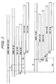
- To explain the set-up procedure of macro-diversity synchronization in detail, the following notations are used with reference to Figures 2 and 3:
- Tf =
- Duration of one frame, e.g. 10 ms,
- T1 =
- Transmission delay from radio network controller to the first base station BS1,
- T2 =
- Transmission delay from radio network controller to the second base station BS2,
- γ =
- Maximum radio network controller-base station delay difference for two base stations,
- τ1 =
- Propagation delay from the first base station BS1 to the mobile station MS,
- τ2 =
- Propagation delay from the second base station BS2 to the mobile station MS,
- τ =
- Maximum base station-mobile station delay difference for two base stations,
- λ1 =
- Traffic channel offset relative to a control channel CCH on the first base station BS1,
- λ2 =
- Traffic channel offset relative to a control channel CCH on the second base station BS2,
- Tb1 =
- Buffering delay in first base station BS1,
- Tb2 =
- Buffering delay in the second base station BS2,
- Tm =
- Measured offset in the mobile MS of the control channel CCH from the second base station BS2 relative to the control channel CCH from the first base station BS1.
- The radio network controller RNC is assumed to send a data frame to both base stations BS1, BS2 at the same time when macro-diversity is employed. The radio network controller-base station delays T1 and T2 can be variable from frame to frame. The difference in delays is further assumed to be less than T (e.g., a couple of milli-seconds), i.e.,
- It is also assumed that the mobile station MS listens to the first base station BS1 on first traffic channel TCH1. The first traffic channel frames starts λ1 after the first control channel (CCH1) frames at the first base station BS1. λ1 is set by the radio network controller. The resulting time to buffer the frames in the first base station BS1 before transmission is then Tb1, and if T1 is variable, the buffering time Tb1 will also be variable.
- When the second base station BS2 is found to be strong enough for macro-diversity, the MS measures the time delay Tm of the first control channel CCH1 from the second bases station BS2 relative to the first control channel CCH1 of the first base station BS1. Tm is reported to the radio network controller RNC.
- The radio controller knows λ1 at the first base station BS1. The λ2 to be used as offset for the second traffic channel TCH2 relative to the second control channel CCH2 at the second base station BS2 has to be determined by the radio network controller.
- When the second base station BS2 uses the λ2 value, the resulting time to buffer the frames from the radio network controller is Tb2.
- The radio network controller determine what λ2 to use as follows. The time from a frame that leaves the radio network controller until it is beginning to be received at the mobile station MS must be equal for the two paths:
- The reported time delay between the control channels CCH1 and CCH2 is:
- These two equations yield
- With the second traffic channel offset λ2 from above and from equation (1), the resulting buffering time in the second base station BS2 is
- Tb2 must be positive, since the second base station BS2 cannot transmit before it has received the frame from the radio network controller. Therefore, it is necessary that
- Further, Tb2 must be less than Tf, since otherwise the second base station BS2 would transmit the data at least one frame too early. Therefore, it is necessary that
- These conditions (5) and (6) can only be satisfied if
- Thus, the first base station BS1 needs to report the first base station buffering delay Tb1 to the radio network controller RNC, so that the radio network controller RNC can increase λ1 if Tb1 is too low, and decrease λ1 if Tb1 is too high. Further, the maximum delay difference T on the radio network controller-base station interface between two base stations must satisfy equation (7) above.
- If T1 and T2 can be estimated, then timing advance can be used from the radio network controller RNC to the base stations, thus minimizing the resulting T.
- When the mobile station MS is moving, τ1 and τ2 will change slowly. Based on mobile station MS reports of Tm, the radio network controller can update λ1 and λ2 continuously to maintain the synchronization of the signals at the mobile station MS. The detector time span and the delay spread of the channel will determine how often it is necessary to update the traffic channel offset values.
- If a new (third) base station BS3 starts transmitting to the mobile station MS, it is necessary that equations (5) and (6) above are satisfied for at least one of the first and second base station BS1 and BS2 (exchanging Tb1 for Tb2). Thus, Tb1 or Tb2 must be monitored. If necessary, λ1 and λ2 has to be increased/decreased by the same amount. When the first base station BS1 stops transmitting, and only the second base station BS2 remains, there are two options. Either, T specifies the maximum delay difference between all base stations in the area where the mobile station MS moves. Then, it is not necessary that equations (5) and (6) are satisfied for Tb2 at the second base station BS2. It is enough with one base station once doing so, which will guarantee that O < Tb < Tf for all other base stations. On the other hand, if T only applies to base stations that can be in macro-diversity together, then λ2 must be adjusted so that equations (5) and (6) are satisfied for the second base station BS2 (Tb2) when the first base station BS1 is disconnected.
- When the traffic channel offset λ is increased, the base station must include a number of dummy chips between two transmitted symbols. If λ is decreased, a number of chips has to be removed from one symbol before transmission. Thus, there is a need for a chip buffer at the transmitter. The mobile station's correlator will then find the displaced correlation peak, but the probability of symbol error will be increased for the symbol of displacement. The change of λ should not exceed the search window size in the mobile station correlator.
- Figure 5 summarizes what measurements and parameters are communicated in the system to maintain synchronization of the signals at the mobile station MS.
- Among the base stations transmitting to the mobile station MS, one base station BS1, BS2 or BS3 is defined as reference base station to measure of Tm in the mobile station MS. Together with pilot strength measurements of transmitting and neighboring base stations, a control channel offset Tm relative the control channel CCH of the reference base station shall be reported. This means that it is not enough to correlate with the pilot codeword.
- Above, it was assumed that the radio network controller-base station delay difference (T1 - T2) can be bounded with T.
- If the radio network controller-base station delay difference cannot be bounded (which may be the case with packet switched radio network controller-base station interface), there are cases where the two frames that should arrive in the mobile station MS actually arrive with an offset of one frame.
- If the delay can be increased to the delay of the most delayed frame, two possible solutions are foreseen:
- (1) The frames on the control channel CCH are numbered and the delay measurement are accompanied with the numbers (the relative offset may suffice); and
- (2) An initial synchronization is performed by sending out a start frame synchronously from the radio network controller and, at reception in the base stations, the control channels CCHs begin directly afterwards.
-
- The latter requires that the base station must be re-synchronized whenever a base station is taken into operation, e.g., a new base station, a repaired base station etc.
- It may be desirable to control the signals from the different base stations to arrive with a controlled delay at the mobile station MS. (This would be the case if the same codewords are used at both base stations. The delay must be larger than the delay spread, to allow identification of each base station.) The same technique as described above can be used.
- If the rake detector can have a large time span, in the order of milliseconds, it can be argued that synchronization of signals at the MS is not an important issue. It seems, however, as if equations (5) and (6) need to be satisfied with an additional term representing the time difference of the signals when arriving at the MS. Thus, equations (7) still needs to be satisfied.
- The present invention allows synchronization per mobile station for soft handover on one radio frequency, under certain circumstances. The radio network controller-base station delay difference must be bounded to less than half of the CDMA frame duration (a couple of milliseconds). For each mobile station a reference base station is identified. The mobile station MS needs to measure the control channel offset of all measured base stations relative the reference base station. The base stations need to report to the radio network controller RNC the buffering time before transmission in the base stations. Then, with use of the timing advance (traffic channel offset) method, the rake detector time span need not be dimensioned for propagation delays. Even if the rake detector time span can be made large easily, the constraint on delay difference on the radio network controller-base station interface still has to be considered.
- Figure 6 illustrates in block diagrammatic form the pertinent parts of the mobile station MS. The mobile station MS includes a receiver 60 connected to a pair of demodulators 61A and 61B for demodulating the signal received on a first channel CCH 1 and a second channel CCH 2, respectively. The demodulated signal is then fed to a pair of receivers 62A and 62B for receiving first channel and the second channel demodulated signals, respectively. After the pair of receivers 62A and 62B, the signals are fed to a delay measurement unit 63. The delay measurement unit measures the delay in accordance within equations above to produce a control channel offset Tm. The control channel offset is then fed to a control channel generator 64 which generates the signal for transmission on the control channel. This signal is then fed to a spreader 65 which spreads the signal in accordance with a DS-CDMA technique. The spread signal is then fed to a pulse shaping circuit 66 for transmission by a transmitter 67.
- Figure 7 shows the pertinent part of a base station. The circuitry includes a receiver 70 connected to a demodulator 71 which receives, e.g., control channel signals from mobile stations MS. The demodulated signal is then fed to a channel receiver 72, the output of which is the control channel offset TM from a mobile station MS.
- On the transmit side of the base station BS, a traffic channel generator 73 receives information and outputs a signal to a spreader 74. The spreader 74 superimposes a higher rate code on the information signal from the traffic channel 73 in accordance with DS-CDMA technique. However, the coded signal is delayed by the traffic channel offset λ1, in the spreader 74 according to the above equations. The delayed signal is then sent to a pulse shaper 75 and transmitted by a transmitter 76 in a conventional fashion.
- Figure 8 shows the pertinent parts of a radio network control RNC. The radio network control receives a measured offset Tm from the mobile stations MS of a second control channel CCH2 from a second base station BS2 relative to a first control channel CCH1 from a first base station BS1. This measured offset is input to a frame offset controller 81 which generates the traffic channel offsets λ1 and λ2, which were then conveyed to the first base station BS1 and the second base station BS2, respectively.
- Figure 9 shows part of a control channel receiver including a rake receiver which includes a rake buffer 91. The outputs from the rake buffer 91 are given corresponding, different time shifts relative to the input signal. The outputs are connected to three correlators 92a, 92b, and 92c. Outputs of the correlators 92a, 92b, and 92c are connected to a combining unit 93 for combining the output, and the correlated signal is output for further processing.
- As an optional feature, a communication link from a base station may be transmitted in a compressed mode wherein a frame of data includes an information part and an idle part. This allows the mobile stations to measure at least one neighboring base station during an idle time slot in the compressed mode.
- Normally in CDMA systems information is transmitted in a structure of frames with fixed length, e.g., 5-20 ms. Information to be transmitted within a frame is coded and spread together. The maximum allowable spreading ratio is conventionally used resulting in continuous transmission during the whole frame, such as shown in Figure 10A. Full frame transmission is denoted the normal mode transmission herein.
- For reliable handover evaluation and execution, discontinuous transmission is used with the CDMA method. This is achieved by using a lower spreading ratio, whereby the spread information only fills an information part of a frame in the compressed mode, leaving a residual, idle part idle in which no power is transmitted, as shown in Figure 10B.
- In the method, the slotted code division multiple access communication technique impresses an informational data stream to be transmitted upon a higher rate data stream to produce a signature sequence, The signature sequence is transmitted on a channel according to a frame structure comprising frames, each frame being of a specific time duration. In contrast to previous techniques, the signature sequence is intermittently transmitted in the compressed mode wherein the frame includes an information part containing the signature sequence and an idle part wherein the signature sequence is not transmitted.
- The duty cycle between the information part of the frame and the frame duration is controlled on a frame by frame basis. Thus, the compressed mode includes more than one compressed mode frame structure, each different compressed mode structure having a different duty cycle.
- To control the transmission quality, the power used on the information part of the frame is a function of the duty cycle in a preferred embodiment of the present invention. Increased power is needed to maintain transmission quality if the duty cycle is reduced. During the rest of the frame, i.e., the idle part, the power is turned off.
- If the mobile station MS is in macro-diversity mode, it is necessary that all connected base stations BS1, BS2, BS3, etc. employ the same transmission mode for any given frame. This synchronization can be achieved in any suitable fashion, and in a preferred embodiment is achieved through the network RNC connecting the base stations BS1 and BS2 as described above.
- The evaluation of other carrier frequencies for basing handover decisions is easily preformed by using the compressed mode in the down-link from a base station to a mobile station on a deterministic basis. The evaluation of the other carrier frequencies can be carried out in any suitable fashion, such as disclosed in U.S. Patent No. 5,175,867 to Wejke et al. Either the base station or the mobile station can perform the evaluation in the up-link or the down-link, and in the preferred embodiment the mobile station MS performs the evaluation. The mobile station MS performs measurements on other carrier frequencies during the idle part of the compressed mode frame since during this time it is not required to listen to the base station to which it is currently linked. The measurements are relayed to the network RNC (through the currently linked base station or base stations), providing the means for a mobile assisted handover (MAHO).
- The compressed mode is used only intermittently at a rate determined by the network RNC. The network RNC determines the frequency of use of the compressed mode based on a variety of factors, such as the relative broadcast conditions as affected by weather and other interfering factors, and the relative call density. Most frames still use normal mode transmission in typical situations.
- The variation in total transmitted power from a base station can be smoothed by staggering (spreading in time) the deployment of compressed mode over a number of users in a certain time span. Since signal strength measurement on another carrier frequency is likely to require only a fraction of a frame, the duty cycle can be made high, thereby reducing the variation in the power transmission.
- Execution of a call handover is handled in the compressed mode in a preferred embodiment of the present invention. After deciding on handover to a new base station broadcasting on another carrier frequency, the compressed mode is entered. Communication with the old base station BS1 is maintained while establishing a new link during the idle part of the frame. Thereby complete synchronization with the new base station BS2 is obtained, establishing a new link. The handover is completed by dropping the old link and returning to normal mode transmission. By keeping the old link after the new link is synchronized, communication to all base stations simultaneously can be employed (establishing macro-diversity on one or more carrier frequencies). This scheme for seamless inter-frequency handover can be used for both up- and down-links.
- The duty cycle can be varied according to the requirements for obtaining synchronization. However, if simultaneous communication (macro-diversity) is used, a duty cycle of about 50% is preferred.
- The present invention's use of normal and compressed mode frames provides the ability to exploit the advantages of slotted transmission/reception in hierarchical cell structures while using DS-CDMA. It is possible to measure other carrier frequencies, thereby providing reliable handover decisions. Further, handover execution between carrier frequencies can be made seamless by establishing a new link before releasing the old one. This can be done without the need for two receivers. There are other reasons other than call handover for using macro-diversity, such as maintaining a high quality communication link with a mobile station when the mobile station is traveling in an area that has high radio interference. This could be, for example, when the first base station BS1 is the base station of a microcell, whereas the second base station BS2 is a macrocell or an umbrella cell encompassing the coverage area of the microcell. As the mobile station MS goes through the microcell, various obstacles such as buildings can interfere with the signal originating from the first base station BS1. Therefore, a redundant signal is transmitted from the macrocell BS2 to assure clear communication quality. However, the primary purpose of macro-diversity is call handover.
- U.S. Patent No. 5,533,014 to Willars et al., offers further details on compressed mode DS-CDMA.
- While particular embodiments of the present invention have been described and illustrated, it should be understood that the invention is not limited thereto since modifications may be made by persons skilled in the art. The present application contemplates any and all modifications that fall within the scope of the underlying invention disclosed and claimed herein.
Claims (14)
- A method for aligning macro-diversity transmissions in code division multiple access communication systems, in which method a first call link is established between a first base station (BS1) and a mobile station (MS), said method being characterised by
measuring, in the mobile station (MS), a difference in time between the reception in said mobile station of at least one signal on a common control channel of at least one neighbouring base station (BS2, BS3) and a signal on a common control channel from said first base station (BS1) ;
transmitting from said mobile station (MS) said measurements to a network controller (RNC) interconnecting said first base station (BS1) and said at least one neighbouring base station (BS2, BS3);
initiating a second call link between said at least one neighbouring base station (BS2, BS3) and said mobile station (MS) by the network controller (RNC);
delaying, by the network controller (RNC), transmission of a communication signal that is to be sent from said first base station (BS1) and a communication signal that is to be sent from said at least one neighbouring base station (BS2, BS3) in accordance with said difference in time measured in said mobile station (MS);
transmitting from the first base station (BS1) said communication signal that is to be sent from said first base station (BS1) and transmitting from the at least one neighbouring base station (BS2, BS3) said communication signal that is to be sent from said at least one neighbouring base station (BS2, BS3) over said first and second call links, respectively; and
receiving, in said mobile station (MS) , said communication signals transmitted over said first and second call links, respectively, within a predetermined time period. - The method according to claim 1 further characterised by transmitting said communication signals according to a frame structure.
- The method according to claim 2, further characterised by transmitting communication signals from said first base station (BS1) in a compressed mode wherein a frame of data includes an information part and an idle part.
- The method according to claim 1, further characterised by said establishing includes informing said first base station (BS1) about a first time offset to be applied for transmission of signals over said first call link;
said measuring includes measuring the difference in time between reception in said mobile station (MS) of a signal on the common control channel on which signals are transmitted without a time offset from said at least one neighbouring base station (BS2, BS3) and reception of a signal on the common control channel without a time offset from said first base station with which said mobile station (MS) is currently linked;
dispatching the measured values to a network controller (RNC);
informing said at least one neighbouring base station (BS2, BS3) about a second time offset for transmitting signals from said at least one neighbouring base station (BS2, BS3) with which said second call link is to be established on an assigned channel, the second time offset being based on said first time offset and the measured difference in time dispatched to the network controller (RNC); and
said delaying further comprises buffering at least one of said communication signals that are to be sent on said first and second call links so that the transmission of said at least one of said communication signals is offset by the respective one of said first and second time offsets. - The method according to claim 2, further characterised by transmitting signals on said communication channel of at least one neighbouring base station (BS2, BS3) and on a communication channel of said first base station (BS1) wherein said communication signals transmitted over said first and second call link respectively are transmitted in frames that are offset with a time offset relative to frames transmitted on the respective one of said common control channels of said at least one neighbouring base station (BS2, BS3) and of said first base station (BS1).
- The method according to claim 4, further characterised in that communication signals are transmitted over said second call link from at least one neighbouring base station (BS2, BS3) to said mobile station with an arbitrary offset relative to the transmission of signals on said common control channel of said at least one neighbouring base station (BS2, BS3).
- The method according to claim 4, further characterised by updating at least one of said first and second time offsets in accordance with a change in said difference in reception times, said change being caused by the movements of said mobile station (MS).
- The method according to claim 7 characterised in that said updating is performed on a periodic basis.
- The method according to any of claims 1 or 2, characterised in that said predetermined time period corresponds to a rake window.
- The method according to any of claims 1 or 2, characterised in that said at least one neighbouring base station (BS2, BS3) and said first base station (BS1) transmit said communication signals on different frequencies.
- The method according to claim 1 or 2, further characterised by said at least one neighbouring base station (BS2, BS3) and said first base station (BS1) transmitting said communication signals on the same frequency.
- The method according to claim 2, further characterised by said first and said second signal frames contains identical information.
- A system for aligning macro-diversity, code division multiple access transmissions from a first base station (BS1) and from at least one neighbouring base station (BS2, BS3) to a mobile station (MS), characterised in that said system comprises;
means in said first base station (BS1) for establishing a first call link between said first base station (BS1) and said mobile station (MS);
means in said mobile station (MS) for measuring a difference in time between the reception in said mobile station (MS) of at least one signal on a common control channel of said at least one neighbouring base station (BS2, BS3) and a signal on a common control channel from said first base station (BS1) ;
means in said mobile station (MS) for transmitting said measurements to a network controller (RNC) interconnecting said first base station (BS1) and said at least one neighbouring base station (BS2, BS3);
means in the network controller (RNC) for initiating a second call link between said at least one neighbouring base station (BS2, BS3) and said mobile station (MS);
means in the network controller (RNC) for delaying transmission of a communication signal that is to be sent from said first base station (BS1) and a communication signal that is to be sent from said at least one neighbouring base station (BS2, BS3) in accordance with said difference in time measured in said mobile station (MS) ;
means in said first base station (BS1) for transmitting said communication signal that is to be sent from said first base station (BS1) over said first call link;
means in said at least one neighbouring base station (BS2, BS3) for transmitting said communication signal that is to be sent from said at least one neighbouring base station (BS2, BS3) over said second call link; and
means in said mobile station (MS) for receiving said communication signals transmitted over said first and second call links, within a predetermined time period. - The system according to claim 13, characterised in that at least one of said at least two base stations (BS1, BS2, BS3) includes;
means for receiving signals including said delay measurements from said at least one mobile station (MS); and
means for transmitting said delay measurements to said network controller (RNC).
Priority Applications (1)
| Application Number | Priority Date | Filing Date | Title |
|---|---|---|---|
| SG1996003076A SG43058A1 (en) | 1994-06-14 | 1996-02-22 | Time alignment of transmission in a down-link of a CDMA system |
Applications Claiming Priority (3)
| Application Number | Priority Date | Filing Date | Title |
|---|---|---|---|
| US7589393A | 1993-06-14 | 1993-06-14 | |
| US75893 | 1993-06-14 | ||
| PCT/SE1994/000582 WO1994030024A1 (en) | 1993-06-14 | 1994-06-14 | Time alignment of transmission in a down-link of a cdma system |
Publications (2)
| Publication Number | Publication Date |
|---|---|
| EP0659326A1 EP0659326A1 (en) | 1995-06-28 |
| EP0659326B1 true EP0659326B1 (en) | 2002-09-04 |
Family
ID=22128610
Family Applications (1)
| Application Number | Title | Priority Date | Filing Date |
|---|---|---|---|
| EP94919058A Expired - Lifetime EP0659326B1 (en) | 1993-06-14 | 1994-06-14 | Time alignment of transmission in a down-link of a cdma system |
Country Status (15)
| Country | Link |
|---|---|
| US (1) | US5828659A (en) |
| EP (1) | EP0659326B1 (en) |
| JP (1) | JP3296822B2 (en) |
| KR (1) | KR100298277B1 (en) |
| CN (1) | CN1095298C (en) |
| AU (1) | AU677079B2 (en) |
| BR (1) | BR9405406A (en) |
| CA (1) | CA2141445C (en) |
| DE (1) | DE69431287T2 (en) |
| ES (1) | ES2181720T3 (en) |
| FI (1) | FI114531B (en) |
| HK (1) | HK1014127A1 (en) |
| NZ (1) | NZ267747A (en) |
| TW (1) | TW279290B (en) |
| WO (1) | WO1994030024A1 (en) |
Cited By (1)
| Publication number | Priority date | Publication date | Assignee | Title |
|---|---|---|---|---|
| WO2013180486A1 (en) | 2012-06-01 | 2013-12-05 | Samsung Electronics Co., Ltd. | Apparatus and method for performing network entry procedure in cloud cell communication system |
Families Citing this family (191)
| Publication number | Priority date | Publication date | Assignee | Title |
|---|---|---|---|---|
| FI98332C (en) * | 1994-03-01 | 1997-05-26 | Nokia Telecommunications Oy | Method of data communication, base station device and mobile station |
| GB2297460B (en) | 1995-01-28 | 1999-05-26 | Motorola Ltd | Communications system and a method therefor |
| US6418324B1 (en) | 1995-06-01 | 2002-07-09 | Padcom, Incorporated | Apparatus and method for transparent wireless communication between a remote device and host system |
| US5959980A (en) | 1995-06-05 | 1999-09-28 | Omnipoint Corporation | Timing adjustment control for efficient time division duplex communication |
| FR2739244B1 (en) * | 1995-09-26 | 1997-11-14 | Alcatel Mobile Comm France | BASE STATION FOR CELLULAR MOBILE RADIOCOMMUNICATIONS SYSTEM AND SYSTEM FOR SYNCHRONIZING SUCH BASE STATIONS |
| US5878036A (en) * | 1995-12-20 | 1999-03-02 | Spartz; Michael K. | Wireless telecommunications system utilizing CDMA radio frequency signal modulation in conjunction with the GSM A-interface telecommunications network protocol |
| US5915207A (en) | 1996-01-22 | 1999-06-22 | Hughes Electronics Corporation | Mobile and wireless information dissemination architecture and protocols |
| US5819181A (en) * | 1996-02-29 | 1998-10-06 | Motorola, Inc. | Apparatus and method for mitigating excess time delay in a wireless communication system |
| JP3392630B2 (en) | 1996-03-22 | 2003-03-31 | 松下電器産業株式会社 | Spread spectrum communication equipment |
| US5910945A (en) * | 1996-04-30 | 1999-06-08 | Trw Inc. | Method and apparatus for synchronizing communications in a satellite based telecommunications system |
| US6021122A (en) * | 1996-06-07 | 2000-02-01 | Qualcomm Incorporated | Method and apparatus for performing idle handoff in a multiple access communication system |
| JP3369063B2 (en) * | 1996-10-18 | 2003-01-20 | 松下電器産業株式会社 | Mobile communication terminal |
| US6819927B1 (en) | 1996-10-18 | 2004-11-16 | Matsushita Electric Industrial Co., Ltd. | Communication method for use by a mobile station in a mobile communication system of CDMA |
| JP3622875B2 (en) * | 1996-11-11 | 2005-02-23 | ソニー株式会社 | Pilot signal detection device, pilot signal detection method, and mobile communication terminal device |
| EP0845877A3 (en) | 1996-11-28 | 2002-03-27 | Oki Electric Industry Co., Ltd. | Mobile communication system for accomplishing handover with phase difference of frame sync signals corrected |
| US5883888A (en) * | 1996-12-03 | 1999-03-16 | Telefonaktiebolaget Lm Ericsson | Seamless soft handoff in a CDMA cellular communications system |
| JP2845228B2 (en) * | 1996-12-10 | 1999-01-13 | 日本電気株式会社 | Neighbor cell synchronization detection method |
| DE69739757D1 (en) * | 1996-12-26 | 2010-03-25 | Nippon Telegraph & Telephone | FURTHER METHOD FOR REDUCING THE PHASE DIFFERENCE FOR SYNCHRONIZING A MOBILE STATION |
| US5933777A (en) * | 1997-04-24 | 1999-08-03 | Telefonaktiebolaget Lm Ericsson (Publ) | System and method for allocating channel elements in a code division multiple access radio telecommunications network |
| KR100366286B1 (en) | 1997-04-24 | 2003-01-08 | 가부시키가이샤 엔.티.티.도코모 | Mobile communication method and mobile communication system |
| EP1571857A3 (en) | 1997-06-04 | 2007-09-05 | NTT DoCoMo, Inc. | Mobile radio communiction system, mobile station, and method for controlling diversity hand-over branch |
| SE509836C2 (en) * | 1997-06-13 | 1999-03-15 | Ericsson Telefon Ab L M | Procedure and arrangement in a radio communication system |
| US6081536A (en) | 1997-06-20 | 2000-06-27 | Tantivy Communications, Inc. | Dynamic bandwidth allocation to transmit a wireless protocol across a code division multiple access (CDMA) radio link |
| US6542481B2 (en) | 1998-06-01 | 2003-04-01 | Tantivy Communications, Inc. | Dynamic bandwidth allocation for multiple access communication using session queues |
| US6151332A (en) | 1997-06-20 | 2000-11-21 | Tantivy Communications, Inc. | Protocol conversion and bandwidth reduction technique providing multiple nB+D ISDN basic rate interface links over a wireless code division multiple access communication system |
| SE518224C2 (en) | 1997-06-24 | 2002-09-10 | Ericsson Telefon Ab L M | Ways and systems in a cell-based network |
| KR100265855B1 (en) * | 1997-07-10 | 2000-09-15 | 정선종 | Method for processing handoff call in wireless communication system |
| US6094420A (en) * | 1997-07-17 | 2000-07-25 | Telefonaktiebolaget Lm Ericsson | Burst correlation dispersion mechanism for a packet switched communications system |
| US6345078B1 (en) * | 1997-07-31 | 2002-02-05 | Lucent Technologies Inc. | Finger assignment system for a multiple finger receiver and method thereof |
| CA2264790C (en) * | 1997-08-08 | 2002-05-07 | Mitsubishi Denki Kabushiki Kaisha | Mobile communication system |
| FI103446B (en) | 1997-09-10 | 1999-06-30 | Nokia Telecommunications Oy | Procedure for realizing macro diversity |
| EP1083684A3 (en) * | 1997-09-19 | 2001-06-27 | Matsushita Electric Industrial Co., Ltd. | Radio communication system and method |
| US6307840B1 (en) * | 1997-09-19 | 2001-10-23 | Qualcomm Incorporated | Mobile station assisted timing synchronization in CDMA communication system |
| EP0954120A4 (en) * | 1997-09-19 | 2005-05-04 | Matsushita Electric Ind Co Ltd | Radiocommunication system and method therefor |
| US5872774A (en) * | 1997-09-19 | 1999-02-16 | Qualcomm Incorporated | Mobile station assisted timing synchronization in a CDMA communication system |
| GB2330486A (en) * | 1997-10-17 | 1999-04-21 | Motorola Ltd | Delay Control for Seamless Handover |
| FI110300B (en) * | 1997-10-22 | 2002-12-31 | Nokia Corp | A method for applying diversity reception in a mobile communication system |
| US6129816A (en) * | 1997-10-24 | 2000-10-10 | Andritz-Ahlstrom Inc. | Tapered screen assembly for a cellulose pulp digester |
| US6101175A (en) * | 1997-10-31 | 2000-08-08 | Motorola, Inc. | Method and apparatus for handoff within a communication system |
| JPH11146444A (en) * | 1997-11-11 | 1999-05-28 | Nec Corp | Synchronization establishing system for mobile communication base station network |
| CA2251010A1 (en) * | 1997-11-11 | 1999-05-11 | Lucent Technologies Inc. | Cellular multicarrier wireless communication system |
| FI974310A (en) * | 1997-11-24 | 1999-05-25 | Nokia Telecommunications Oy | A method for synchronizing base stations and a cellular radio system |
| US5914961A (en) * | 1997-12-10 | 1999-06-22 | L-3 Communications Corporation | Fixed wireless loop system having dual direct synthesizer |
| US9525923B2 (en) | 1997-12-17 | 2016-12-20 | Intel Corporation | Multi-detection of heartbeat to reduce error probability |
| US7394791B2 (en) | 1997-12-17 | 2008-07-01 | Interdigital Technology Corporation | Multi-detection of heartbeat to reduce error probability |
| US6222832B1 (en) | 1998-06-01 | 2001-04-24 | Tantivy Communications, Inc. | Fast Acquisition of traffic channels for a highly variable data rate reverse link of a CDMA wireless communication system |
| US7496072B2 (en) | 1997-12-17 | 2009-02-24 | Interdigital Technology Corporation | System and method for controlling signal strength over a reverse link of a CDMA wireless communication system |
| US7936728B2 (en) | 1997-12-17 | 2011-05-03 | Tantivy Communications, Inc. | System and method for maintaining timing of synchronization messages over a reverse link of a CDMA wireless communication system |
| US6018667A (en) * | 1998-01-20 | 2000-01-25 | Motorola, Inc. | Method and apparatus for transmitting information regarding the synchronization status of a base station |
| US6208632B1 (en) | 1998-01-29 | 2001-03-27 | Sharp Laboratories Of America | System and method for CDMA channel estimation |
| US6526039B1 (en) * | 1998-02-12 | 2003-02-25 | Telefonaktiebolaget Lm Ericsson | Method and system for facilitating timing of base stations in an asynchronous CDMA mobile communications system |
| EP1737144A3 (en) * | 1998-02-12 | 2008-03-19 | Telefonaktiebolaget LM Ericsson (publ) | Method and system for facilitating timing of base stations in an asynchronous CDMA mobile communications system |
| FI106667B (en) | 1998-02-16 | 2001-03-15 | Nokia Networks Oy | Method, radio network controller and system for controlling a macro diversity connection via at least two radio network controllers in a cellular radio system |
| JP3295369B2 (en) * | 1998-03-10 | 2002-06-24 | 松下電器産業株式会社 | Wireless communication system and base station device |
| US6341124B1 (en) * | 1998-03-13 | 2002-01-22 | Telefonaktiebolaget Lm Ericsson | Accommodating packet data loss at base stations interfacing between a packet switched network and a CDMA macrodiversity network |
| US6085104A (en) * | 1998-03-25 | 2000-07-04 | Sharp Laboratories Of America, Inc. | Pilot aided, time-varying finite impulse response, adaptive channel matching receiving system and method |
| DE69941275D1 (en) * | 1998-04-23 | 2009-09-24 | Mitsubishi Electric Corp | Method for mobile radio communication and a receiver for a mobile radio communication system |
| KR100308900B1 (en) | 1998-05-13 | 2001-11-15 | 윤종용 | Hand-off apparatus and method of mobile communication system having time switched transmission deversity |
| US6212368B1 (en) * | 1998-05-27 | 2001-04-03 | Ericsson Inc. | Measurement techniques for diversity and inter-frequency mobile assisted handoff (MAHO) |
| US7221664B2 (en) | 1998-06-01 | 2007-05-22 | Interdigital Technology Corporation | Transmittal of heartbeat signal at a lower level than heartbeat request |
| US7773566B2 (en) | 1998-06-01 | 2010-08-10 | Tantivy Communications, Inc. | System and method for maintaining timing of synchronization messages over a reverse link of a CDMA wireless communication system |
| US8134980B2 (en) | 1998-06-01 | 2012-03-13 | Ipr Licensing, Inc. | Transmittal of heartbeat signal at a lower level than heartbeat request |
| AU8798798A (en) * | 1998-06-08 | 1999-12-30 | Nokia Networks Oy | A method for synchronization of a cellular radio network |
| US6438370B1 (en) * | 1998-06-16 | 2002-08-20 | Nokia Telecommunications, Oy | Location update method and inter core network entity handover method |
| JP2947279B1 (en) * | 1998-07-31 | 1999-09-13 | 日本電気株式会社 | Spread spectrum communication system and handover method in spread spectrum communication system |
| JP3479935B2 (en) * | 1998-08-19 | 2003-12-15 | 富士通株式会社 | Handover method in CDMA mobile communication, CDMA mobile communication system, base station and mobile station thereof |
| US6097930A (en) * | 1998-08-21 | 2000-08-01 | Weblink Wireless, Inc. | System and method for modeling simulcast delay spread and optimizing launch delays |
| US6396817B2 (en) * | 1998-08-31 | 2002-05-28 | Qualcomm Incorporated | Signal splitting method for limiting peak power in a CDMA system |
| DE19840232C1 (en) * | 1998-09-03 | 1999-10-28 | Siemens Ag | Synchronising subscriber station in radio communication system |
| GB9819482D0 (en) * | 1998-09-07 | 1998-10-28 | Nokia Telecommunications Oy | Communication system |
| US6327473B1 (en) * | 1998-09-08 | 2001-12-04 | Qualcomm Incorporated | Method and apparatus for increasing the sensitivity of a global positioning satellite receiver |
| US6539004B1 (en) * | 1998-09-17 | 2003-03-25 | Lucent Technologies Inc. | Time synchronization of packetized radio signals to base stations |
| US7778260B2 (en) | 1998-10-09 | 2010-08-17 | Netmotion Wireless, Inc. | Method and apparatus for providing mobile and other intermittent connectivity in a computing environment |
| US8078727B2 (en) | 1998-10-09 | 2011-12-13 | Netmotion Wireless, Inc. | Method and apparatus for providing mobile and other intermittent connectivity in a computing environment |
| US7293107B1 (en) | 1998-10-09 | 2007-11-06 | Netmotion Wireless, Inc. | Method and apparatus for providing mobile and other intermittent connectivity in a computing environment |
| US8060656B2 (en) | 1998-10-09 | 2011-11-15 | Netmotion Wireless, Inc. | Method and apparatus for providing mobile and other intermittent connectivity in a computing environment |
| US6512925B1 (en) * | 1998-12-03 | 2003-01-28 | Qualcomm, Incorporated | Method and apparatus for controlling transmission power while in soft handoff |
| US6590881B1 (en) * | 1998-12-04 | 2003-07-08 | Qualcomm, Incorporated | Method and apparatus for providing wireless communication system synchronization |
| DE19856401A1 (en) * | 1998-12-07 | 2000-06-15 | Siemens Ag | Method for data transmission in a mobile radio system, mobile station and base station |
| DE19858113C1 (en) * | 1998-12-16 | 2000-03-30 | Siemens Ag | Data transmission method for radio communications system |
| AU4169200A (en) * | 1999-03-04 | 2000-09-21 | American Towers, Inc. | Method and apparatus for determining the perceptual quality of speech in a communications network |
| US7319686B1 (en) * | 1999-03-18 | 2008-01-15 | Industrial Technology Research Institute | Frame synchronization in multi-cell systems with a data interface |
| US6338103B1 (en) * | 1999-03-24 | 2002-01-08 | International Business Machines Corporation | System for high-speed data transfer using a sequence of overlapped global pointer signals for generating corresponding sequence of non-overlapped local pointer signals |
| US6553230B1 (en) | 1999-04-16 | 2003-04-22 | Nortel Networks Limited | Method and apparatus for performing soft handoff between cells of large differing radii |
| KR100323232B1 (en) * | 1999-04-28 | 2002-02-19 | 박종섭 | Method for allocation of frame off-set and link in base station |
| US6614776B1 (en) * | 1999-04-28 | 2003-09-02 | Tantivy Communications, Inc. | Forward error correction scheme for high rate data exchange in a wireless system |
| JP4354041B2 (en) * | 1999-04-30 | 2009-10-28 | 富士通株式会社 | Wireless terminal device |
| US7882247B2 (en) | 1999-06-11 | 2011-02-01 | Netmotion Wireless, Inc. | Method and apparatus for providing secure connectivity in mobile and other intermittent computing environments |
| US6493539B1 (en) * | 1999-07-28 | 2002-12-10 | Lucent Technologies Inc. | Providing an accurate timing source for locating the geographical position of a mobile |
| US6628642B1 (en) * | 1999-08-25 | 2003-09-30 | Telefonaktiebolaget Lm Ericsson (Publ) | Synchronization deviation detection |
| JP4387001B2 (en) * | 1999-08-27 | 2009-12-16 | 三菱電機株式会社 | Mobile station and communication method |
| US6882631B1 (en) | 1999-09-13 | 2005-04-19 | Qualcomm Incorporated | Method and apparatus for overlaying two CDMA systems on the same frequency bandwidth |
| US6526034B1 (en) | 1999-09-21 | 2003-02-25 | Tantivy Communications, Inc. | Dual mode subscriber unit for short range, high rate and long range, lower rate data communications |
| JP2001111456A (en) * | 1999-10-06 | 2001-04-20 | Nec Corp | Cdma receiver and cdma receiving method |
| EP1102506A1 (en) | 1999-10-22 | 2001-05-23 | Hyundai Electronics Industries Co., Ltd. | Method for performing handoff between asynchronous base station and synchronous base station |
| US6377636B1 (en) * | 1999-11-02 | 2002-04-23 | Iospan Wirless, Inc. | Method and wireless communications system using coordinated transmission and training for interference mitigation |
| US6597679B1 (en) * | 1999-12-01 | 2003-07-22 | Telefonaktiebolat Lm Ericsson | Control of compressed mode transmission in WCDMA |
| US8463255B2 (en) * | 1999-12-20 | 2013-06-11 | Ipr Licensing, Inc. | Method and apparatus for a spectrally compliant cellular communication system |
| DE69938185T2 (en) * | 1999-12-21 | 2009-07-23 | Lucent Technologies Inc. | A method and apparatus for operating a cellular telecommunications system |
| JP2001186559A (en) * | 1999-12-22 | 2001-07-06 | Nec Corp | Mobile communication system and simple synchronization method between base stations used therefor |
| FI109862B (en) | 2000-01-10 | 2002-10-15 | Nokia Corp | Procedure for preparing a handover between frequencies, a network element and a mobile station |
| AU3673001A (en) | 2000-02-07 | 2001-08-14 | Tantivy Communications, Inc. | Minimal maintenance link to support synchronization |
| US7047011B1 (en) | 2000-02-10 | 2006-05-16 | Telefonaktiebolaget Lm Ericsson (Publ) | Synchronization in diversity handover |
| DE10010337C2 (en) * | 2000-03-06 | 2002-06-06 | Eberhard Herter | telecommunications system |
| US6603978B1 (en) * | 2000-03-24 | 2003-08-05 | Ericsson Inc. | Accurate GPS time estimate based on information from a wireless communications system |
| FR2807589B1 (en) * | 2000-04-07 | 2003-08-29 | Cit Alcatel | METHOD OF ADJUSTING THE MOMENTS OF TRANSMISSION IN A MOBILE RADIOCOMMUNICATIONS SYSTEM |
| CN1300951C (en) | 2000-04-07 | 2007-02-14 | 交互数字技术公司 | Base station synchronization for wireless communication systems |
| US6963548B1 (en) * | 2000-04-17 | 2005-11-08 | The Directv Group, Inc. | Coherent synchronization of code division multiple access signals |
| US7254118B1 (en) | 2000-05-22 | 2007-08-07 | Qualcomm Incorporated | Method and apparatus in a CDMA communication system |
| JP3382922B2 (en) * | 2000-07-06 | 2003-03-04 | 埼玉日本電気株式会社 | Mobile communication system, mobile station, exchange, and mobile communication method |
| FR2812507B1 (en) * | 2000-07-31 | 2003-01-31 | Cit Alcatel | REAL-TIME DATA TRANSMISSION METHOD AND TELECOMMUNICATION NETWORK IMPLEMENTING THIS METHOD |
| DE10039967B4 (en) * | 2000-08-16 | 2004-11-18 | Siemens Ag | Adjustment of the timing advance for synchronous handover |
| US6937592B1 (en) * | 2000-09-01 | 2005-08-30 | Intel Corporation | Wireless communications system that supports multiple modes of operation |
| US6690936B1 (en) | 2000-10-31 | 2004-02-10 | Telefonaktiebolaget Lm Ericsson (Publ) | Air-interface efficiency in wireless communication systems |
| JP3428637B2 (en) * | 2000-11-27 | 2003-07-22 | 日本電気株式会社 | Multipath detection method and circuit for CDMA receiver |
| US8155096B1 (en) | 2000-12-01 | 2012-04-10 | Ipr Licensing Inc. | Antenna control system and method |
| US6954644B2 (en) | 2000-12-04 | 2005-10-11 | Telefonaktiebolaget Lm Ericsson (Publ) | Using geographical coordinates to determine mobile station time position for synchronization during diversity handover |
| US6907245B2 (en) | 2000-12-04 | 2005-06-14 | Telefonaktiebolaget Lm Ericsson (Publ) | Dynamic offset threshold for diversity handover in telecommunications system |
| US6980803B2 (en) * | 2000-12-04 | 2005-12-27 | Telefonaktiebolaget Lm Ericsson (Publ) | Using statistically ascertained position for starting synchronization searcher during diversity handover |
| JP2002176666A (en) * | 2000-12-05 | 2002-06-21 | Sony Corp | Mobile communication system |
| US6891813B2 (en) | 2000-12-12 | 2005-05-10 | The Directv Group, Inc. | Dynamic cell CDMA code assignment system and method |
| KR100592597B1 (en) * | 2001-01-10 | 2006-06-26 | 한국전자통신연구원 | A Method for Handover using Compressed Mode and Common Frequency between Neighbor Cells |
| US6954448B2 (en) | 2001-02-01 | 2005-10-11 | Ipr Licensing, Inc. | Alternate channel for carrying selected message types |
| US7551663B1 (en) | 2001-02-01 | 2009-06-23 | Ipr Licensing, Inc. | Use of correlation combination to achieve channel detection |
| US8605686B2 (en) | 2001-02-12 | 2013-12-10 | Qualcomm Incorporated | Method and apparatus for power control in a wireless communication system |
| KR100694397B1 (en) * | 2001-02-22 | 2007-03-12 | 엘지전자 주식회사 | Method of combining TAB of DCH for USTS |
| US6826244B2 (en) * | 2001-02-27 | 2004-11-30 | Interdigital Technology Corporation | Initial cell search algorithm for 3G FDD wireless communication systems |
| EP1382143B1 (en) * | 2001-04-24 | 2007-02-07 | Nokia Corporation | Methods for changing the size of a jitter buffer and for time alignment, communications system, receiving end, and transcoder |
| EP2479904B1 (en) | 2001-06-13 | 2017-02-15 | Intel Corporation | Apparatuses for transmittal of heartbeat signal at a lower level than heartbeat request |
| US7010301B2 (en) * | 2001-06-28 | 2006-03-07 | Lucent Technologies Inc. | Apparatus, method and system for mobile wireless communication hand-off utilizing ISDN multiway capabilities |
| DK1421802T3 (en) | 2001-08-14 | 2013-04-08 | Qualcomm Inc | Method and apparatus for wireless network connection |
| FR2832897B1 (en) * | 2001-11-23 | 2004-02-27 | Evolium Sas | METHOD FOR CELL CHANGE IN A PACKET MOBILE RADIO COMMUNICATION CELL SYSTEM |
| US7180875B1 (en) * | 2001-12-20 | 2007-02-20 | Meshnetworks, Inc. | System and method for performing macro-diversity selection and distribution of routes for routing data packets in Ad-Hoc networks |
| US6987979B2 (en) * | 2001-12-22 | 2006-01-17 | Telefonaktiebolaget Lm Ericsson (Publ) | Locating packet-switched mobile terminals using network initiated artificial cell hops |
| US7813311B2 (en) * | 2002-02-05 | 2010-10-12 | Interdigital Technology Corporation | Method and apparatus for synchronizing base stations |
| JP4347702B2 (en) * | 2002-03-27 | 2009-10-21 | テレフオンアクチーボラゲット エル エム エリクソン(パブル) | Frame timing control during handover |
| BR0309157A (en) | 2002-04-11 | 2005-04-26 | Qualcomm Inc | Radio interface synchronization |
| GEP20074150B (en) * | 2002-05-10 | 2007-07-10 | Interdigital Tech Corp | System and method for permitting control of the purging of a node b by the serving radio network controller |
| US20030210713A1 (en) * | 2002-05-13 | 2003-11-13 | Hisham Abdel-Ghaffar | Estimating a time offset between link points in a communication network operating in a frequency division duplex mode |
| US7349390B2 (en) | 2002-05-28 | 2008-03-25 | Ntt Docomo, Inc. | Packet transmission method and communication system |
| JP3999573B2 (en) * | 2002-06-05 | 2007-10-31 | 株式会社エヌ・ティ・ティ・ドコモ | COMMUNICATION SYSTEM, COMMUNICATION METHOD, AND CONTROL DEVICE |
| CN100566307C (en) | 2002-07-10 | 2009-12-02 | 艾利森电话股份有限公司 | Time-sensitive data synchronization data transmission system in the packet switching network |
| DE10302228A1 (en) * | 2003-01-20 | 2004-08-05 | Siemens Ag | Synchronization method in heterogeneous networks |
| US20050000559A1 (en) * | 2003-03-24 | 2005-01-06 | Yuma Horio | Thermoelectric generator |
| DE10331311B4 (en) * | 2003-07-10 | 2008-02-07 | Siemens Ag | Method for synchronizing a radio communication system divided into radio cells |
| US6907019B2 (en) * | 2003-08-25 | 2005-06-14 | Motorola Inc. | Communication controller and method for managing the traffic flow of a communication connection during a cell reselection |
| AU2003304636A1 (en) * | 2003-09-11 | 2005-03-29 | Telefonaktiebolaget Lm Ericsson (Publ) | Transmission time interval alignment in wcdma systems |
| US7650155B2 (en) * | 2003-12-10 | 2010-01-19 | Nec Corporation | Transmission time difference measurement method and system |
| JP4649203B2 (en) * | 2003-12-26 | 2011-03-09 | 株式会社エヌ・ティ・ティ・ドコモ | Mobile communication system and radio control apparatus |
| US7535932B2 (en) * | 2003-12-26 | 2009-05-19 | Ntt Docomo, Inc. | Radio communications system, radio network controller and base station |
| US7440762B2 (en) | 2003-12-30 | 2008-10-21 | Trueposition, Inc. | TDOA/GPS hybrid wireless location system |
| KR100648609B1 (en) * | 2004-01-28 | 2006-11-23 | 가부시키가이샤 엔.티.티.도코모 | Radio network controller and mobile commmunication control method |
| US7453920B2 (en) * | 2004-03-09 | 2008-11-18 | Atc Technologies, Llc | Code synchronization in CDMA satellite wireless communications system using uplink channel detection |
| KR101222447B1 (en) * | 2004-07-15 | 2013-01-15 | 큐빅 코포레이션 | Enhancement of aimpoint in simulated training systems |
| EP1768271B1 (en) | 2004-08-11 | 2018-12-12 | Panasonic Intellectual Property Management Co., Ltd. | Communication system, base station control device, and base station device |
| CN100388860C (en) * | 2004-09-24 | 2008-05-14 | 中兴通讯股份有限公司 | Implementing method of relay switchover judging process |
| US7643515B2 (en) * | 2004-11-10 | 2010-01-05 | Qualcomm Incorporated | Method and apparatus for deriving transmission timing of a downlink control channel in support of enhanced uplink operation |
| US20060146745A1 (en) | 2005-01-05 | 2006-07-06 | Zhijun Cai | Method and apparatus for scheduling and synchronizing a multimedia broadcast/multicast service |
| JP4734130B2 (en) * | 2005-01-31 | 2011-07-27 | 株式会社日立国際電気 | Inter-base station synchronization system and method |
| US20060203737A1 (en) * | 2005-03-04 | 2006-09-14 | Sprint Communications Company L.P. | Traffic delay processing |
| WO2006096689A1 (en) | 2005-03-08 | 2006-09-14 | Qualcomm Flarion Technologies, Inc. | Methods and apparatus for efficient digital broadcast signaling in a wireless communications system |
| US8364185B2 (en) * | 2005-04-18 | 2013-01-29 | Samsung Electronics Co., Ltd. | Method and system for synchronizing a clock for an adjacent network to a clock for an overlay network |
| EP2056640B1 (en) * | 2005-07-05 | 2014-02-26 | BlackBerry Limited | Voice synchronization during call handoff |
| US9247467B2 (en) * | 2005-10-27 | 2016-01-26 | Qualcomm Incorporated | Resource allocation during tune-away |
| US8229433B2 (en) * | 2005-10-27 | 2012-07-24 | Qualcomm Incorporated | Inter-frequency handoff |
| US8068835B2 (en) | 2005-10-27 | 2011-11-29 | Qualcomm Incorporated | Tune-away and cross paging systems and methods |
| US8134977B2 (en) | 2005-10-27 | 2012-03-13 | Qualcomm Incorporated | Tune-away protocols for wireless systems |
| US8089938B2 (en) * | 2005-12-28 | 2012-01-03 | Alcatel Lucent | Method of synchronizing with an uplink channel and a method of determining a propagation delay in a wireless communications system |
| US8228957B1 (en) * | 2006-05-26 | 2012-07-24 | Sprint Communications Company L.P. | Differential delay mitigation in diverse backhaul environments |
| JP4809148B2 (en) * | 2006-07-10 | 2011-11-09 | 富士通株式会社 | Radio network control apparatus and mobile terminal handover method |
| KR101325923B1 (en) * | 2006-11-06 | 2013-11-07 | 삼성전자주식회사 | Enhanced data transport system for mobile phone and method using the same |
| US8774229B2 (en) | 2007-01-12 | 2014-07-08 | Wi-Lan, Inc. | Multidiversity handoff in a wireless broadcast system |
| US7912057B2 (en) | 2007-01-12 | 2011-03-22 | Wi-Lan Inc. | Convergence sublayer for use in a wireless broadcasting system |
| US8548520B2 (en) | 2007-01-26 | 2013-10-01 | Wi-Lan Inc. | Multiple network access system and method |
| US7903604B2 (en) * | 2007-04-18 | 2011-03-08 | Wi-Lan Inc. | Method and apparatus for a scheduler for a macro-diversity portion of a transmission |
| EP2140580B1 (en) * | 2007-04-18 | 2017-02-22 | Wi-LAN Inc. | Base station synchronization for a single frequency network |
| ES2478011T3 (en) * | 2007-04-30 | 2014-07-18 | Optis Wireless Technology, Llc | Measures of time synchronization difference in OFDM systems |
| EP1995892A1 (en) * | 2007-05-24 | 2008-11-26 | Nokia Siemens Networks S.p.A. | Method of time aligning multimedia broadcast/multicast service radio bearers |
| US20090097452A1 (en) * | 2007-10-12 | 2009-04-16 | Qualcomm Incorporated | Femto cell synchronization and pilot search methodology |
| US8644827B2 (en) | 2008-12-26 | 2014-02-04 | Sharp Kabushiki Kaisha | Mobile station apparatus, management method in a mobile station apparatus, processing section, base station apparatus and communication system |
| CN104219708B (en) | 2008-12-26 | 2018-03-23 | 夏普株式会社 | The terminal device and its method of execution, the method for base station equipment and its execution |
| JP5329361B2 (en) * | 2009-10-08 | 2013-10-30 | 株式会社日立国際電気 | Wireless system |
| US8948028B2 (en) * | 2009-10-13 | 2015-02-03 | Qualcomm Incorporated | Reporting of timing information to support downlink data transmission |
| CN102045814B (en) * | 2009-10-26 | 2013-02-27 | 国基电子(上海)有限公司 | Wireless communication system and wireless communication method |
| TWI383698B (en) * | 2009-11-06 | 2013-01-21 | Hon Hai Prec Ind Co Ltd | Wireless communication device and wireless communication method |
| EP2557849B1 (en) * | 2011-08-10 | 2014-01-15 | Alcatel Lucent | Soft handover |
| US9007974B2 (en) * | 2012-03-19 | 2015-04-14 | Qualcomm Incorporated | Method and apparatus for aligning downlink discontinuous reception patterns in multiflow HSDPA |
| CN109743763B (en) | 2012-09-28 | 2023-03-31 | 三菱电机株式会社 | Mobile communication system |
| US9237530B2 (en) * | 2012-11-09 | 2016-01-12 | Qualcomm Incorporated | Network listen with self interference cancellation |
| CN104581858A (en) * | 2013-10-18 | 2015-04-29 | 中兴通讯股份有限公司 | Method and device for improving soft handoff success rate |
| DE102021116893A1 (en) | 2021-06-30 | 2023-01-05 | Sennheiser Electronic Gmbh & Co. Kg | Method and device for wireless synchronization of mobile devices |
Family Cites Families (16)
| Publication number | Priority date | Publication date | Assignee | Title |
|---|---|---|---|---|
| FR2502426A1 (en) * | 1981-03-20 | 1982-09-24 | Trt Telecom Radio Electr | SYSTEM FOR TRANSMITTING INFORMATION BETWEEN A MAIN STATION AND SECONDARY STATIONS OPERATING IN ACCORDANCE WITH A TDMA METHOD |
| SE460449B (en) * | 1988-02-29 | 1989-10-09 | Ericsson Telefon Ab L M | CELL DIVIDED DIGITAL MOBILE RADIO SYSTEM AND PROCEDURE TO TRANSFER INFORMATION IN A DIGITAL CELL DIVIDED MOBILE RADIO SYSTEM |
| US5042082A (en) * | 1989-06-26 | 1991-08-20 | Telefonaktiebolaget L. M. Ericsson | Mobile assisted handoff |
| FR2646302B1 (en) * | 1989-04-25 | 1993-01-15 | Matra Communication | PSEUDO-SYNCHRONIZATION METHOD OF A TIME MULTIPLEXED COMMUNICATION NETWORK AND APPLICATIONS |
| US5293423A (en) * | 1989-09-12 | 1994-03-08 | Telefonaktiebolaget L M Ericsson | Synchronizing method in a mobile radio system |
| CA2033309C (en) * | 1989-12-27 | 1998-02-10 | Seiji Kondo | Frame synchronization system among multiple radio base stations for tdma digital mobile communications system |
| US5014344A (en) * | 1990-03-19 | 1991-05-07 | Motorola, Inc. | Method for synchronizing the transmissions in a simulcast transmission system |
| US5179559A (en) * | 1990-07-27 | 1993-01-12 | Motorola, Inc. | Handoff method for a cellular system |
| US5151919A (en) * | 1990-12-17 | 1992-09-29 | Ericsson-Ge Mobile Communications Holding Inc. | Cdma subtractive demodulation |
| US5175867A (en) * | 1991-03-15 | 1992-12-29 | Telefonaktiebolaget L M Ericsson | Neighbor-assisted handoff in a cellular communications system |
| US5164958A (en) * | 1991-05-22 | 1992-11-17 | Cylink Corporation | Spread spectrum cellular handoff method |
| US5195090A (en) * | 1991-07-09 | 1993-03-16 | At&T Bell Laboratories | Wireless access telephone-to-telephone network interface architecture |
| US5345467A (en) * | 1991-07-10 | 1994-09-06 | Interdigital Technology Corp. | CDMA cellular hand-off apparatus and method |
| JPH0567996A (en) * | 1991-09-09 | 1993-03-19 | Nec Corp | Automobile telephone set system |
| US5309439A (en) * | 1991-11-29 | 1994-05-03 | Hughes Aircraft Company | TDMA system with a virtual reference |
| JP2677191B2 (en) * | 1994-03-15 | 1997-11-17 | 日本電気株式会社 | CDMA communication system |
-
1994
- 1994-06-14 JP JP50168495A patent/JP3296822B2/en not_active Expired - Lifetime
- 1994-06-14 EP EP94919058A patent/EP0659326B1/en not_active Expired - Lifetime
- 1994-06-14 NZ NZ267747A patent/NZ267747A/en unknown
- 1994-06-14 CN CN94190488A patent/CN1095298C/en not_active Expired - Lifetime
- 1994-06-14 WO PCT/SE1994/000582 patent/WO1994030024A1/en active IP Right Grant
- 1994-06-14 AU AU70129/94A patent/AU677079B2/en not_active Expired
- 1994-06-14 CA CA002141445A patent/CA2141445C/en not_active Expired - Lifetime
- 1994-06-14 DE DE69431287T patent/DE69431287T2/en not_active Expired - Lifetime
- 1994-06-14 ES ES94919058T patent/ES2181720T3/en not_active Expired - Lifetime
- 1994-06-14 BR BR9405406-1A patent/BR9405406A/en not_active IP Right Cessation
- 1994-06-14 KR KR1019950700537A patent/KR100298277B1/en not_active IP Right Cessation
- 1994-06-17 TW TW083105494A patent/TW279290B/zh not_active IP Right Cessation
-
1995
- 1995-02-13 FI FI950626A patent/FI114531B/en not_active IP Right Cessation
-
1996
- 1996-08-02 US US08/691,436 patent/US5828659A/en not_active Expired - Lifetime
-
1998
- 1998-12-23 HK HK98115263A patent/HK1014127A1/en not_active IP Right Cessation
Cited By (2)
| Publication number | Priority date | Publication date | Assignee | Title |
|---|---|---|---|---|
| WO2013180486A1 (en) | 2012-06-01 | 2013-12-05 | Samsung Electronics Co., Ltd. | Apparatus and method for performing network entry procedure in cloud cell communication system |
| US10616918B2 (en) | 2012-06-01 | 2020-04-07 | Samsung Electronics Co., Ltd. | Apparatus and method for performing network entry procedure in cloud cell communication system |
Also Published As
| Publication number | Publication date |
|---|---|
| HK1014127A1 (en) | 1999-09-17 |
| CN1095298C (en) | 2002-11-27 |
| FI114531B (en) | 2004-10-29 |
| FI950626A (en) | 1995-02-14 |
| CA2141445C (en) | 2003-11-18 |
| CA2141445A1 (en) | 1994-12-22 |
| KR950703264A (en) | 1995-08-23 |
| CN1112385A (en) | 1995-11-22 |
| US5828659A (en) | 1998-10-27 |
| JPH08500474A (en) | 1996-01-16 |
| WO1994030024A1 (en) | 1994-12-22 |
| DE69431287D1 (en) | 2002-10-10 |
| FI950626A0 (en) | 1995-02-13 |
| ES2181720T3 (en) | 2003-03-01 |
| AU677079B2 (en) | 1997-04-10 |
| AU7012994A (en) | 1995-01-03 |
| DE69431287T2 (en) | 2003-05-15 |
| TW279290B (en) | 1996-06-21 |
| KR100298277B1 (en) | 2001-10-24 |
| JP3296822B2 (en) | 2002-07-02 |
| BR9405406A (en) | 1999-09-08 |
| NZ267747A (en) | 1997-07-27 |
| EP0659326A1 (en) | 1995-06-28 |
Similar Documents
| Publication | Publication Date | Title |
|---|---|---|
| EP0659326B1 (en) | Time alignment of transmission in a down-link of a cdma system | |
| EP0983649B1 (en) | Methods and arrangements in a radio communications system | |
| EP0647380B1 (en) | Non-continuous transmission for seamless handover in ds-cdma systems | |
| US5722074A (en) | Soft handoff in a cellular telecommunications system | |
| EP1758410B1 (en) | Method for handover | |
| EP0670098B1 (en) | Method for making a handover in a cdma cellular radio system, and a mobile station | |
| US6747963B1 (en) | Apparatus and method for gated transmission in a CDMA communication system | |
| US5703873A (en) | Method and apparatus for synchronizing subscriber equipment with base stations in a CDMA radio network | |
| US7647060B2 (en) | Wireless communications system and method using transmission timing control | |
| EP1458126B1 (en) | Methods for synchronizing in a wide band code division multiple access communication system | |
| WO1995032594A1 (en) | Cellular mobile radiocommunication system soft-handover scheme | |
| US7085254B1 (en) | Apparatus and method for gated transmission in CDMA communication system | |
| AU673464C (en) | Method for making a handover in a CDMA cellular radio system, and a mobile station |
Legal Events
| Date | Code | Title | Description |
|---|---|---|---|
| PUAI | Public reference made under article 153(3) epc to a published international application that has entered the european phase |
Free format text: ORIGINAL CODE: 0009012 |
|
| 17P | Request for examination filed |
Effective date: 19950421 |
|
| AK | Designated contracting states |
Kind code of ref document: A1 Designated state(s): DE ES FR GB IT NL SE |
|
| 17Q | First examination report despatched |
Effective date: 19971106 |
|
| GRAG | Despatch of communication of intention to grant |
Free format text: ORIGINAL CODE: EPIDOS AGRA |
|
| GRAG | Despatch of communication of intention to grant |
Free format text: ORIGINAL CODE: EPIDOS AGRA |
|
| GRAH | Despatch of communication of intention to grant a patent |
Free format text: ORIGINAL CODE: EPIDOS IGRA |
|
| GRAH | Despatch of communication of intention to grant a patent |
Free format text: ORIGINAL CODE: EPIDOS IGRA |
|
| GRAA | (expected) grant |
Free format text: ORIGINAL CODE: 0009210 |
|
| AK | Designated contracting states |
Kind code of ref document: B1 Designated state(s): DE ES FR GB IT NL SE |
|
| REG | Reference to a national code |
Ref country code: GB Ref legal event code: FG4D |
|
| RIC1 | Information provided on ipc code assigned before grant |
Free format text: 7H 04Q 7/20 A, 7H 04H 3/00 B |
|
| REF | Corresponds to: |
Ref document number: 69431287 Country of ref document: DE Date of ref document: 20021010 |
|
| ET | Fr: translation filed | ||
| REG | Reference to a national code |
Ref country code: ES Ref legal event code: FG2A Ref document number: 2181720 Country of ref document: ES Kind code of ref document: T3 |
|
| PLBE | No opposition filed within time limit |
Free format text: ORIGINAL CODE: 0009261 |
|
| STAA | Information on the status of an ep patent application or granted ep patent |
Free format text: STATUS: NO OPPOSITION FILED WITHIN TIME LIMIT |
|
| 26N | No opposition filed |
Effective date: 20030605 |
|
| PGFP | Annual fee paid to national office [announced via postgrant information from national office to epo] |
Ref country code: ES Payment date: 20120626 Year of fee payment: 19 |
|
| PGFP | Annual fee paid to national office [announced via postgrant information from national office to epo] |
Ref country code: GB Payment date: 20130627 Year of fee payment: 20 Ref country code: DE Payment date: 20130627 Year of fee payment: 20 Ref country code: SE Payment date: 20130627 Year of fee payment: 20 |
|
| PGFP | Annual fee paid to national office [announced via postgrant information from national office to epo] |
Ref country code: FR Payment date: 20130702 Year of fee payment: 20 Ref country code: IT Payment date: 20130624 Year of fee payment: 20 |
|
| PGFP | Annual fee paid to national office [announced via postgrant information from national office to epo] |
Ref country code: NL Payment date: 20130626 Year of fee payment: 20 |
|
| REG | Reference to a national code |
Ref country code: DE Ref legal event code: R071 Ref document number: 69431287 Country of ref document: DE |
|
| REG | Reference to a national code |
Ref country code: NL Ref legal event code: V4 Effective date: 20140614 |
|
| REG | Reference to a national code |
Ref country code: GB Ref legal event code: PE20 Expiry date: 20140613 |
|
| REG | Reference to a national code |
Ref country code: SE Ref legal event code: EUG |
|
| PG25 | Lapsed in a contracting state [announced via postgrant information from national office to epo] |
Ref country code: GB Free format text: LAPSE BECAUSE OF EXPIRATION OF PROTECTION Effective date: 20140613 |
|
| PG25 | Lapsed in a contracting state [announced via postgrant information from national office to epo] |
Ref country code: DE Free format text: LAPSE BECAUSE OF EXPIRATION OF PROTECTION Effective date: 20140617 |
|
| REG | Reference to a national code |
Ref country code: ES Ref legal event code: FD2A Effective date: 20140926 |
|
| PG25 | Lapsed in a contracting state [announced via postgrant information from national office to epo] |
Ref country code: ES Free format text: LAPSE BECAUSE OF EXPIRATION OF PROTECTION Effective date: 20140615 |