EP0658705A1 - Speed-reducing mechanism and transmission device with two ranges for a motor vehicle - Google Patents
Speed-reducing mechanism and transmission device with two ranges for a motor vehicle Download PDFInfo
- Publication number
- EP0658705A1 EP0658705A1 EP94402860A EP94402860A EP0658705A1 EP 0658705 A1 EP0658705 A1 EP 0658705A1 EP 94402860 A EP94402860 A EP 94402860A EP 94402860 A EP94402860 A EP 94402860A EP 0658705 A1 EP0658705 A1 EP 0658705A1
- Authority
- EP
- European Patent Office
- Prior art keywords
- planet carrier
- crown
- reduction mechanism
- differential
- reduction
- Prior art date
- Legal status (The legal status is an assumption and is not a legal conclusion. Google has not performed a legal analysis and makes no representation as to the accuracy of the status listed.)
- Granted
Links
Images

Classifications
-
- F—MECHANICAL ENGINEERING; LIGHTING; HEATING; WEAPONS; BLASTING
- F16—ENGINEERING ELEMENTS AND UNITS; GENERAL MEASURES FOR PRODUCING AND MAINTAINING EFFECTIVE FUNCTIONING OF MACHINES OR INSTALLATIONS; THERMAL INSULATION IN GENERAL
- F16H—GEARING
- F16H37/00—Combinations of mechanical gearings, not provided for in groups F16H1/00 - F16H35/00
- F16H37/02—Combinations of mechanical gearings, not provided for in groups F16H1/00 - F16H35/00 comprising essentially only toothed or friction gearings
- F16H37/04—Combinations of toothed gearings only
- F16H37/042—Combinations of toothed gearings only change gear transmissions in group arrangement
- F16H37/046—Combinations of toothed gearings only change gear transmissions in group arrangement with an additional planetary gear train, e.g. creep gear, overdrive
-
- F—MECHANICAL ENGINEERING; LIGHTING; HEATING; WEAPONS; BLASTING
- F16—ENGINEERING ELEMENTS AND UNITS; GENERAL MEASURES FOR PRODUCING AND MAINTAINING EFFECTIVE FUNCTIONING OF MACHINES OR INSTALLATIONS; THERMAL INSULATION IN GENERAL
- F16H—GEARING
- F16H3/00—Toothed gearings for conveying rotary motion with variable gear ratio or for reversing rotary motion
- F16H3/44—Toothed gearings for conveying rotary motion with variable gear ratio or for reversing rotary motion using gears having orbital motion
- F16H3/62—Gearings having three or more central gears
- F16H3/64—Gearings having three or more central gears composed of a number of gear trains, the drive always passing through all the trains, each train having not more than one connection for driving another train
Definitions
- the present invention relates to reduction mechanisms and transmission devices for motor vehicles.
- all-road vehicles that is to say having crossing capacities greater than those of normal road vehicles but which can nevertheless be derived from mass-produced vehicles.
- These vehicles may include two or four drive wheels, the two additional drive wheels may be permanently or under the control of the driver.
- the objective which is fixed here is to propose a reduction mechanism and a transmission device which make it possible to have two ranges of gear ratio without modification of the gearbox, in a reduced size and at the lowest possible cost.
- the subject of the invention is a reduction mechanism of the planetary gear type, comprising a housing, a planet carrier rotatably mounted in this housing, an external and internal gear ring, a planetary gear and planet gears, meshing with the sun gear and with the internal toothing of the crown, characterized in that the planet carrier comprises a radial flange, delimiting at least one cylindrical bearing which rotatably supports the crown.
- the invention also relates to a transmission device comprising a gearbox and at least one differential housed in at least one housing, the gearbox comprising an output pinion and the differential comprising a housing which constitutes its input member. and which is connected to a ring gear engaged with the gearbox output pinion, characterized in that a planetary gear reduction mechanism as defined above is interposed between the ring gear and the differential housing, means being provided to be able to place this reducing mechanism in one or the other of two states: a first state in which it is blocked and does not introduce any reduction in speed and a second state in which it operates as a speed reducer.
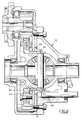
- the differential 12 is disposed in its housing and comprises a housing 16 rotatably supported in the housing by two tapered bearings 17 and 18.
- This differential also comprises, in known manner, a planet carrier 19 and satellites 20, 21 meshing with planetary gears 22 and 23 intended to be connected to transmission shafts not shown in the drawings and which are intended to drive the two wheels front of the vehicle.
- the differential housing 16 comprises a radial flange 24 to which is fixed, by studs 25, a second annular flange 26. Projecting parts 26 a determine the width of the free space formed between the two opposite faces 28, 29 of the flanges 24, 26 for receiving planet gears 30 rotatably mounted on hollow axes 31 and a sun gear 32 which meshes with the planet gears and which is rotatably mounted on a cylindrical surface 33 of the differential housing.
- the satellites 30 can optionally be mounted on needles.
- the two flanges 24 and 26 delimit cylindrical bearing surfaces, aligned 34 and 35 on which a crown 36 is guided.
- This ring has an external toothing 37 which is engaged with the output pinion 13 of the gearbox and an internal toothing 38 which cooperates with the planet gears 30.
- the crown has a T-shaped section whose vertical branch carrying the internal toothing is received and guided laterally in the interval between the two opposite faces of the flanges 24, 26 and whose horizontal branches delimit on one side concave bearing surfaces resting on the bearing surfaces 34, 35 and, on the other side, the external toothing 37.
- the assembly formed by the differential housing 16 acting as planet carrier, the sun gear 32, the satellites 30 and the crown 36 constitutes a planetary gear which occupies a volume usually unused, between the differential and the output pinion of the gearbox and which makes it possible to obtain the two desired speed ranges.
- the device is supplemented by means making it possible to block the planetary train that has just been described at will.
- These means comprise an internal toothing 40 formed on the internal periphery of the flange 26, a plate 41 which is fixed by studs 42 to the differential casing and which has on its internal periphery a toothing 43 identical to that provided on the flange 26.
- the sun gear 32 is also extended by a section of hollow shaft 44 carrying external splines 45.
- a sliding sleeve 46, internally grooved at 47 is slidably mounted on the grooves 45 and comprises on the one hand an external toothing 48 capable of cooperating with one or the other of the two teeth 40 and 43.
- This sliding sleeve is actuated at by means of a fork 49 which can be moved by the user when the vehicle is stationary.
- the user brings the walker 46 in the position shown in Figure 2, position in which this walker makes the sun gear 32 integral with the plate 41 and therefore the housing 10.
- the sun gear 32 thus constitutes a reaction member
- the planet carrier 24, 26 rotates in the same direction as the crown, but slower and the intermediate planetary gear introduces a speed reduction coefficient between the output of the gearbox and the differential, thus allowing to have a shorter range of gear ratios.
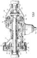
- FIG. 4 shows a transmission for a four-wheel drive vehicle comprising, in a casing 100, a central differential 50 connected to the output of the gearbox, not shown, by a reduction mechanism according to the invention, such as described with reference to FIGS. 1 to 3.
- the input member of this central differential, of the planetary gear type is constituted by its planet carrier 51 which is connected so as to be integral therewith in rotation, with the planet carrier 116 of the reduction mechanism.
- the various elements of the latter are designated by the same reference numbers as in FIGS. 1 to 3.
- the central differential also comprises a sun gear 52 which is integral with the housing of a differential 60 for driving the front wheels of the vehicle, satellites 53 and a crown 54 which drives, via a conical gear 55, a shaft longitudinal transmission 56 connected to the rear wheel differential (not shown).
- the crown 36 is guided on smooth bearings, without the need for additional bearings, which constitutes a simple and space-saving solution.
- the bearing surfaces are preferably the subject of an electrolytic treatment, for example of sulfurization or supersulfurization, or of any other type of appropriate treatment to give them the necessary characteristics of surface condition and resistance. .
- the proposed device therefore constitutes a particularly simple and inexpensive solution, compared to the solutions already known and which can be used in different configurations: vehicle with two or four-wheel drive, in combination with a front differential or with a central or transaxle differential.
Abstract
Description
La présente invention concerne les mécanismes réducteurs et les dispositifs de transmission pour véhicules automobiles.The present invention relates to reduction mechanisms and transmission devices for motor vehicles.
Elle concerne notamment des véhicules dits "tous chemins" c'est à dire présentant des capacités de franchissement supérieures à celles des véhicules routiers normaux mais qui peuvent être néanmoins dérivés de véhicules de série. Ces véhicules peuvent comporter deux ou quatre roues motrices, les deux roues motrices supplémentaires pouvant l'être de façon permanente ou sous la commande du conducteur.It relates in particular to so-called "all-road" vehicles, that is to say having crossing capacities greater than those of normal road vehicles but which can nevertheless be derived from mass-produced vehicles. These vehicles may include two or four drive wheels, the two additional drive wheels may be permanently or under the control of the driver.
On sait que de tels véhicules peuvent parfois être handicapés par un manque de motricité auquel cas il est souhaitable de pouvoir disposer d'une gamme de rapports de vitesses plus courte destinée à compenser ce défaut de motricité. Une solution connue pour pouvoir disposer de cette deuxième gamme de vitesses consiste à prévoir une boîte de vitesses spécifique, équipée d'un mécanisme réducteur qui permet d'établir dans cette boîte de vitesses les deux gammes de rapports souhaitées.It is known that such vehicles can sometimes be handicapped by a lack of traction, in which case it is desirable to be able to have a shorter range of gear ratios intended to compensate for this lack of traction. A known solution for being able to have this second range of speeds consists in providing a specific gearbox, equipped with a reduction mechanism which makes it possible to establish in this gearbox the two ranges of desired ratios.
Une telle solution est à la fois compliquée et chère : en effet, elle implique de pouvoir adapter sur un même véhicule soit une boîte classique, soit une boîte spéciale n'ayant pas le même encombrement. De plus, étant donné que dans un groupe motopropulseur et notamment un groupe motopropulseur disposé transversalement par rapport à la direction longitudinale du véhicule, le carter de la boîte de vitesses est en général intégré au bloc moteur et au carter du différentiel, le fait de devoir disposer de deux boîtes de vitesses différentes a une incidence sur les éléments adjacents du bloc moteur, ce qui est un facteur d'augmentation du coût.Such a solution is both complicated and expensive: indeed, it involves being able to adapt on the same vehicle either a conventional box, or a special box not having the same size. In addition, since in a powertrain and in particular a powertrain arranged transversely to the longitudinal direction of the vehicle, the gearbox casing is generally integrated into the engine block and the differential casing, the fact of having to having two different gearboxes affects the adjacent elements of the engine block, which is a factor of increase in cost.
Enfin, si le réducteur est disposé à l'entrée de la boîte de vitesses, il est nécessaire de surdimensionner celle-ci pour pouvoir transmettre des couples plus élevés lorsque la gamme courte est choisie, ce qui augmente d'autant le coût du dispositif.Finally, if the reducer is placed at the inlet of the gearbox, it is necessary to oversize it in order to be able to transmit higher torques when the short range is chosen, which increases the cost of the device accordingly.
L'objectif qui est ici fixé est de proposer un mécanisme réducteur et un dispositif de transmission qui permettent de disposer de deux gammes de rapport de vitesses sans modification de la boîte de vitesses, dans un encombrement réduit et moyennant un coût le plus faible possible.The objective which is fixed here is to propose a reduction mechanism and a transmission device which make it possible to have two ranges of gear ratio without modification of the gearbox, in a reduced size and at the lowest possible cost.
A cet effet, l'invention a pour objet un mécanisme réducteur du type à train planétaire, comprenant un carter, un porte-satellites monté rotatif dans ce carter, une couronne à dentures externe et interne, un pignon planétaire et des pignons satellites, engrenant avec le planétaire et avec la denture interne de la couronne, caractérisé en ce que le porte-satellites comprend un flasque radial, délimitant au moins une portée cylindrique qui supporte à rotation la couronne.To this end, the subject of the invention is a reduction mechanism of the planetary gear type, comprising a housing, a planet carrier rotatably mounted in this housing, an external and internal gear ring, a planetary gear and planet gears, meshing with the sun gear and with the internal toothing of the crown, characterized in that the planet carrier comprises a radial flange, delimiting at least one cylindrical bearing which rotatably supports the crown.
Suivant d'autres caractéristiques :
- le flasque radial du porte-satellites porte un flasque radial parallèle, qui délimite avec lui un espace dans lequel sont reçus les pignons satellites et qui délimite aussi une portée cylindrique située dans le prolongement de la portée cylindrique dudit flasque radial, ces deux portées assurant le guidage en rotation de la couronne ;
- la couronne a une section transversale en forme de T dont la branche verticale est reçue et guidée latéralement dans l'intervalle entre les deux flasques et dont les parties inférieures des deux branches horizontales coopèrent avec les portées cylindriques des deux flasques ;
- le porte-satellites comprend une partie axiale délimitant une portée cylindrique qui supporte à rotation le pignon planétaire ;
- il est prévu des moyens permettant de placer le mécanisme réducteur dans l'un ou l'autre de deux états, comprenant un manchon balladeur, monté coulissant entre deux positions, une première position dans laquelle il rend solidaires deux éléments du mécanisme réducteur à train planétaire, bloquant ainsi ce dernier, et une deuxième position dans laquelle il libère ces deux éléments et bloque l'un d'entre eux par rapport au carter ;
- le manchon balladeur comporte des cannelures internes toujours en prise avec des cannelures externes correspondantes prévues sur un prolongement axial du planétaire du mécanisme réducteur et au moins une denture externe pouvant être amenée en prise, sélectivement, soit avec une denture interne prévue sur le porte-satellites du mécanisme réducteur, soit avec une denture interne prévue sur une pièce solidaire du carter;
- la denture interne prévue sur le porte-satellites est ménagée sur le deuxième flasque fixé sur le flasque radial du porte-satellites.
- the radial flange of the planet carrier carries a parallel radial flange, which delimits with it a space in which the planet gears are received and which also delimits a cylindrical bearing located in the extension of the cylindrical bearing of said radial flange, these two bearing ensuring guiding in rotation of the crown;
- the crown has a T-shaped cross section whose vertical branch is received and guided laterally in the gap between the two flanges and whose lower parts of the two horizontal branches cooperate with the cylindrical bearings of the two flanges;
- the planet carrier comprises an axial part delimiting a cylindrical bearing which rotatably supports the planetary pinion;
- means are provided for placing the reduction mechanism in one or the other of two states, comprising a sliding sleeve, mounted sliding between two positions, a first position in which it makes two elements of the reduction mechanism with planetary gear integral , thus blocking the latter, and a second position in which it releases these two elements and blocks one of them relative to the casing;
- the sliding sleeve has internal grooves always in engagement with corresponding external grooves provided on an axial extension of the planetary of the reduction mechanism and at least one external toothing which can be brought into engagement, selectively, either with an internal toothing provided on the planet carrier the reduction mechanism, either with internal toothing provided on a part secured to the casing;
- the internal toothing provided on the planet carrier is formed on the second flange fixed on the radial flange of the planet carrier.
L'invention a également pour objet un dispositif de transmission comprenant une boîte de vitesses et au moins un différentiel logés dans au moins un carter, la boîte de vitesses comportant un pignon de sortie et le différentiel comportant un boîtier qui constitue son organe d'entrée et qui est relié à une couronne en prise avec le pignon de sortie de la boîte, caractérisé en ce qu'un mécanisme réducteur à train planétaire tel que défini ci-dessus est interposé entre la couronne et le boîtier du différentiel, des moyens étant prévus pour pouvoir placer ce mécanisme réducteur dans l'un ou l'autre de deux états : un premier état dans lequel il est bloqué et n'introduit aucune réduction de vitese et un deuxième état dans lequel il fonctionne en réducteur de vitesse.The invention also relates to a transmission device comprising a gearbox and at least one differential housed in at least one housing, the gearbox comprising an output pinion and the differential comprising a housing which constitutes its input member. and which is connected to a ring gear engaged with the gearbox output pinion, characterized in that a planetary gear reduction mechanism as defined above is interposed between the ring gear and the differential housing, means being provided to be able to place this reducing mechanism in one or the other of two states: a first state in which it is blocked and does not introduce any reduction in speed and a second state in which it operates as a speed reducer.
L'invention va être décrite plus en détail ci-dessous en se référant aux dessins annexés, donnés uniquement à titre d'exemples et sur lesquels :
- La Figure 1 est une vue en coupe suivant la ligne 1-1 de la Figure 3 d'une partie d'un dispositif de transmission selon l'invention ;
- La Figure 2 est une vue analogue à celle de la Figure 1 montrant le dispositif dans une deuxième position d'utilisation ;
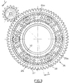
- La Figure 3 est une vue en élévation latérale du réducteur, le boîtier de différentiel étant omis ; et
- La Figure 4 est une vue en coupe d'une variante d'utilisation d'un mécanisme réducteur selon l'invention.
- Figure 1 is a sectional view along line 1-1 of Figure 3 of a portion of a transmission device according to the invention;
- Figure 2 is a view similar to that of Figure 1 showing the device in a second position of use;
- Figure 3 is a side elevational view of the reducer, the differential housing being omitted; and
- Figure 4 is a sectional view of an alternative use of a reduction mechanism according to the invention.
On a représenté aux Figures 1 à 3 une partie d'un groupe motopropulseur de véhicule automobile, qui est disposé transversalement par rapport à la direction longitudinale de ce véhicule. Ne sont représentées que les parties du dispositif utiles à la compréhension de l'invention. C'est ainsi que le moteur proprement dit et l'essentiel de la boîte de vitesses n'ont pas été représentés sur ces dessins.There is shown in Figures 1 to 3 a part of a motor vehicle powertrain, which is arranged transversely to the longitudinal direction of this vehicle. Only the parts of the device useful for understanding the invention are shown. This is how the engine proper and most of the gearbox have not been shown in these drawings.
On voit sur la Figure 1 une partie 10 du carter de la boîte de vitesses 11 et du différentiel 12, ainsi que le pignon 13 de sortie de la boîte de vitesses. L'arbre 14 dont est solidaire ce pignon de sortie est monté rotatif dans le carter par des roulements tels que le roulement 15.We see in Figure 1 a
Le différentiel 12 est disposé dans son carter et comporte un boîtier 16 supporté à rotation dans le carter par deux roulements coniques 17 et 18. Ce différentiel comprend par ailleurs, de façon connue, un porte-satellites 19 et des satellites 20, 21 engrenant avec des pignons planétaires 22 et 23 destinés à être reliés à des arbres de transmission non représentés aux dessins et qui sont destinés à entraîner les deux roues avant du véhicule.The
On n'a pas davantage représenté aux dessins des moyens permettant d'entraîner à partir du boîtier de différentiel un essieu arrière moteur du véhicule.Nor has there been shown in the drawings means making it possible to drive from the differential housing a driving rear axle of the vehicle.
Le boîtier 16 de différentiel comporte un flasque radial 24 auquel est fixé, par des goujons 25, un deuxième flasque annulaire 26. Des parties en saillie 26a déterminent la largeur de l'espace libre ménagé entre les deux faces en regard 28, 29 des flasques 24, 26 pour recevoir des pignons satellites 30 montés rotatifs sur des axes creux 31 et un planétaire 32 qui engrène avec les pignons satellites et qui est monté rotatif sur une portée cylindrique 33 du boîtier du différentiel. Les satellites 30 peuvent éventuellement être montés sur aiguilles.The
Par ailleurs, les deux flasques 24 et 26 délimitent des surfaces cylindriques de portée, alignées 34 et 35 sur lesquelles est guidée une couronne 36.Furthermore, the two
Cette couronne comporte une denture externe 37 qui est en prise avec le pignon de sortie 13 de la boîte de vitesses et une denture interne 38 qui coopère avec les pignons satellites 30.This ring has an
La couronne a une section en forme de T dont la branche verticale portant la denture interne est reçue et guidée latéralement dans l'intervalle entre les deux faces en regard des flasques 24, 26 et dont les branches horizontales délimitent d'un côté des portées concaves reposant sur les portées 34, 35 et, de l'autre côté la denture externe 37.The crown has a T-shaped section whose vertical branch carrying the internal toothing is received and guided laterally in the interval between the two opposite faces of the
L'ensemble formé par le boîtier de différentiel 16 faisant office de porte-satellites, le planétaire 32, les satellites 30 et la couronne 36 constitue un train planétaire qui occupe un volume habituellement inutilisé, entre le différentiel et le pignon de sortie de la boîte de vitesses et qui permet d'obtenir les deux gammes de vitesse souhaitées.The assembly formed by the
A cet effet, le dispositif est complété par des moyens permettant de bloquer à volonté le train planétaire que l'on vient de décrire. Ces moyens comprennent une denture interne 40 ménagée sur la périphérie interne du flasque 26, une plaque 41 qui est fixée par des goujons 42 au carter de différentiel et qui comporte sur sa périphérie interne une denture 43 identique à celle prévue sur le flasque 26.To this end, the device is supplemented by means making it possible to block the planetary train that has just been described at will. These means comprise an
Le planétaire 32 est par ailleurs prolongé par un tronçon d'arbre creux 44 portant des cannelures externes 45.The
Un manchon balladeur 46, cannelé intérieurement en 47 est monté coulissant sur les cannelures 45 et comporte d'une part une denture externe 48 susceptible de coopérer avec l'une ou l'autre des deux dentures 40 et 43. Ce manchon balladeur est actionné au moyen d'une fourchette 49 qui peut être déplacée par l'utilisateur lorsque le véhicule est à l'arrêt.A
Le fonctionnement d'un tel dispositif est le suivant : lorsque le manchon balladeur 46 occupe la position représentée sur la Figure 1, il solidarise le planétaire 32 et le porte-satellites 24, 26 du train interposé entre la couronne 36 et le différentiel 12. Cela a pour effet de bloquer ce train planétaire de sorte que la couronne 36 est rendue solidaire du boîtier 16 de différentiel et que le rapport établi dans la boîte de vitesses n'est pas modifié entre la sortie de la boîte et l'entrée du différentiel. On établit ainsi dans la transmission une gamme longue de rapports de vitesses.The operation of such a device is as follows: when the
Pour pouvoir disposer d'une motricité plus importante, l'utilisateur amène le balladeur 46 dans la position représentée à la Figure 2, position dans laquelle ce balladeur rend le planétaire 32 solidaire de la plaque 41 et par conséquent du carter 10. Le planétaire 32 constitue ainsi un organe de réaction, le porte-satellites 24, 26 tourne dans le même sens que la couronne, mais moins vite et le train planétaire intermédiaire introduit un coefficient de réduction de vitesse entre la sortie de la boîte et le différentiel, permettant ainsi de disposer d'une gamme plus courte de rapports de vitesses.To be able to have greater traction, the user brings the
On a représenté sur la figure 4 une transmission pour véhicule à quatre roues motrices comprenant, dans un carter 100, un différentiel central 50 relié à la sortie de la boîte de vitesse, non représentée, par un mécanisme réducteur suivant l'invention, tel que décrit à propos des figures 1 à 3. L'organe d'entrée de ce différentiel central, du type à train épicycloïdal, est constitué par son porte-satellites 51 qui est relié de façon à en être solidaire en rotation, au porte-satellites 116 du mécanisme réducteur. Les différents éléments de ce dernier sont désignés par les mêmes numéros de référence que sur les figures 1 à 3.FIG. 4 shows a transmission for a four-wheel drive vehicle comprising, in a
Le différentiel central comporte par ailleurs un planétaire 52 qui est solidaire du boîtier d'un différentiel 60 d'entraînement des roues avant du véhicule, des satellites 53 et une couronne 54 qui entraîne par l'intermédiaire d'un renvoi conique 55, un arbre longitudinal de transmission 56 relié au différentiel des roues arrière (non représenté).The central differential also comprises a
On ne décrira pas davantage ce dispositif dont l'originalité réside principalement dans l'utilisation d'un mécanisme réducteur suivant l'invention logé dans le carter 10.This device will not be described further, the originality of which mainly lies in the use of a reduction mechanism according to the invention housed in the
Dans l'agencement selon l'invention, la couronne 36 est guidée sur des portées lisses, sans qu'il soit nécessaire de prévoir des roulements supplémentaires, ce qui constitue une solution simple et peu encombrante. A cet égard, les surfaces de portée font de préférence l'objet d'un traitement électrolytique, par exemple de sulfuration ou de sursulfuration, ou de tout autre type de traitement approprié pour leur donner les caractéristiques nécessaires d'état de surface et de résistance.In the arrangement according to the invention, the
On notera pour les deux modes de réalisation que la présence d'une gamme longue et d'une gamme courte est obtenue par des moyens simples et peu encombrants puisque le train réducteur supplémentaire est disposé dans l'encombrement normal du groupe motopropulseur, sans qu'il soit nécessaire de modifier sensiblement les carters. L'adjonction de la plaque 41 ne pose pas de problème particulier.It will be noted for the two embodiments that the presence of a long range and of a short range is obtained by simple and space-saving means since the additional reduction gear is disposed in the normal size of the powertrain, without that it is necessary to modify the housings significantly. The addition of the
Le fait de disposer le train réducteur en aval de la boîte de vitesses permet de ne pas surdimensionner cette dernière qui demeure inchangée par rapport à sa configuration habituelle.The fact of having the reduction gear downstream of the gearbox makes it possible not to oversize the latter which remains unchanged compared to its usual configuration.
Le dispositif proposé constitue donc une solution particulièrement simple et peu onéreuse, par rapport aux solutions déjà connues et qui peut être utilisée dans différentes configurations : véhicule à deux ou quatre roues motrices, en association avec un différentiel avant ou avec un différentiel central ou interponts.The proposed device therefore constitutes a particularly simple and inexpensive solution, compared to the solutions already known and which can be used in different configurations: vehicle with two or four-wheel drive, in combination with a front differential or with a central or transaxle differential.
Claims (8)
Applications Claiming Priority (2)
| Application Number | Priority Date | Filing Date | Title |
|---|---|---|---|
| FR9315117 | 1993-12-15 | ||
| FR9315117A FR2713734B1 (en) | 1993-12-15 | 1993-12-15 | Reduction mechanism and transmission device with two ranges of speed ratios, for motor vehicle. |
Publications (2)
| Publication Number | Publication Date |
|---|---|
| EP0658705A1 true EP0658705A1 (en) | 1995-06-21 |
| EP0658705B1 EP0658705B1 (en) | 1997-08-27 |
Family
ID=9453991
Family Applications (1)
| Application Number | Title | Priority Date | Filing Date |
|---|---|---|---|
| EP94402860A Expired - Lifetime EP0658705B1 (en) | 1993-12-15 | 1994-12-12 | Speed-reducing mechanism and transmission device with two ranges for a motor vehicle |
Country Status (5)
| Country | Link |
|---|---|
| US (1) | US5554080A (en) |
| EP (1) | EP0658705B1 (en) |
| AT (1) | ATE157432T1 (en) |
| DE (1) | DE69405202T2 (en) |
| FR (1) | FR2713734B1 (en) |
Cited By (4)
| Publication number | Priority date | Publication date | Assignee | Title |
|---|---|---|---|---|
| EP2444696A1 (en) * | 2010-10-22 | 2012-04-25 | Volvo Car Corporation | Overdrive unit |
| CN104179926A (en) * | 2014-09-04 | 2014-12-03 | 中国人民解放军军事交通学院 | Non-bevel gear mechanism |
| CN104728387A (en) * | 2015-03-27 | 2015-06-24 | 中国人民解放军军事交通学院 | Three-fork-shaft-type noncircular bevel gear limited slip differential |
| WO2019068417A1 (en) | 2017-10-03 | 2019-04-11 | Renault S.A.S | Gear-splitting differential transmission device and four-wheel drive transmission |
Families Citing this family (11)
| Publication number | Priority date | Publication date | Assignee | Title |
|---|---|---|---|---|
| US5888165A (en) * | 1997-05-09 | 1999-03-30 | Ford Global Technologies, Inc. | Multiple-speed axle mechanism |
| US6074321A (en) * | 1997-09-30 | 2000-06-13 | Aisin Seiki Kabushiki Kaisha | Transaxle assembly |
| JPH11344100A (en) * | 1998-06-02 | 1999-12-14 | Zexel:Kk | Power transmission device |
| US6193629B1 (en) | 1999-05-07 | 2001-02-27 | Ford Global Technologies, Inc. | Shifting mechanism |
| US6165103A (en) * | 1999-05-07 | 2000-12-26 | Visteon Global Technologies, Inc. | Shifting mechanism |
| US6729991B1 (en) * | 1999-12-17 | 2004-05-04 | Bosch Automotive Systems Corporation | Combined differential gear device |
| JP3853631B2 (en) | 2001-10-23 | 2006-12-06 | 株式会社ジェイテクト | Hybrid differential gear unit |
| JP4815187B2 (en) * | 2005-10-25 | 2011-11-16 | 本田技研工業株式会社 | Vehicle power transmission device |
| RU2011122726A (en) * | 2008-11-07 | 2012-12-20 | МАГНА ПАУЭРТРЕЙН ЮЭсЭй, ИНК. | ELECTRIC DRIVE FOR A TWO-SPEED DRIVING AXLE IN A TRANSMISSION UNIT |
| DE102017004931A1 (en) | 2016-12-21 | 2018-06-21 | Daimler Ag | Transmission device for a motor vehicle |
| US11724593B2 (en) * | 2021-07-20 | 2023-08-15 | Dana Automotive Systems Group, Llc | Electric axle assembly and operating method |
Citations (5)
| Publication number | Priority date | Publication date | Assignee | Title |
|---|---|---|---|---|
| FR940256A (en) * | 1947-02-01 | 1948-12-08 | Pulley or wheel with reduction or multiplication of speed | |
| FR1109537A (en) * | 1954-07-30 | 1956-01-30 | Rech S Pour Engins Mecaniques | Epicyclic reversing gearbox |
| FR1162024A (en) * | 1955-12-16 | 1958-09-08 | Daimler Benz Ag | Axle drive for motor cars with differential and two-speed gear change, especially additional gear change |
| FR2532708A3 (en) * | 1981-08-24 | 1984-03-09 | Clocheau Michel | Automatic transmission for transverse engined vehicles. |
| EP0421112A2 (en) * | 1989-10-02 | 1991-04-10 | Matex Co. Ltd. | Variable drive with planetary gearing |
Family Cites Families (7)
| Publication number | Priority date | Publication date | Assignee | Title |
|---|---|---|---|---|
| US4462271A (en) * | 1978-11-24 | 1984-07-31 | Mack Trucks, Inc. | Automatic differential control apparatus |
| US4440042A (en) * | 1981-07-29 | 1984-04-03 | Borg-Warner Corporation | Helical planetary gear assembly |
| US4677875A (en) * | 1985-12-09 | 1987-07-07 | American Motors Corporation | Transfer case for multiple drive axle vehicle |
| US4677873A (en) * | 1985-12-23 | 1987-07-07 | Chrysler Motors Corporation | Transfer case with inter-axle dual-planetary differential |
| US5042610A (en) * | 1987-09-01 | 1991-08-27 | Mazda Motor Corporation | Four-wheel drive vehicle |
| US4920828A (en) * | 1988-02-08 | 1990-05-01 | Mazda Motor Corporation | Planetary gear type transmission |
| US5176590A (en) * | 1991-07-29 | 1993-01-05 | Dana Corporation | Planetary locking differential |
-
1993
- 1993-12-15 FR FR9315117A patent/FR2713734B1/en not_active Expired - Fee Related
-
1994
- 1994-12-12 DE DE69405202T patent/DE69405202T2/en not_active Expired - Fee Related
- 1994-12-12 AT AT94402860T patent/ATE157432T1/en not_active IP Right Cessation
- 1994-12-12 EP EP94402860A patent/EP0658705B1/en not_active Expired - Lifetime
- 1994-12-15 US US08/356,893 patent/US5554080A/en not_active Expired - Fee Related
Patent Citations (5)
| Publication number | Priority date | Publication date | Assignee | Title |
|---|---|---|---|---|
| FR940256A (en) * | 1947-02-01 | 1948-12-08 | Pulley or wheel with reduction or multiplication of speed | |
| FR1109537A (en) * | 1954-07-30 | 1956-01-30 | Rech S Pour Engins Mecaniques | Epicyclic reversing gearbox |
| FR1162024A (en) * | 1955-12-16 | 1958-09-08 | Daimler Benz Ag | Axle drive for motor cars with differential and two-speed gear change, especially additional gear change |
| FR2532708A3 (en) * | 1981-08-24 | 1984-03-09 | Clocheau Michel | Automatic transmission for transverse engined vehicles. |
| EP0421112A2 (en) * | 1989-10-02 | 1991-04-10 | Matex Co. Ltd. | Variable drive with planetary gearing |
Cited By (6)
| Publication number | Priority date | Publication date | Assignee | Title |
|---|---|---|---|---|
| EP2444696A1 (en) * | 2010-10-22 | 2012-04-25 | Volvo Car Corporation | Overdrive unit |
| US8568266B2 (en) | 2010-10-22 | 2013-10-29 | Volvo Car Corporation | Overdrive unit |
| CN104179926A (en) * | 2014-09-04 | 2014-12-03 | 中国人民解放军军事交通学院 | Non-bevel gear mechanism |
| CN104728387A (en) * | 2015-03-27 | 2015-06-24 | 中国人民解放军军事交通学院 | Three-fork-shaft-type noncircular bevel gear limited slip differential |
| CN104728387B (en) * | 2015-03-27 | 2017-06-30 | 中国人民解放军军事交通学院 | The slip-limiting differential mechanism with noncircular bevel gear of trident shaft type |
| WO2019068417A1 (en) | 2017-10-03 | 2019-04-11 | Renault S.A.S | Gear-splitting differential transmission device and four-wheel drive transmission |
Also Published As
| Publication number | Publication date |
|---|---|
| US5554080A (en) | 1996-09-10 |
| DE69405202D1 (en) | 1997-10-02 |
| DE69405202T2 (en) | 1998-03-26 |
| EP0658705B1 (en) | 1997-08-27 |
| FR2713734A1 (en) | 1995-06-16 |
| ATE157432T1 (en) | 1997-09-15 |
| FR2713734B1 (en) | 1996-03-01 |
Similar Documents
| Publication | Publication Date | Title |
|---|---|---|
| EP0658705B1 (en) | Speed-reducing mechanism and transmission device with two ranges for a motor vehicle | |
| CA1314414C (en) | Transmission gearbox with one transmission input shaft and two output shafts | |
| EP0265297B1 (en) | Differential transmission device, particularly for motor vehicles | |
| EP0094870A1 (en) | Inter-axle differential gearing for a four-wheel drive vehicle | |
| FR2591157A1 (en) | TRANSFER BOX | |
| FR2504867A1 (en) | DRIVE SYSTEM FOR A FOUR-WHEELED VEHICLE | |
| FR2505269A1 (en) | DRIVE SYSTEM FOR A FOUR-WHEELED VEHICLE | |
| WO2012156613A1 (en) | Gear-shifting device for a bicycle | |
| FR2826400A1 (en) | MANUAL BLIND DRIVE DEVICE INCLUDING AN EPICYCLOIDAL REDUCER | |
| FR2780213A1 (en) | Compact electric drive unit for automobile | |
| EP0159925A1 (en) | Transmission device for four-wheel drive vehicles | |
| EP0243266B1 (en) | Front wheel drive vehicle transmission device | |
| EP0241382B1 (en) | Rear axle for a four-wheel drive vehicle | |
| FR2797671A1 (en) | BLOCKING DIFFERENTIAL GEAR | |
| FR2587077A1 (en) | DRIVE CHANGING APPARATUS IN FORWARD-REVERSE AND TRANSMISSION COMPRISING SAME | |
| FR2539356A1 (en) | ARRANGEMENT OF TRANSMISSION MECHANISMS OF A FOUR-DRIVE VEHICLE | |
| EP0041730A2 (en) | Change speed transmission with four forward and two reverse speeds | |
| EP0574289B1 (en) | Ground clearance in creasing gearbox for fore wheel drive, transversal engine, vehicles | |
| EP0281847B1 (en) | Dental hand piece | |
| FR2562000A1 (en) | Transmission device with two differentials, for vehicle with four driving wheels | |
| FR2667374A1 (en) | Device for transmitting a driving torque for a motor vehicle driving wheel with a rolling-contact bearing and a speed reducer which are built into the wheel | |
| FR2896469A1 (en) | Steering shaft for steering wheel of motor vehicle, has helicoidal compression spring arranged on countershaft, exerting axial force defined on upper and lower pinions of countershaft so that pinions tend to move away from one another | |
| FR2706369A1 (en) | Wheel suspension of the trailing arm type for a motor vehicle | |
| EP0307269B1 (en) | Differential transmission for a motor vehicle | |
| EP1097317A1 (en) | Transmission unit with reversing mechanism mounted between a gearbox and at least two drive wheels |
Legal Events
| Date | Code | Title | Description |
|---|---|---|---|
| PUAI | Public reference made under article 153(3) epc to a published international application that has entered the european phase |
Free format text: ORIGINAL CODE: 0009012 |
|
| 17P | Request for examination filed |
Effective date: 19950403 |
|
| AK | Designated contracting states |
Kind code of ref document: A1 Designated state(s): AT DE ES GB IT |
|
| 17Q | First examination report despatched |
Effective date: 19960219 |
|
| GRAG | Despatch of communication of intention to grant |
Free format text: ORIGINAL CODE: EPIDOS AGRA |
|
| GRAH | Despatch of communication of intention to grant a patent |
Free format text: ORIGINAL CODE: EPIDOS IGRA |
|
| GRAH | Despatch of communication of intention to grant a patent |
Free format text: ORIGINAL CODE: EPIDOS IGRA |
|
| GRAA | (expected) grant |
Free format text: ORIGINAL CODE: 0009210 |
|
| AK | Designated contracting states |
Kind code of ref document: B1 Designated state(s): AT DE ES GB IT |
|
| PG25 | Lapsed in a contracting state [announced via postgrant information from national office to epo] |
Ref country code: IT Free format text: LAPSE BECAUSE OF FAILURE TO SUBMIT A TRANSLATION OF THE DESCRIPTION OR TO PAY THE FEE WITHIN THE PRE;WARNING: LAPSES OF ITALIAN PATENTS WITH EFFECTIVE DATE BEFORE 2007 MAY HAVE OCCURRED AT ANY TIME BEFORE 2007. THE CORRECT EFFECTIVE DATE MAY BE DIFFERENT FROM THE ONE RECORDED.SCRIBED TIME-LIMIT Effective date: 19970827 Ref country code: GB Free format text: LAPSE BECAUSE OF FAILURE TO SUBMIT A TRANSLATION OF THE DESCRIPTION OR TO PAY THE FEE WITHIN THE PRESCRIBED TIME-LIMIT Effective date: 19970827 Ref country code: ES Free format text: THE PATENT HAS BEEN ANNULLED BY A DECISION OF A NATIONAL AUTHORITY Effective date: 19970827 Ref country code: AT Effective date: 19970827 |
|
| REF | Corresponds to: |
Ref document number: 157432 Country of ref document: AT Date of ref document: 19970915 Kind code of ref document: T |
|
| REF | Corresponds to: |
Ref document number: 69405202 Country of ref document: DE Date of ref document: 19971002 |
|
| GBV | Gb: ep patent (uk) treated as always having been void in accordance with gb section 77(7)/1977 [no translation filed] |
Effective date: 19970827 |
|
| PLBE | No opposition filed within time limit |
Free format text: ORIGINAL CODE: 0009261 |
|
| STAA | Information on the status of an ep patent application or granted ep patent |
Free format text: STATUS: NO OPPOSITION FILED WITHIN TIME LIMIT |
|
| 26N | No opposition filed | ||
| PGFP | Annual fee paid to national office [announced via postgrant information from national office to epo] |
Ref country code: DE Payment date: 20001117 Year of fee payment: 7 |
|
| PG25 | Lapsed in a contracting state [announced via postgrant information from national office to epo] |
Ref country code: DE Free format text: LAPSE BECAUSE OF NON-PAYMENT OF DUE FEES Effective date: 20020702 |