EP0658695B1 - Befestigungselement aus Kunstoff zum Einstecken in einer Öffnung einer Platte oder dergleichen - Google Patents
Befestigungselement aus Kunstoff zum Einstecken in einer Öffnung einer Platte oder dergleichen Download PDFInfo
- Publication number
- EP0658695B1 EP0658695B1 EP19940402667 EP94402667A EP0658695B1 EP 0658695 B1 EP0658695 B1 EP 0658695B1 EP 19940402667 EP19940402667 EP 19940402667 EP 94402667 A EP94402667 A EP 94402667A EP 0658695 B1 EP0658695 B1 EP 0658695B1
- Authority
- EP
- European Patent Office
- Prior art keywords
- shaft
- panel
- barrel
- aperture
- tongue
- Prior art date
- Legal status (The legal status is an assumption and is not a legal conclusion. Google has not performed a legal analysis and makes no representation as to the accuracy of the status listed.)
- Expired - Lifetime
Links
Images

Classifications
-
- F—MECHANICAL ENGINEERING; LIGHTING; HEATING; WEAPONS; BLASTING
- F16—ENGINEERING ELEMENTS AND UNITS; GENERAL MEASURES FOR PRODUCING AND MAINTAINING EFFECTIVE FUNCTIONING OF MACHINES OR INSTALLATIONS; THERMAL INSULATION IN GENERAL
- F16B—DEVICES FOR FASTENING OR SECURING CONSTRUCTIONAL ELEMENTS OR MACHINE PARTS TOGETHER, e.g. NAILS, BOLTS, CIRCLIPS, CLAMPS, CLIPS OR WEDGES; JOINTS OR JOINTING
- F16B37/00—Nuts or like thread-engaging members
- F16B37/04—Devices for fastening nuts to surfaces, e.g. sheets, plates
- F16B37/041—Releasable devices
- F16B37/043—Releasable devices with snap action
-
- F—MECHANICAL ENGINEERING; LIGHTING; HEATING; WEAPONS; BLASTING
- F16—ENGINEERING ELEMENTS AND UNITS; GENERAL MEASURES FOR PRODUCING AND MAINTAINING EFFECTIVE FUNCTIONING OF MACHINES OR INSTALLATIONS; THERMAL INSULATION IN GENERAL
- F16B—DEVICES FOR FASTENING OR SECURING CONSTRUCTIONAL ELEMENTS OR MACHINE PARTS TOGETHER, e.g. NAILS, BOLTS, CIRCLIPS, CLAMPS, CLIPS OR WEDGES; JOINTS OR JOINTING
- F16B21/00—Means for preventing relative axial movement of a pin, spigot, shaft or the like and a member surrounding it; Stud-and-socket releasable fastenings
- F16B21/06—Releasable fastening devices with snap-action
- F16B21/08—Releasable fastening devices with snap-action in which the stud, pin, or spigot has a resilient part
- F16B21/086—Releasable fastening devices with snap-action in which the stud, pin, or spigot has a resilient part the shank of the stud, pin or spigot having elevations, ribs, fins or prongs intended for deformation or tilting predominantly in a direction perpendicular to the direction of insertion
-
- F—MECHANICAL ENGINEERING; LIGHTING; HEATING; WEAPONS; BLASTING
- F16—ENGINEERING ELEMENTS AND UNITS; GENERAL MEASURES FOR PRODUCING AND MAINTAINING EFFECTIVE FUNCTIONING OF MACHINES OR INSTALLATIONS; THERMAL INSULATION IN GENERAL
- F16B—DEVICES FOR FASTENING OR SECURING CONSTRUCTIONAL ELEMENTS OR MACHINE PARTS TOGETHER, e.g. NAILS, BOLTS, CIRCLIPS, CLAMPS, CLIPS OR WEDGES; JOINTS OR JOINTING
- F16B5/00—Joining sheets or plates, e.g. panels, to one another or to strips or bars parallel to them
- F16B5/02—Joining sheets or plates, e.g. panels, to one another or to strips or bars parallel to them by means of fastening members using screw-thread
- F16B5/025—Joining sheets or plates, e.g. panels, to one another or to strips or bars parallel to them by means of fastening members using screw-thread specially designed to compensate for misalignement or to eliminate unwanted play
Definitions
- the main subject of the present invention is a plastic fastener insertable into the orifice of a panel or any part in accordance with the preamble of claim 1 (FR-A-2 060 917).
- This attachment element can cooperate for example with a screw to assemble panels or analogues.
- Such fasteners generally include a bole and two elastic and opposite tabs taking birth on the barrel and whose free ends are spaced from barrel to allow element retention of attachment in the hole of the panel, once this element inserted there.
- the object of the present invention is to remedy this disadvantage by proposing a fastening element whose retaining tabs on the panel will still play and fully their role after crossing by the fastening element of the hole in the panel.
- the subject of the invention is an element fastener having the features of claim 1.
- Each link in the rest position and with a view to above has a V shape with two branches are respectively connected to the tongue and to the barrel.
- the fastener according to this invention is still characterized in that the barrel has two tongues opposite, each connected to the barrel by two links cited above.
- the two links belonging to each tongue and to the barrel are located in the same horizontal plane or in a different shot.
- the upper face of the barrel has a multiplicity of pilot holes not opening only on the side of this upper face.
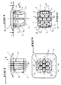
- Figure 1 is a side view in elevation of a plastic fastener according to this invention.
- Figure 2 is a sectional view along line II-II of figure 1.
- Figure 3 is another side view and in elevation of this fastener according to arrow III of the figure 1.
- Figure 4 is a plan and top view of the fastening element according to arrow IV of the figure 3.
- Figure 5 is an exterior and side view of the clip, similar to Figure 1 and showing said clip in mounted position on a panel to be assembled with a second panel, a breakout having been drilled at a pilot hole in the element barrel of attachment.
- Figure 6 is a partial plan view of the panel provided with an orifice to receive the attachment element.
- a fastening element is made in one molded plastic part and includes essentially a barrel 1 which can be inserted in the orifice 2 a P panel, for example, and fitted at the top an upper face 3 bearing on the panel P, as you can clearly see it in figure 5.
- Barrel 1 presents, in cross section, substantially the square shape, two opposite sides of which are respectively provided with a tongue 4 making laterally protruding from the barrel 1.
- each tab 4 has a lower end 4a originating on the barrel 1 on the side of its lower part, and one end superior or free 4b likely to bear on the underside of panel P, so that when the keg 1 is mounted on said panel, it cannot be extract, as is easily understood by referring to again in Figure 5.
- each tab 4 is preferably provided at its free end 4b with two elastically deformable links 5 connecting said free end 4b in barrel 1.
- the free end 4b of one of the tabs 4 is connected to the barrel by two elastic links 5a, 5b, while the free end 4b of the other tab 4 is connected to the barrel 1 by two elastic links 5c and 5d, each link being provided on each side of the tongue.
- each link 5a, 5b, 5c and 5d have a V shape, both of which branches are respectively connected to the tongue 4 and at barrel 1 and whose point 6 is directed towards the outside of the space between the tabs 4 and the barrel 1.
- the point 6 of the V of the elastic links 5 will have sort of a hinge function requesting constantly the tabs 4 in position separated from the barrel 1, as will be explained in detail later about of operation.
- the two elastic links 5 belonging to the free end 4b of each tab 4 are located in a horizontal plane different, mainly for molding reasons. More specifically, as can be seen in the figures 1 and 3, the links 5a and 5b of a tongue are offset vertically, as well as links 5c and 5d of the other tab. But, we could perfectly, without depart from the scope of the invention, provide that the links of the two tabs are all located in the same horizontal plane. Or that the two links 5 of a tongue are in the same plane, and that the two links of the other tab are also in the same plane, but vertically offset from the plane cited first.
- the barrel 1 has a multiplicity of pilot holes 7 emerging on the upper and support face 3, but not opening not on the side of the lower part of the barrel 1.
- pilot holes 7 allow the introduction of a screw V in barrel 1 without trial and error, that is to say whatever either the position of the screw to the right of the face upper 3 belonging to said barrel.
- the number of links elastically deformable between the tabs and the barrel 1 can be any, that is, less than or greater than two.
- the relative position of flexible links can to be arbitrary, as well as their form which could perfectly, without departing from the framework of the invention, be different from that of a V, at the provided that this form acts positively on tabs to constantly urge them into position removed from the barrel.
- the invention therefore includes all equivalents techniques of the means described as well as their combinations, if these are performed according to its mind.
Landscapes
- Engineering & Computer Science (AREA)
- General Engineering & Computer Science (AREA)
- Mechanical Engineering (AREA)
- Insertion Pins And Rivets (AREA)
- Dowels (AREA)
Claims (3)
- Befestigungselement aus Kunststoff, das geeignet ist, z.B. eine Mutter zu Bilden und das in die Öffnung (2) einer Platte oder dergleichen (P) einsteckbar ist, derjenigen Gattung, mit einem Schaft (1) und von dem Schaft (1) seitwärts vorspringenden biegsamen entgegengesetzten Zungen (4), die mit ihrem freien Ende (4b) den Schaft (1) an der Platte (P) nach dem Einstecken des Schaftes in die Öffnung (2) der Platte zurückhalten, wobei jede Zunge (4) mit ihrem freien Ende (4b) durch wenigstens einen elastisch verformbaren Verbindungsteil (5) mit dem Schaft (1) verbunden ist, dadurch gekennzeichnet, daß jeder Verbindungsteil (5a, 5b, 5c, 5d) sich entlang einer senkrecht zur Längsachse des Schaftes verlaufenden Ebene erstreckt und in der Ruhestellung und in Axialansicht die Gestalt eines V's aufweist, dessen beide Schenkel jeweils mit jeder Seite der Zunge (4) und mit dem Schaft (1) verbunden sind und dessen Spitze (6) nach aussen des zwischen den Zungen (4) und dem Schaft (1) gelegenen Raumes gerichtet ist, um ein Scharnier zu bilden, das die Zungen (4) stets zu der von dem Schaft (1) entfernten Stellung hin beaufschlagt und das sich nach Durchgang der Öffnung (2) der Platte (P) entspannt.
- Befestigungselement gemäß Anspruch 1, dadurch gekennzeichnet, daß die zu jeder Zunge (4) und zu dem Schaft (1) gehörenden beiden Verbindungsteile (5a, 5b-5c, 5d) in einer selben senkrecht zur Längsachse des Schaftes verlaufenden Ebene oder in einer senkrecht zur Längsache des Schaftes verlaufenden unterschiedlichen Ebene gelegen sind.
- Befestigungselement nach Anspruch 1, dadurch gekennzeichnet, daß die obere Fläche (3) des Schaftes (1) eine Vielzahl von nur zu dieser oberen Fläche hin ausmündenden vorläufigen Löchern (7) aufweist.
Applications Claiming Priority (2)
| Application Number | Priority Date | Filing Date | Title |
|---|---|---|---|
| FR9315123 | 1993-12-15 | ||
| FR9315123A FR2713727B1 (fr) | 1993-12-15 | 1993-12-15 | Elément d'attache en matière plastique insérable dans l'orifice d'un panneau ou analogue. |
Publications (2)
| Publication Number | Publication Date |
|---|---|
| EP0658695A1 EP0658695A1 (de) | 1995-06-21 |
| EP0658695B1 true EP0658695B1 (de) | 1998-12-30 |
Family
ID=9453995
Family Applications (1)
| Application Number | Title | Priority Date | Filing Date |
|---|---|---|---|
| EP19940402667 Expired - Lifetime EP0658695B1 (de) | 1993-12-15 | 1994-11-22 | Befestigungselement aus Kunstoff zum Einstecken in einer Öffnung einer Platte oder dergleichen |
Country Status (3)
| Country | Link |
|---|---|
| EP (1) | EP0658695B1 (de) |
| DE (1) | DE69415647T2 (de) |
| FR (1) | FR2713727B1 (de) |
Families Citing this family (2)
| Publication number | Priority date | Publication date | Assignee | Title |
|---|---|---|---|---|
| IT1285293B1 (it) * | 1996-03-05 | 1998-06-03 | Lys Fusion Spa | Tassello-madrevite per fissare oggetti mediante viti autofilettanti su pareti estese, particolarmente su lamiere di autoveicoli. |
| FR2754573B1 (fr) * | 1996-10-11 | 1998-12-18 | Renault | Dispositif d'assemblage reglable |
Family Cites Families (5)
| Publication number | Priority date | Publication date | Assignee | Title |
|---|---|---|---|---|
| FR1489396A (fr) * | 1965-08-16 | 1967-07-21 | Tinnerman Products Inc | Dispositif d'agrafage |
| GB1289172A (de) * | 1969-07-03 | 1972-09-13 | ||
| US3574899A (en) * | 1969-09-04 | 1971-04-13 | Illinois Tool Works | Snap fastener |
| FR2090519A5 (de) * | 1970-04-22 | 1972-01-14 | Itw Ateco Gmbh | |
| US4461593A (en) * | 1982-03-19 | 1984-07-24 | Illinois Tool Works Inc. | Self-aligning mounting arrangement |
-
1993
- 1993-12-15 FR FR9315123A patent/FR2713727B1/fr not_active Expired - Fee Related
-
1994
- 1994-11-22 EP EP19940402667 patent/EP0658695B1/de not_active Expired - Lifetime
- 1994-11-22 DE DE1994615647 patent/DE69415647T2/de not_active Expired - Lifetime
Also Published As
| Publication number | Publication date |
|---|---|
| DE69415647D1 (de) | 1999-02-11 |
| FR2713727B1 (fr) | 1996-01-19 |
| EP0658695A1 (de) | 1995-06-21 |
| FR2713727A1 (fr) | 1995-06-16 |
| DE69415647T2 (de) | 1999-07-29 |
Similar Documents
| Publication | Publication Date | Title |
|---|---|---|
| FR2713054A1 (fr) | Dispositif de fixation du lacet d'une chaussure. | |
| FR2534646A1 (fr) | Collier en matiere plastique pour tubes | |
| EP0837256B1 (de) | Klammermutter für Profile | |
| EP0681110B1 (de) | Verbesserte Käfigmutter | |
| EP0780582A1 (de) | Befestigungs- oder Verschlussvorrichtung mit Überschreitung eines toten Punktes | |
| FR2529269A1 (fr) | Systeme d'assemblage elastique de deux pieces | |
| EP0658695B1 (de) | Befestigungselement aus Kunstoff zum Einstecken in einer Öffnung einer Platte oder dergleichen | |
| FR2649454A1 (fr) | Ecrou en forme de pince a montage sur le bord d'un panneau ou analogue | |
| EP0754868B1 (de) | Verbindungselement zur einstellbaren Befestigung von zwei getrennten Bauteilen | |
| EP0444979A1 (de) | Käfigmutter | |
| EP0351293A1 (de) | Blockierbefestigung für einen Modulstapel auf einer Aufnahmeschiene | |
| FR2494788A1 (fr) | Attache pour l'assemblage d'elements plats a angle droit | |
| FR2659104A1 (fr) | Attache a ecrou incorpore en particulier pour la fixation provisoire d'un grillage sur des poteaux ou analogues. | |
| EP0609152A1 (de) | Dachträgerholm für Kraftfahrzeug | |
| FR2773595A1 (fr) | Axe de liaison entre deux pieces | |
| FR2736108A1 (fr) | Ecrou a fut taraude monte flottant dans une cage | |
| FR2895431A1 (fr) | Dispositif de fixation d'une lisse sur un poteau | |
| EP0077695B1 (de) | Befestigungselement mit Mutternhalterung | |
| EP0934870B1 (de) | Befestigungsklammer für ein Fahrradschutzblech mit einer Stützstange | |
| FR2711196A1 (fr) | Ecrou encagé à montage sur un rail ou analogue et assemblage obtenu à l'aide de cet écrou. | |
| WO2008122291A1 (fr) | Dispositif de fixation d'une lisse sur un poteau | |
| BE1029264B1 (fr) | Kit de pièces pour panneau occultant, panneau occultant et procédé de fixation associés | |
| AU2004200862B2 (en) | A toggle | |
| EP0423021B1 (de) | Käfigmutter | |
| FR2708053A1 (fr) | Attache perfectionnée et utilisation d'une telle attache pour la fixation de gaines sur une paroi ou analogue . |
Legal Events
| Date | Code | Title | Description |
|---|---|---|---|
| PUAI | Public reference made under article 153(3) epc to a published international application that has entered the european phase |
Free format text: ORIGINAL CODE: 0009012 |
|
| AK | Designated contracting states |
Kind code of ref document: A1 Designated state(s): DE |
|
| 17P | Request for examination filed |
Effective date: 19950818 |
|
| 17Q | First examination report despatched |
Effective date: 19970318 |
|
| GRAG | Despatch of communication of intention to grant |
Free format text: ORIGINAL CODE: EPIDOS AGRA |
|
| GRAG | Despatch of communication of intention to grant |
Free format text: ORIGINAL CODE: EPIDOS AGRA |
|
| GRAG | Despatch of communication of intention to grant |
Free format text: ORIGINAL CODE: EPIDOS AGRA |
|
| GRAH | Despatch of communication of intention to grant a patent |
Free format text: ORIGINAL CODE: EPIDOS IGRA |
|
| GRAH | Despatch of communication of intention to grant a patent |
Free format text: ORIGINAL CODE: EPIDOS IGRA |
|
| GRAA | (expected) grant |
Free format text: ORIGINAL CODE: 0009210 |
|
| AK | Designated contracting states |
Kind code of ref document: B1 Designated state(s): DE |
|
| REF | Corresponds to: |
Ref document number: 69415647 Country of ref document: DE Date of ref document: 19990211 |
|
| PLBE | No opposition filed within time limit |
Free format text: ORIGINAL CODE: 0009261 |
|
| STAA | Information on the status of an ep patent application or granted ep patent |
Free format text: STATUS: NO OPPOSITION FILED WITHIN TIME LIMIT |
|
| 26N | No opposition filed | ||
| PGFP | Annual fee paid to national office [announced via postgrant information from national office to epo] |
Ref country code: DE Payment date: 20120131 Year of fee payment: 18 |
|
| REG | Reference to a national code |
Ref country code: DE Ref legal event code: R119 Ref document number: 69415647 Country of ref document: DE Effective date: 20130601 |
|
| PG25 | Lapsed in a contracting state [announced via postgrant information from national office to epo] |
Ref country code: DE Free format text: LAPSE BECAUSE OF NON-PAYMENT OF DUE FEES Effective date: 20130601 |