EP0658467B1 - Guidewire controls for a manned, material handling vehicle - Google Patents
Guidewire controls for a manned, material handling vehicle Download PDFInfo
- Publication number
- EP0658467B1 EP0658467B1 EP94102028A EP94102028A EP0658467B1 EP 0658467 B1 EP0658467 B1 EP 0658467B1 EP 94102028 A EP94102028 A EP 94102028A EP 94102028 A EP94102028 A EP 94102028A EP 0658467 B1 EP0658467 B1 EP 0658467B1
- Authority
- EP
- European Patent Office
- Prior art keywords
- guidance
- vehicle
- signals
- frequency
- signal
- Prior art date
- Legal status (The legal status is an assumption and is not a legal conclusion. Google has not performed a legal analysis and makes no representation as to the accuracy of the status listed.)
- Expired - Lifetime
Links
Images



Classifications
-
- G—PHYSICS
- G05—CONTROLLING; REGULATING
- G05D—SYSTEMS FOR CONTROLLING OR REGULATING NON-ELECTRIC VARIABLES
- G05D1/00—Control of position, course, altitude or attitude of land, water, air or space vehicles, e.g. using automatic pilots
- G05D1/02—Control of position or course in two dimensions
- G05D1/021—Control of position or course in two dimensions specially adapted to land vehicles
- G05D1/0259—Control of position or course in two dimensions specially adapted to land vehicles using magnetic or electromagnetic means
- G05D1/0265—Control of position or course in two dimensions specially adapted to land vehicles using magnetic or electromagnetic means using buried wires
-
- B—PERFORMING OPERATIONS; TRANSPORTING
- B62—LAND VEHICLES FOR TRAVELLING OTHERWISE THAN ON RAILS
- B62D—MOTOR VEHICLES; TRAILERS
- B62D1/00—Steering controls, i.e. means for initiating a change of direction of the vehicle
- B62D1/24—Steering controls, i.e. means for initiating a change of direction of the vehicle not vehicle-mounted
- B62D1/28—Steering controls, i.e. means for initiating a change of direction of the vehicle not vehicle-mounted non-mechanical, e.g. following a line or other known markers
-
- G—PHYSICS
- G05—CONTROLLING; REGULATING
- G05D—SYSTEMS FOR CONTROLLING OR REGULATING NON-ELECTRIC VARIABLES
- G05D1/00—Control of position, course, altitude or attitude of land, water, air or space vehicles, e.g. using automatic pilots
-
- G—PHYSICS
- G05—CONTROLLING; REGULATING
- G05D—SYSTEMS FOR CONTROLLING OR REGULATING NON-ELECTRIC VARIABLES
- G05D1/00—Control of position, course, altitude or attitude of land, water, air or space vehicles, e.g. using automatic pilots
- G05D1/0055—Control of position, course, altitude or attitude of land, water, air or space vehicles, e.g. using automatic pilots with safety arrangements
- G05D1/0061—Control of position, course, altitude or attitude of land, water, air or space vehicles, e.g. using automatic pilots with safety arrangements for transition from automatic pilot to manual pilot and vice versa
-
- G—PHYSICS
- G05—CONTROLLING; REGULATING
- G05D—SYSTEMS FOR CONTROLLING OR REGULATING NON-ELECTRIC VARIABLES
- G05D1/00—Control of position, course, altitude or attitude of land, water, air or space vehicles, e.g. using automatic pilots
- G05D1/02—Control of position or course in two dimensions
- G05D1/021—Control of position or course in two dimensions specially adapted to land vehicles
- G05D1/0212—Control of position or course in two dimensions specially adapted to land vehicles with means for defining a desired trajectory
- G05D1/0221—Control of position or course in two dimensions specially adapted to land vehicles with means for defining a desired trajectory involving a learning process
Definitions
- the present invention pertains to guidewire controls for manned material handling vehicles and, more particularly, to a universal guidewire fuzzy control system for manned material handling vehicles that is capable of adapting to and learning the different frequencies and amplitudes of diverse guidewire systems.
- Unmanned vehicles have heretofore been guided through a warehouse or other storage facility by guidewire control systems. Fuzzy logic can also be used to control the speed and direction of unmanned vehicles, as is illustrated in United States Patent No. 5,218,542 (issued to Endo et al on June 8, 1993).
- the DE 30 37 221 C1 discloses a manned material handling vehicle that is operative in either a manual or an automatic wire guidance mode, the vehicle comprising means for generating a position request signal in either said manual mode or said automatic wire guidance mode, a steer unit generating a feedback signal, and steering control means processing said feedback signal from said steer unit along with said position request signal generated in either mode of operation and speed, which generated command is fed to said steer unit to guide said material handling vehicle.
- the EP 0 138 097 A1 discloses steering control means with center frequency adjustment for a wire guided vehicle which is able to operate on different wire systems.
- the logic of the present invention operates in a learning mode, wherein the logic learns the parameters of the guidance system, and is thereafter capable of sufficiently operating under wire guidance control.
- the operator of the manned vehicle situates the vehicle over the guidance wire so that antennae within the vehicle can sense the signal from the guidewire.
- the antennae system is automatically normalized to adapt the vehicle to any signal level or frequency.
- the vehicle is steered by means of a DC steer motor that forms part of the steer wheel control system. Fuzzy logic is used to control the position of the motor.
- the heading angle drive unit position is automatically and continuously updated as a function of actual vehicle position measurements, so that the vehicle does not overshoot. Should the wire signal be lost, the material handling vehicle will automatically revert to the manual steering mode, and the brake will be applied.
- a method to be used with a material handling vehicle that is operative in an automatic wire guidance mode, the vehicle being used with a plurality of automatic wire guidance systems, each system transmitting guidance signals having a frequency and amplitude characteristic of the system, the guidance signals being used to guide the vehicle, the vehicle including a steering control means and a signal sensor, the method automatically calibrating the steering control means so that it is responsive to guidance signals from one of said guidance systems, said one of the guidance systems being a system with which the vehicle is to be used, the method comprising the steps of:
- an apparatus to be used with a material handling vehicle that is operative in an automatic wire guidance mode, the vehicle being used with a plurality of automatic wire guidance systems, each system transmitting guidance signals having a frequency and amplitude characteristic of the system, the guidance signals being used to guide the vehicle, the vehicle including a steering control means, the apparatus automatically calibrating the steering control means so that the steering control means is responsive to guidance signals from one of said guidance systems, said one of the guidance systems being a system with which the vehicle is to be used, the apparatus comprising:
- the invention pertains to an electronic steering system for operating material handling vehicles in either a manual or an otherwise guided mode.
- This steering system comprises a logic program that adapts to, and learns, the frequencies and amplitudes of any particular guidewire. Failure to sense the guidewire signal will cause the steering control to switch to manual operation.
- This steering system employs fuzzy logic for controlling the steering unit.
- the control system 10 comprises a system controller 11 that communicates with a steering controller 12 via a communications bus 17.
- the system controller 11 is responsive to the manual direction signal provided by a steering tiller 19, an AUTO/MANUAL switch 9, and vehicle speed, as represented by a traction encoder 30.
- a steer manager 16 (FIGURE 2) is programmed with fuzzy logic; the steer manager 16 controls the operational modes (i.e., either a manual or a wire guidance mode) of the steering controller 12.
- Steering controller 12 has two basic tasks, to wit, managing the overall operation of the steering system and positioning the drive unit (steer motor 15 and steer wheel or drive unit 18), based on commands from either the operator's steering tiller 19 or the information provided by wire guidance (antennae 14a and 14b, respectively).
- the logic program of the steer manager 16 also provides for the configuration of several system variables which allow the operation of the vehicle to be customized for or by the user, not shown.
- a positioning routine in the fuzzy logic program utilizes a signal denoting where the drive unit 18 is to be positioned; it then determines where the drive unit 18 is actually positioned and generates the necessary commands to move it to the desired position.
- the fuzzy logic program is developed using the fuzzy logic package Fid Version 1.03, from Aptronics Corp.
- the steering controller 12 receives signals from the pair of wire guidance antennae 14a and 14b, respectively, and uses these signals to control the steering motor 15, and hence the attitude of the vehicle which may be of a type designed for order picking (not shown) via the steer wheel 18.
- the antennae 14a and 14b monitor the frequency and amplitude signals in a guidewire 26.
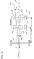
- the antennae 14a and 14b are shown disposed on the vehicle centerline 31.
- the fuzzy logic program performs the calculations described hereinbelow.
- the antenna comprising components 14a and 14b, is the basic unit of the wire guidance system. Its function is to determine the lateral position of the guidewire 26 relative to the centerline 31 of the vehicle, not shown, at the antenna location. Each antenna 14a and 14b operates independently of any other antenna in determining the lateral position of the guidewire 26. The outputs of different antennas can then be combined to provide additional position information, such as heading angle, as described in the aforementioned patent no. 4,307,329 (hereinafter Taylor).
- each antenna 14a and 14b comprises three independent channels: a nearwire channel 14a2, 14b2, respectively, and two guidance channels 14a1, 14a3 and 14b1, 14b3, respectively.
- the nearwire channel 14a2 is used to measure the amplitude of the signal from the guidewire 26. This information is used in two ways: to determine if the guidewire signals are of sufficient strength for proper operation, as discussed in the Taylor patent; and, additionally, to adjust the output of the guidance channels 14a1, 14a3 to correct for varying signal levels.
- AGC automatic gain control
- the guidance channels 14a1, 14a3 are used together to determine the lateral position of the guidewire 26 as described in the Taylor patent. Typically the output of one channel (say, 14a1) is subtracted from the output of the other channel (14a3) and then the difference is scaled to represent lateral guidewire position. In the present device, this differencing is performed by a microprocessor unit 12a in the steering controller 12. Microprocessor 12a includes a multiplexed input A/D converter 12a' for receiving signals from each antenna channel.
- Differencing has a disadvantage in that its value is proportional to the amplitude of the signal received from the guidewire 26. Thus, if the amplitude of the wire signal decreases to zero, the difference will also decrease to zero.
- automatic gain control is applied in order to prevent the amplitude of the difference signal from depending on signal strength from the guidewire 26.
- This ratio is calculated independently for each antenna, 14a and 14b. Additionally, the magnitude of this ratio is constrained to a value of between .7 and 5 in order to prevent the magnification of noise signals.
- the differenced output of the guidance coils at each antenna (say 14a) are then multiplied by the Relative Signal Ratio for that antenna 14a in order to make the differences independent of the amplitude of received signal.
- Each of the antenna channels has the same basic structure.
- the signal from the guidewire 26 is received by each channel (say 14a1) using an antenna coil 14a1' and the received signal is amplified by an amplifier 14a1'' for transmission to the steering controller 12.
- the amplifiers 14a1'', 14a2'', 14a3'' are provided with sixteen individual gain selections set in linearly spaced steps in order to advantageously provide for adapting to a large range of signals from the guidewire 26. This scheme is used in conjunction with the aforementioned AGC algorithm to extend the operating range of the antennae 14a, 14b.
- Selection of a particular gain value is controlled by the microprocessor 12a in the steering controller 12 using four digital control lines 12' and 12'', respectively for each antenna 14a and 14b.
- the gain of each antenna 14a, 14b can be set independently in order to allow compensation for reduced or increased signal conditions caused by locating the antenna at different heights and/or in proximity to objects in the vehicle frame which cause distortion of the magnetic field about the guidewire 26. These gain selections are changed as part of the process of learning the characteristics of the guidewire 26, described in greater detail hereinbelow.
- the value of gain selected is chosen in order to operate the signal channel in an optimum manner, so it will have the maximum amplitude signals possible without saturating or clipping.
- the antenna coils 14a1', 14a2', 14a3' are located and oriented in a vertical plane in order to provide maximum immunity to noise signals generated by sources other than the guidewire 26.
- the guidance coils 14a1', 14a2', 14a3' are located so as to straddle the guidewire 26, as shown in FIGURE 3.
- the outputs of these coils 14a1', 14a2', 14a3' are arranged so as to be in phase, even though they are independent channels, in order to provide maximum noise immunity. Since the guidewire 26 position is determined by subtracting two channels (14a1 from 14a3, for example), any common-mode noise received is cancelled out.
- the nearwire antenna coil consists of a single coil located at the center of the antenna.
- this nearwire antenna coil 14a2' actually consists of two separate antenna coils (shown as one in the FIGURE) which are wired together in series.
- One of the two antenna coils 14a2' is located on each side of the guidewire 26 when the antenna 14a is centered thereover, in order to extract additional benefits from the application of the automatic gain control.
- Automatic gain control cannot be applied to the nearwire channel in the Taylor patent because the output of the nearwire channel would then cause severe distortion in the displacement calculation.
- the two coils comprising the nearwire antenna 14a2 are used together to provide a relatively constant output over a range of antenna displacement in order to prevent the described distortion.
- the automatic gain control then properly responds only to signal level variations.
- the operation of the AGC algorithm is additionally enhanced in the present invention by carefully arranging the actual geometry between the guidance 14a1, 14a3 and nearwire 14a2 antennae.
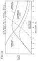
- the differenced output of the guidance antenna coils 14a1', 14a3' is generally quite linear between the coils, but peaks when either coil is directly over the guidewire 26 and then quickly falls off to zero. This relationship is shown in FIGURE 4, labeled “Uncorrected Displacement” and limits the useful range of the antenna to its physical width.
- the output of the nearwire antenna 14a2 is at a maximum when the antenna 14a is centered over the guidewire 26. It then falls off to zero as the displacement is increased. This relationship is shown in FIGURE 4, labeled "Normalized Nearwire".
- the nearwire antenna 14a2 is designed to have a relatively constant output over the range where the differenced output of the guidance channels is linear (approximately between 0 and 2 inches on FIGURE 4). Nearwire antennae output then begins to fall off at a rate approximately proportional to the rate at which the differenced output decreases from a linear output.
- the normalized nearwire output is a mirror image of the Uncorrected Displacement Error shown in FIGURE 4. This relationship causes the automatic gain control algorithm to advantageously extend the operating range of the differenced output of the guidance channels 14a1, 14a3. This relationship is shown as "Corrected Displacement" on FIGURE 4. Since the antenna range is extended by this technique, a much smaller antenna with the same range as that described by the Taylor patent can be constructed.
- United States Patent No. 3,993,156 issued to Rubel, describes an antenna coil arrangement and algorithm for providing extended operating range.
- the patented device employs two horizontally oriented coils for measuring displacement and two substantially vertical coils oriented in a plane approximately 20 degrees from vertical.
- This antenna is unable to reject common mode noise signals due to its horizontally-oriented guidance coils.
- construction is relatively expensive, due to its required concentric coils at specific angles.
- the signals from the antennae 14a and 14b are sent to a signal processing or filter card 13.
- This card 13 processes each antenna signal separately by filtering the signals using bandpass filters 13a, ..., 13f and converting the signals to DC signals referenced to ground. These signals are then converted to digital signals using the analog to digital (A/D) converter 12a' in the microprocessor 12a.
- A/D analog to digital
- Noise rejection of the antennae 14a, 14b is an important aspect of the invention, but additional measures are employed as well.
- the DC output of all channels 14a1, ..., 14b3 is fed simultaneously to respective sample and hold devices 13m, ..., 13r, which freeze all channel outputs at the same moment in order to maximize common-mode noise rejection.
- the antennae 14a and 14b are broadband receivers, by design, in order to allow reception of a variety of guidewire signals.
- the invention employs filters 13a, ..., 13f of the switched capacitor type which are digitally programmable. In the preferred embodiment, these filters 13a, ..., 13f are manufactured by Maxim Corp. as part number MAX261. These filters 13a, ..., 13f are programmed for a predetermined center frequency by application of a sampling clock, not shown, generated by an oscillator 13s and two divide-by-two (ö2) registers on the filter card 13 and by a 6-bit digital word 13t generated by the microprocessor 12a.
- a sampling clock not shown, generated by an oscillator 13s and two divide-by-two (ö2) registers on the filter card 13 and by a 6-bit digital word 13t generated by the microprocessor 12a.
- the sampling clock can be changed to three different values by the steering controller microprocessor 12a in order to extend the operating range of the bandpass filters 13a, ..., 13f.
- the 6-bit digital word 13t allows changing of the center frequency in 1% logarithmic steps.
- the combination of the 6-bit digital word 13t and selectable sampling clocks allow the microprocessor 12a to sweep the filter center frequency in order to find the frequency of the guidewire 26, as described in greater detail hereinbelow with reference to FIGURES 5a and 5b.
- the present invention is capable of bidirectional travel on a straight guidewire 26. It is also capable of automatically acquiring guidewire 26 in two ways.
- the operator may drive the vehicle until it is oriented substantially over the guidewire 26 and then move the AUTO/MANUAL switch 9 to the automatic position, causing the system to assume steering and align the vehicle with the guidewire 26.
- the operator may move the AUTO/MANUAL switch 9 to AUTOMATIC prior to being in proximity to the guidewire 26.
- the system will then assume steering only when one and/or both of the antennae 14a and 14b are in proximity to the guidewire 26 such that sufficient signal is received.
- the vehicle will then be automatically steered so as to align it with the guidewire 26.
- the antennae 14a and 14b shown in FIGURES 1 and 3, previously described, are used together in some cases, and are used individually in other cases. Normal bidirectional operation on the guidewire 26 uses both antennae 14a and 14b together. Alternatively said antennae are used individually during acquisition of the guidewire 26 and/or in the event that one antenna 14a and/or 14b fails while both are being used together. The operation of the antennae 14a and 14b changes during acquisition of the guidewire 26 from individual operation to dual operation as soon as the minimum required signal is received in each antenna 14a and 14b.
- a disadvantage of the Taylor arrangement is the inability to move the antennae away from the fixed axle of the vehicle while maintaining bidirectional operation. Moving the antennae away from the fixed axle is an advantage in that the antennae can be located on the vehicle more easily and can also be moved to a location which provides additional protection from damage.
- Operation of the present invention provides for the use of both antennae 14a and 14b together, as described hereinafter.
- LTCP and LLCP may be positive or negative as dictated by operational and physical needs of the vehicle.
- the vehicle's distance from the wire should be calculated at the load axle 29, rather than at the sensor location. If it is not calculated at the load axle 29, then the DFW signal will favor one direction of travel over the other. Since it is more likely for designers to mount the sensor on the tractor end, the tractor's first travel will be aided and forks-first travel will be impeded, if DFW is not calculated at the load axle. This is very undesirable, since, due to vehicle geometry, it is more difficult to steer a vehicle in the forks-first direction.
- the steer manager 16 accepts the industry standard frequencies 5.2 KHz or 6.25 KHz as configurable guidance frequencies. This information is transmitted to the steer manager 16 via the network communications bus 17 during initialization of the system.
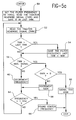
- FIGURE 5a describes the process used for determining the guidewire frequency.
- First the programmable filters' center frequency and gain are set to their maximum values, step 50.
- the Tractor Near Wire (TNW) signal is continuously monitored, step 52.
- a trap for maximum signal of TNW and the current center frequency setting is performed, shown generally at step 54. If, during this process, the TNW signal becomes saturated, step 56, the gain is reduced, step 58. If the gain is at its minimum, then the guidewire signal is too strong for proper wire guidance, step 60, and the learning process is aborted. Otherwise, the center frequency is then decreased, step 62, to a minimum allowable frequency, step 64. After the full frequency range has been scanned, the center frequency has been found, step 66.
- TNW Tractor Near Wire
- the gain of the antennae 14a and 14b must be adjusted. This is accomplished using the process described in FIGURE 5b.
- the filters are set to the aforementioned center frequency and the antennae gains are again set to their maximum limits, step 68.
- the Tractor Nearwire (TNW) and Load Nearwire (LNW) signals are continuously monitored, step 70. If the TNW signal is greater than its maximum usable voltage, step 72, the TNW gain is reduced, step 74. If the TNW signal is less than the maximum usable voltage, step 72, and also greater than its minimum usable voltage, step 76, then the tractor antennae gain has been found, step 78. However, if the TNW signal is less than the minimum usable voltage, step 76, then the guidewire signal is too weak for proper wire guidance, step 80.
- TNW Tractor Nearwire
- LNW Load Nearwire
- step 82 After both antennae 14a, 14b have had their gains set, the learning process is complete, step 82.
- Management of the steering system requires information from the vehicle, such as the position of the auto/manual switch, not shown, vehicular speed, and travel direction.
- the steer manager 16 has access to this information through its interface to the network communication bus 17. This interface allows all of the vehicular computers (not shown) to work together as a single, seamless unit; it also allows the steering information to be registered directly on the operator's displays (not shown).
- the steer manager 16 also has its own interface devices for the vehicle's steering components.
- An amplifier 28 within the steer manager 16 directly drives the steering motor 15, as shown.
- the position of the drive unit 18 is determined by monitoring the signals from a feedback device 27 connected to the drive unit 18.
- the commands to the steering motor 15 are derived using fuzzy logic from the position error (actual position minus requested position) and the rate of change of the position error.
- the steer manager 16 determines the appropriate time to switch from manual to automatic steering and vice-versa. If the AUTO/MANUAL switch 9 is in the manual position, the input from the operator's steering tiller 19 is generally used. Exceptions are made only when an error condition prevents manual steering.
- the AUTO/MANUAL switch 9 is provided for operating the vehicle in either mode.
- the signals from the respective wire guidance antennae 14a and 14b are used to steer the vehicle when certain conditions are met.
- Automatic steering begins only when a guidewire 26 of the appropriate frequency and signal strength is detected.
- Ability to acquire wire is limited by vehicle physical features such as mass, steer rate, traction, and response time. If the sensor overshoots the guidewire 26 due to excessive speed and/or an acquisition angle outside of a nominal range, the steering immediately reverts to the manual mode. If the guidewire signal disappears while the vehicle is acquiring it, or while it is locked thereonto, the steering again immediately reverts to the manual mode. Steering also reverts to manual mode under any conditions that prevent proper wire guidance operation, such as antenna or guidewire failure.
- the steer manager 16 interacts with the vehicle through its interface to the network communications bus 17, as aforementioned.
- the steer manager 16 reads and writes to the bus 17 in a timely manner to provide sufficient updates of information throughout the vehicle.
- the steer manager 16 also detects any failure of the communications network and/or the information provided by the bus 17, taking necessary and appropriate actions.
- the steer manager 16 provides information about the steering system (such as drive unit position, steering status, error conditions, and maintenance mode information) to the system controller 11.
- the steer manager 16 detects any condition of poor steering function performance, due to either long delays in responding to commands and/or limited maximum rotation rates. If the steer manager 16 determines that the vehicle has deviated from the wire by 3° of heading angle or 3" of distance from wire, a message is sent to the system controller 11.
- the limits of 3° and 3" are, of course, arbitrary, and can be configurable by the system controller to lower values, if desired.
- Proper wire guidance includes stopping the vehicle due to excessive distance from wire and/or angular deviation. Steering does not revert to manual mode under this condition, unless the antenna range is exceeded.
- the steer manager 16 also provides a fail guidance feature wherein the drive unit is turned to a straight-ahead direction and actively held there. Both the operator's steering tiller 19 and the wire guidance signals are ignored. This feature is used to reduce stress on the traction system and scuffing of the drive tire, not shown.
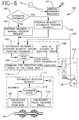
- FIGURE 6 a flow chart 100 of the logic program of this invention is illustrated.
- the drive unit 18 (FIGURE 2) is automatically set to the straight-ahead position.
- the steer manager 16 broadcasts a message informing other systems of its readiness.
- the steer manager 16 periodically broadcasts the actual position of the drive unit 18.
- the tiller 19 provides a manual position request 101, shown as signal "B".
- a decision block 102 of the logic program determines whether the system AUTO/MANUAL switch 9 is in the AUTOMATIC mode. If the system is on automatic control, step 103, the position request is equal to the automated position request, as indicated by the signal shown as "A". The distance from wire is calculated, step 112, and the vehicle heading angle is calculated, step 114, using the formula in FIGURE 3. The DFW and ⁇ (heading angle) are used to calculate the automatic position request "A", step 115, in accordance with the following equations:
- Automated Position Request K 1 * DFW ⁇ K 2 * ⁇ where K 1 and K 2 are scaling constants.
- Automated Position Request K 3 * DTCP where K 3 is a scaling constant.
- step 112 or step 114 a signal is provided to the system controller 11 informing it of the aforementioned condition.
- step 102 the position request is set equal to the manual position request, step 104.
- Either automated position request signal "A” or manned position request signal “B” is fed to block 105.
- a position feedback signal 107 is also fed to block 105 from the steer unit 106.
- Block 105 determines the error between the requested signal and the feedback position.
- An appropriate signal is generated and the rate of change of the steering position error is calculated, step 108.
- Both determinations from blocks 105 and 108 are fed to a fuzzy logic routine 109, developed using the fuzzy logic package, as aforementioned.
- the fuzzy logic routine 109 provides a signal which is used to produce a command for direction and speed, step 110, that is sent to the steer motor 15, as shown.
Landscapes
- Engineering & Computer Science (AREA)
- Physics & Mathematics (AREA)
- General Physics & Mathematics (AREA)
- Aviation & Aerospace Engineering (AREA)
- Radar, Positioning & Navigation (AREA)
- Remote Sensing (AREA)
- Automation & Control Theory (AREA)
- Transportation (AREA)
- Mechanical Engineering (AREA)
- Combustion & Propulsion (AREA)
- Chemical & Material Sciences (AREA)
- Electromagnetism (AREA)
- Control Of Position, Course, Altitude, Or Attitude Of Moving Bodies (AREA)
Description
- The present invention pertains to guidewire controls for manned material handling vehicles and, more particularly, to a universal guidewire fuzzy control system for manned material handling vehicles that is capable of adapting to and learning the different frequencies and amplitudes of diverse guidewire systems.
- Unmanned vehicles have heretofore been guided through a warehouse or other storage facility by guidewire control systems. Fuzzy logic can also be used to control the speed and direction of unmanned vehicles, as is illustrated in United States Patent No. 5,218,542 (issued to Endo et al on June 8, 1993).
- Many manned material handling vehicles which may be of a type designed for order picking can be alternatively controlled by a wire guidance system. Such additional control is a valuable operative feature.
- The use of pairs of coils disposed on the vehicle centerline, in order to generate an error signal indicative of vehicle deviation from the embedded or buried wire, is also well known, as illustrated in United States Patent No. 4,307,329 (issued to Taylor on December 22, 1981).
- The
DE 30 37 221 C1 discloses a manned material handling vehicle that is operative in either a manual or an automatic wire guidance mode, the vehicle comprising means for generating a position request signal in either said manual mode or said automatic wire guidance mode, a steer unit generating a feedback signal, and steering control means processing said feedback signal from said steer unit along with said position request signal generated in either mode of operation and speed, which generated command is fed to said steer unit to guide said material handling vehicle. - The
EP 0 138 097 A1 discloses steering control means with center frequency adjustment for a wire guided vehicle which is able to operate on different wire systems. - Designing a manned vehicle for wire guidance operations continues to pose several problems. Each warehouse facility that has installed guidewire controls for guided vehicles operates the controls at different wire frequencies and amplitudes that are designed for its own distinct wire-guided system. Any mass-produced (non-customized) material handling vehicle must, therefore, have the capability of recognizing and responding to the different frequencies and amplitudes of warehouse wire guidance systems. Manned material handling vehicles must have the capability of automatically switching to manual control when the wire guidance control is interrupted or becomes disabled.
- It would be advantageous to provide a logic control structure for adapting to the different frequencies and amplitudes of the various wire guidance systems.
- It would also be advantageous for such logic to allow for automatic switching from wire guidance to manual control when guidance signals are inadequate to properly guide the vehicle.
- The logic of the present invention operates in a learning mode, wherein the logic learns the parameters of the guidance system, and is thereafter capable of sufficiently operating under wire guidance control. The operator of the manned vehicle situates the vehicle over the guidance wire so that antennae within the vehicle can sense the signal from the guidewire. The antennae system is automatically normalized to adapt the vehicle to any signal level or frequency.
- The vehicle is steered by means of a DC steer motor that forms part of the steer wheel control system. Fuzzy logic is used to control the position of the motor. The heading angle drive unit position is automatically and continuously updated as a function of actual vehicle position measurements, so that the vehicle does not overshoot. Should the wire signal be lost, the material handling vehicle will automatically revert to the manual steering mode, and the brake will be applied.
- In accordance with the present invention, there is provided a method to be used with a material handling vehicle that is operative in an automatic wire guidance mode, the vehicle being used with a plurality of automatic wire guidance systems, each system transmitting guidance signals having a frequency and amplitude characteristic of the system, the guidance signals being used to guide the vehicle, the vehicle including a steering control means and a signal sensor, the method automatically calibrating the steering control means so that it is responsive to guidance signals from one of said guidance systems, said one of the guidance systems being a system with which the vehicle is to be used, the method comprising the steps of:
- sensing the guidance signals corresponding to the one of the guidance systems;
- processing the sensed signal to ascertain the characteristic amplitude and frequency of the guidance signals; and
- adjusting the steering control means so that the steering control means is responsive to signals having substantially the characteristic amplitude and frequency of the guidance signals.
- Further there is provided an apparatus to be used with a material handling vehicle that is operative in an automatic wire guidance mode, the vehicle being used with a plurality of automatic wire guidance systems, each system transmitting guidance signals having a frequency and amplitude characteristic of the system, the guidance signals being used to guide the vehicle, the vehicle including a steering control means, the apparatus automatically calibrating the steering control means so that the steering control means is responsive to guidance signals from one of said guidance systems, said one of the guidance systems being a system with which the vehicle is to be used, the apparatus comprising:
- a sensor for sensing the guidance signals corresponding to the one of the guidance systems;
- a processor for processing the sensed signals to ascertain the characteristic amplitude and frequency of the guidance signals; and
- means for adjusting the steering control means so that the steering control means is responsive to signals having substantially the characteristic amplitude and frequency of the guidance signals.
- A complete understanding of the present invention may be obtained by reference to the accompanying drawings, when considered in conjunction with the subsequent detailed description, in which:
- FIGURE 1 is a schematic diagram of the control system of the invention;
- FIGURE 2 is a schematic diagram of the steering management control system of the inventive system shown in FIGURE 1;
- FIGURE 3 is a schematic diagram of the antenna's layout for guiding a material handling vehicle;
- FIGURE 4 is a graph depicting measured displacement and corrected displacement signals for each antenna;
- FIGURES 5a and 5b are flow charts of the process used, respectively, to determine frequency of the guide wire identified by the vehicle and to determine appropriate antenna gains; and
- FIGURE 6 is a flow chart and schematic diagram of the steering mechanism, in accordance with the steering management control system illustrated in FIGURE 2.
- Generally speaking, the invention pertains to an electronic steering system for operating material handling vehicles in either a manual or an otherwise guided mode. This steering system comprises a logic program that adapts to, and learns, the frequencies and amplitudes of any particular guidewire. Failure to sense the guidewire signal will cause the steering control to switch to manual operation. This steering system employs fuzzy logic for controlling the steering unit.
- Now referring to FIGURES 1 and 2, schematic diagrams of the
control system 10 of this invention are illustrated. Thecontrol system 10 comprises asystem controller 11 that communicates with asteering controller 12 via acommunications bus 17. Thesystem controller 11 is responsive to the manual direction signal provided by asteering tiller 19, an AUTO/MANUAL switch 9, and vehicle speed, as represented by atraction encoder 30. A steer manager 16 (FIGURE 2) is programmed with fuzzy logic; thesteer manager 16 controls the operational modes (i.e., either a manual or a wire guidance mode) of thesteering controller 12.Steering controller 12 has two basic tasks, to wit, managing the overall operation of the steering system and positioning the drive unit (steer motor 15 and steer wheel or drive unit 18), based on commands from either the operator'ssteering tiller 19 or the information provided by wire guidance (antennae - The logic program of the
steer manager 16 also provides for the configuration of several system variables which allow the operation of the vehicle to be customized for or by the user, not shown. - A positioning routine in the fuzzy logic program utilizes a signal denoting where the
drive unit 18 is to be positioned; it then determines where thedrive unit 18 is actually positioned and generates the necessary commands to move it to the desired position. The fuzzy logic program is developed using the fuzzy logic package FidVersion 1.03, from Aptronics Corp.
- The
steering controller 12 receives signals from the pair ofwire guidance antennae steering motor 15, and hence the attitude of the vehicle which may be of a type designed for order picking (not shown) via thesteer wheel 18. - Referring now also to FIGURE 3, the
antennae guidewire 26. Theantennae vehicle centerline 31. In order to guide the vehicle, the fuzzy logic program performs the calculations described hereinbelow. - The antenna, comprising
components guidewire 26 relative to thecenterline 31 of the vehicle, not shown, at the antenna location. Eachantenna guidewire 26. The outputs of different antennas can then be combined to provide additional position information, such as heading angle, as described in the aforementioned patent no. 4,307,329 (hereinafter Taylor). - Referring again to FIGURE 1, each
antenna antenna 14a and components associated therewith will be described in detail, sinceantenna 14b operates identically. The nearwire channel 14a2 is used to measure the amplitude of the signal from theguidewire 26. This information is used in two ways: to determine if the guidewire signals are of sufficient strength for proper operation, as discussed in the Taylor patent; and, additionally, to adjust the output of the guidance channels 14a1, 14a3 to correct for varying signal levels. This second application is commonly referred to as automatic gain control (AGC). - The guidance channels 14a1, 14a3 are used together to determine the lateral position of the
guidewire 26 as described in the Taylor patent. Typically the output of one channel (say, 14a1) is subtracted from the output of the other channel (14a3) and then the difference is scaled to represent lateral guidewire position. In the present device, this differencing is performed by amicroprocessor unit 12a in thesteering controller 12.Microprocessor 12a includes a multiplexed input A/D converter 12a' for receiving signals from each antenna channel. - Differencing has a disadvantage in that its value is proportional to the amplitude of the signal received from the
guidewire 26. Thus, if the amplitude of the wire signal decreases to zero, the difference will also decrease to zero. In the present device, automatic gain control is applied in order to prevent the amplitude of the difference signal from depending on signal strength from theguidewire 26. - Operation of the automatic gain control consists of an AGC algorithm that measures the amplitude of the received signal in the nearwire channel 14a2 independently in each antenna, and then compares the measured values against a set reference value in the form of ratios:

- This ratio is calculated independently for each antenna, 14a and 14b. Additionally, the magnitude of this ratio is constrained to a value of between .7 and 5 in order to prevent the magnification of noise signals. The differenced output of the guidance coils at each antenna (say 14a) are then multiplied by the Relative Signal Ratio for that
antenna 14a in order to make the differences independent of the amplitude of received signal. These ratios and multiplications are performed bymicroprocessor 12a in thesteering controller 12. - Each of the antenna channels has the same basic structure. The signal from the
guidewire 26 is received by each channel (say 14a1) using an antenna coil 14a1' and the received signal is amplified by an amplifier 14a1'' for transmission to thesteering controller 12. The amplifiers 14a1'', 14a2'', 14a3'' are provided with sixteen individual gain selections set in linearly spaced steps in order to advantageously provide for adapting to a large range of signals from theguidewire 26. This scheme is used in conjunction with the aforementioned AGC algorithm to extend the operating range of theantennae - Selection of a particular gain value is controlled by the
microprocessor 12a in thesteering controller 12 using fourdigital control lines antenna antenna guidewire 26. These gain selections are changed as part of the process of learning the characteristics of theguidewire 26, described in greater detail hereinbelow. The value of gain selected is chosen in order to operate the signal channel in an optimum manner, so it will have the maximum amplitude signals possible without saturating or clipping. - The antenna coils 14a1', 14a2', 14a3' are located and oriented in a vertical plane in order to provide maximum immunity to noise signals generated by sources other than the
guidewire 26. The guidance coils 14a1', 14a2', 14a3' are located so as to straddle theguidewire 26, as shown in FIGURE 3. The outputs of these coils 14a1', 14a2', 14a3' are arranged so as to be in phase, even though they are independent channels, in order to provide maximum noise immunity. Since theguidewire 26 position is determined by subtracting two channels (14a1 from 14a3, for example), any common-mode noise received is cancelled out. - In the Taylor patent, the nearwire antenna coil consists of a single coil located at the center of the antenna. In the present device, however, this nearwire antenna coil 14a2' actually consists of two separate antenna coils (shown as one in the FIGURE) which are wired together in series. One of the two antenna coils 14a2' is located on each side of the
guidewire 26 when theantenna 14a is centered thereover, in order to extract additional benefits from the application of the automatic gain control. - Automatic gain control cannot be applied to the nearwire channel in the Taylor patent because the output of the nearwire channel would then cause severe distortion in the displacement calculation. The two coils comprising the nearwire antenna 14a2 are used together to provide a relatively constant output over a range of antenna displacement in order to prevent the described distortion. The automatic gain control then properly responds only to signal level variations.
- The operation of the AGC algorithm is additionally enhanced in the present invention by carefully arranging the actual geometry between the guidance 14a1, 14a3 and nearwire 14a2 antennae. The differenced output of the guidance antenna coils 14a1', 14a3', is generally quite linear between the coils, but peaks when either coil is directly over the
guidewire 26 and then quickly falls off to zero. This relationship is shown in FIGURE 4, labeled "Uncorrected Displacement" and limits the useful range of the antenna to its physical width. In a similar fashion, the output of the nearwire antenna 14a2 is at a maximum when theantenna 14a is centered over theguidewire 26. It then falls off to zero as the displacement is increased. This relationship is shown in FIGURE 4, labeled "Normalized Nearwire". - The nearwire antenna 14a2 is designed to have a relatively constant output over the range where the differenced output of the guidance channels is linear (approximately between 0 and 2 inches on FIGURE 4). Nearwire antennae output then begins to fall off at a rate approximately proportional to the rate at which the differenced output decreases from a linear output. In other words, the normalized nearwire output is a mirror image of the Uncorrected Displacement Error shown in FIGURE 4. This relationship causes the automatic gain control algorithm to advantageously extend the operating range of the differenced output of the guidance channels 14a1, 14a3. This relationship is shown as "Corrected Displacement" on FIGURE 4. Since the antenna range is extended by this technique, a much smaller antenna with the same range as that described by the Taylor patent can be constructed.
- United States Patent No. 3,993,156, issued to Rubel, describes an antenna coil arrangement and algorithm for providing extended operating range. The patented device employs two horizontally oriented coils for measuring displacement and two substantially vertical coils oriented in a plane approximately 20 degrees from vertical. This antenna is unable to reject common mode noise signals due to its horizontally-oriented guidance coils. Moreover, construction is relatively expensive, due to its required concentric coils at specific angles.
- Referring again to FIGURE 1, the signals from the
antennae filter card 13. Thiscard 13 processes each antenna signal separately by filtering the signals usingbandpass filters 13a, ..., 13f and converting the signals to DC signals referenced to ground. These signals are then converted to digital signals using the analog to digital (A/D)converter 12a' in themicroprocessor 12a. - Noise rejection of the
antennae devices 13m, ..., 13r, which freeze all channel outputs at the same moment in order to maximize common-mode noise rejection. - Filtering of the signals is important to remove unwanted signals generated by external devices such as power lines, lighting, etc. The
antennae filters 13a, ..., 13f of the switched capacitor type which are digitally programmable. In the preferred embodiment, thesefilters 13a, ..., 13f are manufactured by Maxim Corp. as part number MAX261. Thesefilters 13a, ..., 13f are programmed for a predetermined center frequency by application of a sampling clock, not shown, generated by an oscillator 13s and two divide-by-two (ö2) registers on thefilter card 13 and by a 6-bitdigital word 13t generated by themicroprocessor 12a. The sampling clock can be changed to three different values by thesteering controller microprocessor 12a in order to extend the operating range of thebandpass filters 13a, ..., 13f. The 6-bitdigital word 13t allows changing of the center frequency in 1% logarithmic steps. The combination of the 6-bitdigital word 13t and selectable sampling clocks allow themicroprocessor 12a to sweep the filter center frequency in order to find the frequency of theguidewire 26, as described in greater detail hereinbelow with reference to FIGURES 5a and 5b. - The present invention is capable of bidirectional travel on a
straight guidewire 26. It is also capable of automatically acquiringguidewire 26 in two ways. The operator may drive the vehicle until it is oriented substantially over theguidewire 26 and then move the AUTO/MANUAL switch 9 to the automatic position, causing the system to assume steering and align the vehicle with theguidewire 26. Alternately, the operator may move the AUTO/MANUAL switch 9 to AUTOMATIC prior to being in proximity to theguidewire 26. The system will then assume steering only when one and/or both of theantennae guidewire 26 such that sufficient signal is received. The vehicle will then be automatically steered so as to align it with theguidewire 26. - The
antennae guidewire 26 uses bothantennae guidewire 26 and/or in the event that oneantenna 14a and/or 14b fails while both are being used together. The operation of theantennae antenna - Use of the
antennae - An additional disadvantage of the Taylor design is the reliance on fixed antenna dimensions whereas flexible dimensions can better provide for the needs of a plurality of different vehicles.
- Operation of the present invention provides for the use of both
antennae - The calculations for the heading angle (ψ) should remain the same as that in existing systems:

- DLCP
- is the corrected displacement at the load measured coil pair
- DTCP
- is the corrected displacement at the tractor measured coil pair
- K_ψ
- is a scaling factor to yield output in degrees.
- LTCP
- is the length from load axle to tractor coil pair
- LLCP
- is the length from load axle to load coil pair
- K_DFW
- is a distance from wire scaling constant, determined by geometry and gain of amplifiers 14a1'' through 14a3''.
- The dimensions LTCP and LLCP may be positive or negative as dictated by operational and physical needs of the vehicle.
- The vehicle's distance from the wire should be calculated at the
load axle 29, rather than at the sensor location. If it is not calculated at theload axle 29, then the DFW signal will favor one direction of travel over the other. Since it is more likely for designers to mount the sensor on the tractor end, the tractor's first travel will be aided and forks-first travel will be impeded, if DFW is not calculated at the load axle. This is very undesirable, since, due to vehicle geometry, it is more difficult to steer a vehicle in the forks-first direction. - To calculate the distance from wire (displacement) at the
load axle 29, displacement at one coil pair and the vehicle heading angle must be known.
- The distance from wire (DFW) and heading angle (ψ) signals are then combined (FIGURE 6) as described in Taylor.
- The
steer manager 16 accepts the industry standard frequencies 5.2 KHz or 6.25 KHz as configurable guidance frequencies. This information is transmitted to thesteer manager 16 via thenetwork communications bus 17 during initialization of the system. - FIGURE 5a describes the process used for determining the guidewire frequency. First the programmable filters' center frequency and gain are set to their maximum values,
step 50. The Tractor Near Wire (TNW) signal is continuously monitored,step 52. A trap for maximum signal of TNW and the current center frequency setting is performed, shown generally atstep 54. If, during this process, the TNW signal becomes saturated,step 56, the gain is reduced,step 58. If the gain is at its minimum, then the guidewire signal is too strong for proper wire guidance,step 60, and the learning process is aborted. Otherwise, the center frequency is then decreased,step 62, to a minimum allowable frequency,step 64. After the full frequency range has been scanned, the center frequency has been found,step 66. - After determining the center frequency (FIGURE 5a), the gain of the
antennae step 68. The Tractor Nearwire (TNW) and Load Nearwire (LNW) signals are continuously monitored,step 70. If the TNW signal is greater than its maximum usable voltage,step 72, the TNW gain is reduced,step 74. If the TNW signal is less than the maximum usable voltage,step 72, and also greater than its minimum usable voltage,step 76, then the tractor antennae gain has been found,step 78. However, if the TNW signal is less than the minimum usable voltage,step 76, then the guidewire signal is too weak for proper wire guidance,step 80. - The same process is performed on the LNW signal, as indicated by steps 72' - 80' on FIGURE 5b.
- After both
antennae step 82. - Management of the steering system requires information from the vehicle, such as the position of the auto/manual switch, not shown, vehicular speed, and travel direction. The
steer manager 16 has access to this information through its interface to thenetwork communication bus 17. This interface allows all of the vehicular computers (not shown) to work together as a single, seamless unit; it also allows the steering information to be registered directly on the operator's displays (not shown). - The
steer manager 16 also has its own interface devices for the vehicle's steering components. Anamplifier 28 within thesteer manager 16 directly drives thesteering motor 15, as shown. The position of thedrive unit 18 is determined by monitoring the signals from afeedback device 27 connected to thedrive unit 18. The commands to thesteering motor 15 are derived using fuzzy logic from the position error (actual position minus requested position) and the rate of change of the position error. - The
steer manager 16 determines the appropriate time to switch from manual to automatic steering and vice-versa. If the AUTO/MANUAL switch 9 is in the manual position, the input from the operator'ssteering tiller 19 is generally used. Exceptions are made only when an error condition prevents manual steering. - The AUTO/
MANUAL switch 9 is provided for operating the vehicle in either mode. In the "automatic" position, the signals from the respectivewire guidance antennae guidewire 26 of the appropriate frequency and signal strength is detected. Ability to acquire wire is limited by vehicle physical features such as mass, steer rate, traction, and response time. If the sensor overshoots theguidewire 26 due to excessive speed and/or an acquisition angle outside of a nominal range, the steering immediately reverts to the manual mode. If the guidewire signal disappears while the vehicle is acquiring it, or while it is locked thereonto, the steering again immediately reverts to the manual mode. Steering also reverts to manual mode under any conditions that prevent proper wire guidance operation, such as antenna or guidewire failure. - The
steer manager 16 interacts with the vehicle through its interface to thenetwork communications bus 17, as aforementioned. Thesteer manager 16 reads and writes to thebus 17 in a timely manner to provide sufficient updates of information throughout the vehicle. Thesteer manager 16 also detects any failure of the communications network and/or the information provided by thebus 17, taking necessary and appropriate actions. - The
steer manager 16 provides information about the steering system (such as drive unit position, steering status, error conditions, and maintenance mode information) to thesystem controller 11. - The
steer manager 16 detects any condition of poor steering function performance, due to either long delays in responding to commands and/or limited maximum rotation rates. If thesteer manager 16 determines that the vehicle has deviated from the wire by 3° of heading angle or 3" of distance from wire, a message is sent to thesystem controller 11. The limits of 3° and 3" are, of course, arbitrary, and can be configurable by the system controller to lower values, if desired. - Proper wire guidance includes stopping the vehicle due to excessive distance from wire and/or angular deviation. Steering does not revert to manual mode under this condition, unless the antenna range is exceeded.
- The
steer manager 16 also provides a fail guidance feature wherein the drive unit is turned to a straight-ahead direction and actively held there. Both the operator'ssteering tiller 19 and the wire guidance signals are ignored. This feature is used to reduce stress on the traction system and scuffing of the drive tire, not shown. - Now referring to FIGURE 6, a
flow chart 100 of the logic program of this invention is illustrated. When the vehicle is first powered-up and the "deadman", not shown, has been activated, the drive unit 18 (FIGURE 2) is automatically set to the straight-ahead position. Thesteer manager 16 broadcasts a message informing other systems of its readiness. Thesteer manager 16 periodically broadcasts the actual position of thedrive unit 18. In the manual mode of operation, thetiller 19 provides amanual position request 101, shown as signal "B". - A
decision block 102 of the logic program determines whether the system AUTO/MANUAL switch 9 is in the AUTOMATIC mode. If the system is on automatic control,step 103, the position request is equal to the automated position request, as indicated by the signal shown as "A". The distance from wire is calculated,step 112, and the vehicle heading angle is calculated,step 114, using the formula in FIGURE 3. The DFW and ψ (heading angle) are used to calculate the automatic position request "A",step 115, in accordance with the following equations: - For two antennae:

- For one antenna (e.g., tractor antenna), when vehicle is being guided on wire:

- For one antenna (e.g., tractor antenna), when the vehicle is acquiring wire:


- K4 is a scaling constant
- ΔDFW is the difference of relative wire position over time.
- If either calculation (step 112 or step 114) is beyond the tolerance required, a signal is provided to the
system controller 11 informing it of the aforementioned condition. If the manual mode is active,step 102, the position request is set equal to the manual position request,step 104. Either automated position request signal "A" or manned position request signal "B" is fed to block 105. Aposition feedback signal 107 is also fed to block 105 from thesteer unit 106.Block 105 determines the error between the requested signal and the feedback position. An appropriate signal is generated and the rate of change of the steering position error is calculated,step 108. Both determinations fromblocks fuzzy logic routine 109, developed using the fuzzy logic package, as aforementioned. Thefuzzy logic routine 109 provides a signal which is used to produce a command for direction and speed,step 110, that is sent to thesteer motor 15, as shown. - The rule-based fuzzy logic definitions of input and output variables, along with rules used in the preferred embodiment, are shown below in the FIL language.


Claims (9)
- A method to be used with a material handling vehicle that is operative in an automatic wire guidance mode, the vehicle being used with a plurality of automatic wire guidance systems, each system transmitting guidance signals having a frequency and amplitude characteristic of the system, the guidance signals being used to guide the vehicle, the vehicle including a steering control means (16) and a signal sensor (14a, 14b), the method automatically calibrating the steering control means (16) so that it is responsive to guidance signals from one of said guidance systems, said one of the guidance systems being a system with which the vehicle is to be used, the method comprising the steps of:a) sensing (52, 70) the guidance signals corresponding to the one of the guidance systems;b) Processing (54, 56, 58, 60, 62, 64, 72, 72', 76, 78, 80, 74', 78', 76', 80') the sensed signal to ascertain the characteristic amplitude and frequency of the guidance signals; andc) adjusting (66, 78, 78') the steering control means so that the steering control means is responsive to signals having substantially the characteristic amplitude and frequency of the guidance signals.
- The method of claim 1 wherein the step of sensing includes the step of generating (52, 70) a feedback signal indicating the position of the vehicle with respect to the wire (26) of the guidance system wherein the feedback signal also comprises information indicating the amplitude and frequency of the guidance signals.
- The method of claim 1 or 2
wherein the step of processing includes the step of monitoring (52, 54, 56, 58, 62, 64) the sensed signal at each frequency within a range of possible guidance signal frequencies to identify the guidance signal frequency, the guidance signal frequency being the frequency at which the sensed signal is the strongest. - The method of claim 3
wherein the step of adjusting includes the steps of:changing (74') the amplifier gain of a variable gain amplitude amplifier of the steering control means so that amplified guidance signals have an amplitude within a steering control means range; andcalibrating (78, 78') the steering control means to be responsive to signals at substantially the guidance signal frequency. - The method of anyone of claims 1 to 4, further including the step of, prior to sensing, in a vehicle also operative in the manual mode, moving the vehicle into a position within a receiving range of said one of the guidance systems.
- An apparatus to be used with a material handling vehicle that is operative in an automatic wire guidance mode, the vehicle being used with a plurality of automatic wire guidance systems, each system transmitting guidance signals having a frequency and amplitude characteristic of the system, the guidance signals being used to guide the vehicle, vehicle including a steering control means (16), the apparatus automatically calibrating the steering control means (16) so that the steering control means is responsive to guidance signals from one of said guidance systems, said one of the guidance systems being a system with which the vehicle is to be used, the apparatus comprising:a) a sensor (14a, 14b) for sensing the guidance signals corresponding to the one of the guidance systems;b) a processor (12) for processing the sensed signals to ascertain the characteristic amplitude and frequency of the guidance signals; andc) means (12) for adjusting the steering control means (16) so that the steering control means (16) is responsive to signals having substantially the characteristic amplitude and frequency of the guidance signals.
- The apparatus of claim 6
wherein the sensor (14a, 14b) generates a feedback signal indicating the position of the vehicle with respect to the wire (26) of the guidance system wherein the feedback signal also comprises information indicating the amplitude and frequency of the guidance signals. - The apparatus of claim 6 or 7
wherein the processor (12) includes a monitor (14a, 14b, 14c) for monitoring the sensed signal at each frequency within a range of possible guidance signal frequencies to identify the guidance signal frequency, the guidance signal frequency being the frequency at which the sensed signal is the strongest. - The apparatus of claim 8
wherein the means for adjusting changes the amplifier gain of a variable gain amplitude amplifier of the steering control means so that an amplified guidance signal has an amplitude within a steering control means range and the means for adjusting calibrates the steering control means to be responsive to signals at substantially the guidance signal frequency.
Applications Claiming Priority (2)
| Application Number | Priority Date | Filing Date | Title |
|---|---|---|---|
| US15070893A | 1993-11-10 | 1993-11-10 | |
| US150708 | 1993-11-10 |
Publications (2)
| Publication Number | Publication Date |
|---|---|
| EP0658467A1 EP0658467A1 (en) | 1995-06-21 |
| EP0658467B1 true EP0658467B1 (en) | 1997-11-26 |
Family
ID=22535679
Family Applications (1)
| Application Number | Title | Priority Date | Filing Date |
|---|---|---|---|
| EP94102028A Expired - Lifetime EP0658467B1 (en) | 1993-11-10 | 1994-02-10 | Guidewire controls for a manned, material handling vehicle |
Country Status (4)
| Country | Link |
|---|---|
| US (1) | US5778327A (en) |
| EP (1) | EP0658467B1 (en) |
| CA (1) | CA2116459C (en) |
| DE (1) | DE69407024T2 (en) |
Families Citing this family (29)
| Publication number | Priority date | Publication date | Assignee | Title |
|---|---|---|---|---|
| DE19508944A1 (en) * | 1995-03-13 | 1996-09-19 | Claas Ohg | Self steering device |
| JPH1069219A (en) * | 1996-08-28 | 1998-03-10 | Honda Motor Co Ltd | Automatic traveling road and automatic traveling system |
| US5906647A (en) | 1996-09-03 | 1999-05-25 | Chrysler Corporation | Vehicle mounted guidance antenna for automated durability road (ADR) facility |
| US5906646A (en) * | 1996-12-19 | 1999-05-25 | Caterpillar Inc. | System and method for managing access to a resource shared by a plurality of mobile machines |
| US6198992B1 (en) * | 1997-10-10 | 2001-03-06 | Trimble Navigation Limited | Override for guidance control system |
| US6580990B2 (en) | 2000-08-30 | 2003-06-17 | The Raymond Corporation | Integrity check for electric steer system |
| US6445984B1 (en) | 2001-05-25 | 2002-09-03 | The Raymond Corporation | Steer control system for material handling vehicles |
| US7017689B2 (en) * | 2004-05-06 | 2006-03-28 | Crown Equipment Corporation | Electrical steering assist for material handling vehicles |
| WO2006039117A2 (en) * | 2004-09-21 | 2006-04-13 | Skyfence Inc. | Positioning system that uses signals from a point source |
| US20070239312A1 (en) * | 2006-04-10 | 2007-10-11 | Andersen Scott P | System and method for tracking inventory movement using a material handling device |
| US8762004B2 (en) * | 2006-08-03 | 2014-06-24 | Amir Khajepour | Vehicle dynamic control using pulsed active steering strategy |
| US9645968B2 (en) | 2006-09-14 | 2017-05-09 | Crown Equipment Corporation | Multiple zone sensing for materials handling vehicles |
| US8970363B2 (en) | 2006-09-14 | 2015-03-03 | Crown Equipment Corporation | Wrist/arm/hand mounted device for remotely controlling a materials handling vehicle |
| US9122276B2 (en) | 2006-09-14 | 2015-09-01 | Crown Equipment Corporation | Wearable wireless remote control device for use with a materials handling vehicle |
| US8260499B2 (en) * | 2007-05-01 | 2012-09-04 | Deere & Company | Automatic steering system and method for a work vehicle with feedback gain dependent on a sensed payload |
| US9522817B2 (en) | 2008-12-04 | 2016-12-20 | Crown Equipment Corporation | Sensor configuration for a materials handling vehicle |
| US8577537B2 (en) * | 2008-12-16 | 2013-11-05 | Agco Corporation | Methods and systems for optimizing performance of vehicle guidance systems |
| US8140228B2 (en) * | 2009-03-27 | 2012-03-20 | The Raymond Corporation | System and method for dynamically maintaining the stability of a material handling vehicle having a vertical lift |
| CA2765565C (en) * | 2009-07-02 | 2017-06-20 | Crown Equipment Corporation | Apparatus for remotely controlling a materials handling vehicle |
| US8731777B2 (en) | 2009-08-18 | 2014-05-20 | Crown Equipment Corporation | Object tracking and steer maneuvers for materials handling vehicles |
| DE102011101229A1 (en) | 2010-05-12 | 2011-12-29 | Thomas Richer | Digital track information system for use as transducer to e.g. determine positions, has transmitting unit transmitting electric conductor, which is displaced along tracks, and receiving unit comprising asymmetrical antennas |
| WO2013033193A1 (en) | 2011-08-29 | 2013-03-07 | Crown Equipment Corporation | Forklift navigation system |
| BR112014004808A2 (en) | 2011-08-29 | 2017-05-30 | Crow Equipment Corp | system method and vehicle |
| AU2012302054B2 (en) | 2011-08-29 | 2014-11-13 | Crown Equipment Corporation | Vehicular navigation control interface |
| DE112014001300T5 (en) | 2013-03-14 | 2016-01-07 | Crown Equipment Corporation | Electric steering assistance for a transport vehicle or industrial truck |
| AU2019201138B2 (en) | 2018-02-20 | 2023-12-14 | The Raymond Corporation | Wire guidance and remote operation for material handling vehicles |
| CN115985080B (en) | 2019-02-01 | 2026-02-10 | 克朗设备公司 | Method for establishing a wireless connection between the remote control device and the controller on the material handling vehicle |
| US11641121B2 (en) | 2019-02-01 | 2023-05-02 | Crown Equipment Corporation | On-board charging station for a remote control device |
| US11626011B2 (en) | 2020-08-11 | 2023-04-11 | Crown Equipment Corporation | Remote control device |
Family Cites Families (13)
| Publication number | Priority date | Publication date | Assignee | Title |
|---|---|---|---|---|
| DE2506961C3 (en) * | 1975-02-19 | 1981-09-10 | Robert Bosch Gmbh, 7000 Stuttgart | Arrangement for tracking a track-free vehicle |
| US4077486A (en) * | 1975-11-06 | 1978-03-07 | Logisticon, Inc. | Power steering device for lift truck |
| US4307329A (en) * | 1977-10-07 | 1981-12-22 | The Raymond Corporation | Wire guidance method and apparatus |
| SE421731B (en) * | 1980-07-01 | 1982-01-25 | Saab Scania Ab | SET AND DEVICE FOR REMOTE CONTROL OF A VEHICLE OR MOBILE MACHINE |
| DE3037221C1 (en) * | 1980-10-02 | 1982-08-26 | Jungheinrich Unternehmensverwaltung Kg, 2000 Hamburg | Set up for manual steering of an automatically guided material handling equipment |
| GB2104686A (en) * | 1981-07-25 | 1983-03-09 | Cableform Ltd | Signal detector for a wire guidance system for vehicles |
| DE3335776A1 (en) * | 1983-10-01 | 1985-04-18 | M.A.N. Maschinenfabrik Augsburg-Nürnberg AG, 8000 München | DEVICE FOR GUIDING A RAILWAY VEHICLE |
| US4791570A (en) * | 1985-05-02 | 1988-12-13 | Eaton-Kenway, Inc. | Guide wire communication system and method |
| US4902948A (en) * | 1985-05-02 | 1990-02-20 | Eaton-Kenway, Inc. | Guide wire communication system and method |
| DE69121751T2 (en) * | 1990-03-30 | 1997-01-02 | Shinko Electric Co Ltd | Control system for an unmanned carrier vehicle |
| US5281901A (en) * | 1990-12-03 | 1994-01-25 | Eaton-Kenway, Inc. | Downward compatible AGV system and methods |
| JP3024179B2 (en) * | 1990-07-20 | 2000-03-21 | 日本電気株式会社 | Guidance sensor |
| US5519296A (en) * | 1993-11-10 | 1996-05-21 | The Raymond Corporation | Method and apparatus for sensing guidewire signals |
-
1994
- 1994-02-10 EP EP94102028A patent/EP0658467B1/en not_active Expired - Lifetime
- 1994-02-10 DE DE69407024T patent/DE69407024T2/en not_active Expired - Lifetime
- 1994-02-25 CA CA002116459A patent/CA2116459C/en not_active Expired - Lifetime
-
1996
- 1996-11-12 US US08/747,244 patent/US5778327A/en not_active Expired - Lifetime
Also Published As
| Publication number | Publication date |
|---|---|
| DE69407024D1 (en) | 1998-01-08 |
| EP0658467A1 (en) | 1995-06-21 |
| CA2116459A1 (en) | 1995-05-11 |
| US5778327A (en) | 1998-07-07 |
| DE69407024T2 (en) | 1998-03-19 |
| CA2116459C (en) | 2000-01-25 |
Similar Documents
| Publication | Publication Date | Title |
|---|---|---|
| CA2116459C (en) | Guidewire controls for a manned, material handling vehicle | |
| US5925082A (en) | Vehicle steering control system with driver alertness determination | |
| US8452464B2 (en) | Steer correction for a remotely operated materials handling vehicle | |
| EP2467761B1 (en) | Steer correction for a remotely operated materials handling vehicle | |
| EP0328002B1 (en) | Fail-safe steer angle control system for vehicle | |
| EP0484668B1 (en) | Steerable trailer and steering apparatus of combination vehicle | |
| US4595331A (en) | Automated railcar loader and method | |
| EP1262850A2 (en) | Steer control system for material handling vehicles | |
| US4078630A (en) | Steering control system for remote controlled transportation units | |
| US5068790A (en) | Wire guidance control system | |
| US20020083695A1 (en) | Apparatus and method for automatic adjustment of a transfer device on an agricultural harvesting machine | |
| EP0614134B1 (en) | Automated guided vehicle wire guidance apparatus | |
| US5218542A (en) | Control system for unmanned carrier vehicle | |
| CA2120218C (en) | Method and apparatus for sensing guidewire signals | |
| EP0765795B1 (en) | Automatic gain control of a torque sensor for a power assist steering system | |
| US4524314A (en) | Rear travel guidance system | |
| US6738695B1 (en) | System and method for initializing autoguidance for a mobile machine | |
| US4329632A (en) | Running track control apparatus for trackless moving body | |
| US5144130A (en) | Method for the electrical adjustment of an optical row of sensors | |
| CN112519876A (en) | Electric independent steering system and control method thereof | |
| US5991671A (en) | Automatic traveling control system for vehicle | |
| JP3240450B2 (en) | Remote control method for heavy equipment vehicles | |
| US5008604A (en) | Dynamic clipper for use in a vehicle guidance system | |
| CA1073544A (en) | Reverse direction guidance system for lift truck | |
| JP3538503B2 (en) | Guidance control device for mobile vehicles |
Legal Events
| Date | Code | Title | Description |
|---|---|---|---|
| PUAI | Public reference made under article 153(3) epc to a published international application that has entered the european phase |
Free format text: ORIGINAL CODE: 0009012 |
|
| 17P | Request for examination filed |
Effective date: 19940328 |
|
| AK | Designated contracting states |
Kind code of ref document: A1 Designated state(s): DE FR GB IT SE |
|
| 17Q | First examination report despatched |
Effective date: 19950901 |
|
| GRAG | Despatch of communication of intention to grant |
Free format text: ORIGINAL CODE: EPIDOS AGRA |
|
| GRAH | Despatch of communication of intention to grant a patent |
Free format text: ORIGINAL CODE: EPIDOS IGRA |
|
| RIN1 | Information on inventor provided before grant (corrected) |
Inventor name: DAY, RICHARD M. Inventor name: HELLMANN, CHRISTOPHER J. |
|
| GRAH | Despatch of communication of intention to grant a patent |
Free format text: ORIGINAL CODE: EPIDOS IGRA |
|
| GRAA | (expected) grant |
Free format text: ORIGINAL CODE: 0009210 |
|
| AK | Designated contracting states |
Kind code of ref document: B1 Designated state(s): DE FR GB IT SE |
|
| REF | Corresponds to: |
Ref document number: 69407024 Country of ref document: DE Date of ref document: 19980108 |
|
| ITF | It: translation for a ep patent filed | ||
| ET | Fr: translation filed | ||
| PLBE | No opposition filed within time limit |
Free format text: ORIGINAL CODE: 0009261 |
|
| STAA | Information on the status of an ep patent application or granted ep patent |
Free format text: STATUS: NO OPPOSITION FILED WITHIN TIME LIMIT |
|
| 26N | No opposition filed | ||
| REG | Reference to a national code |
Ref country code: GB Ref legal event code: IF02 |
|
| PG25 | Lapsed in a contracting state [announced via postgrant information from national office to epo] |
Ref country code: IT Free format text: LAPSE BECAUSE OF NON-PAYMENT OF DUE FEES;WARNING: LAPSES OF ITALIAN PATENTS WITH EFFECTIVE DATE BEFORE 2007 MAY HAVE OCCURRED AT ANY TIME BEFORE 2007. THE CORRECT EFFECTIVE DATE MAY BE DIFFERENT FROM THE ONE RECORDED. Effective date: 20050210 |
|
| PGRI | Patent reinstated in contracting state [announced from national office to epo] |
Ref country code: IT Effective date: 20080301 |
|
| PGFP | Annual fee paid to national office [announced via postgrant information from national office to epo] |
Ref country code: GB Payment date: 20090204 Year of fee payment: 16 |
|
| PGFP | Annual fee paid to national office [announced via postgrant information from national office to epo] |
Ref country code: FR Payment date: 20100324 Year of fee payment: 17 |
|
| PGFP | Annual fee paid to national office [announced via postgrant information from national office to epo] |
Ref country code: DE Payment date: 20100303 Year of fee payment: 17 |
|
| GBPC | Gb: european patent ceased through non-payment of renewal fee |
Effective date: 20100210 |
|
| PGFP | Annual fee paid to national office [announced via postgrant information from national office to epo] |
Ref country code: SE Payment date: 20100226 Year of fee payment: 17 |
|
| PG25 | Lapsed in a contracting state [announced via postgrant information from national office to epo] |
Ref country code: IT Free format text: LAPSE BECAUSE OF NON-PAYMENT OF DUE FEES Effective date: 20100210 Ref country code: GB Free format text: LAPSE BECAUSE OF NON-PAYMENT OF DUE FEES Effective date: 20100210 |
|
| PGFP | Annual fee paid to national office [announced via postgrant information from national office to epo] |
Ref country code: IT Payment date: 20100226 Year of fee payment: 17 |
|
| PGRI | Patent reinstated in contracting state [announced from national office to epo] |
Ref country code: IT Effective date: 20110616 |
|
| REG | Reference to a national code |
Ref country code: SE Ref legal event code: EUG |
|
| REG | Reference to a national code |
Ref country code: FR Ref legal event code: ST Effective date: 20111102 |
|
| PGRI | Patent reinstated in contracting state [announced from national office to epo] |
Ref country code: IT Effective date: 20110616 |
|
| REG | Reference to a national code |
Ref country code: DE Ref legal event code: R119 Ref document number: 69407024 Country of ref document: DE Effective date: 20110901 |
|
| PG25 | Lapsed in a contracting state [announced via postgrant information from national office to epo] |
Ref country code: FR Free format text: LAPSE BECAUSE OF NON-PAYMENT OF DUE FEES Effective date: 20110228 |
|
| PG25 | Lapsed in a contracting state [announced via postgrant information from national office to epo] |
Ref country code: SE Free format text: LAPSE BECAUSE OF NON-PAYMENT OF DUE FEES Effective date: 20110211 |
|
| PG25 | Lapsed in a contracting state [announced via postgrant information from national office to epo] |
Ref country code: DE Free format text: LAPSE BECAUSE OF NON-PAYMENT OF DUE FEES Effective date: 20110901 |