EP0658282B1 - Q equalization in dual-element end-fire array antennas - Google Patents
Q equalization in dual-element end-fire array antennas Download PDFInfo
- Publication number
- EP0658282B1 EP0658282B1 EP94921450A EP94921450A EP0658282B1 EP 0658282 B1 EP0658282 B1 EP 0658282B1 EP 94921450 A EP94921450 A EP 94921450A EP 94921450 A EP94921450 A EP 94921450A EP 0658282 B1 EP0658282 B1 EP 0658282B1
- Authority
- EP
- European Patent Office
- Prior art keywords
- elements
- coupling
- array antenna
- impedance
- transmission line
- Prior art date
- Legal status (The legal status is an assumption and is not a legal conclusion. Google has not performed a legal analysis and makes no representation as to the accuracy of the status listed.)
- Expired - Lifetime
Links
Images
Classifications
-
- H—ELECTRICITY
- H01—ELECTRIC ELEMENTS
- H01Q—ANTENNAS, i.e. RADIO AERIALS
- H01Q21/00—Antenna arrays or systems
- H01Q21/29—Combinations of different interacting antenna units for giving a desired directional characteristic
- H01Q21/293—Combinations of different interacting antenna units for giving a desired directional characteristic one unit or more being an array of identical aerial elements
-
- H—ELECTRICITY
- H01—ELECTRIC ELEMENTS
- H01Q—ANTENNAS, i.e. RADIO AERIALS
- H01Q1/00—Details of, or arrangements associated with, antennas
- H01Q1/52—Means for reducing coupling between antennas; Means for reducing coupling between an antenna and another structure
- H01Q1/521—Means for reducing coupling between antennas; Means for reducing coupling between an antenna and another structure reducing the coupling between adjacent antennas
-
- H—ELECTRICITY
- H01—ELECTRIC ELEMENTS
- H01Q—ANTENNAS, i.e. RADIO AERIALS
- H01Q21/00—Antenna arrays or systems
- H01Q21/06—Arrays of individually energised antenna units similarly polarised and spaced apart
- H01Q21/08—Arrays of individually energised antenna units similarly polarised and spaced apart the units being spaced along or adjacent to a rectilinear path
Definitions
- the invention relates to multiple-element end-fire array antennas according the preamble of claim 1, and to a method for improving Q equalization of such antennas.
- EP 0 435 562 A2 and EP 0 459 616 A2 relate to linear array antennas in which efficient broadband operation is achieved through forced excitation of three or more small radiating elements, and to antennas using a parallel array of such forced-fed antenna or other antennas.
- a dual-element end-fire array antenna with improved Q equalization includes a linear array of radiating elements including a rear element and forward element spaced by one-quarter wavelength at a frequency in an operating frequency band, rear coupling means, having a first impedance, for coupling signals to the rear element from a rear junction point, and forward coupling means, having a second impedance, for coupling signals to the forward element from a forward junction point. Also included are input means for coupling an input signal, feed means for coupling a first signal portion, having a reference phase, from the input means to the rear junction point and for coupling a second signal portion, having a nominally quadrature phase relation to the reference phase, from the input means to the forward junction point.
- the antenna further includes Q equalization means, coupled between the rear and forward junction points and having an effective length nominally equal to an odd multiple of one-quarter wavelength at a frequency in the operating frequency band, for providing an inter-element coupling impedance effective, in conjunction with the first and second impedances, to increase the conductance component of the admittance at the rear junction point.
- a method for improving Q equalization in a dual-element monopole or dipole end-fire array antenna comprises the steps of:
- Fig. 1 shows schematically a dual-element end-fire array antenna utilizing monopoles, with an inter-element coupling impedance for Q equalization in accordance with the invention.
- Figs. 2, 3, 4, 5 and 6 show embodiments of dual-slot end-fire array antennas using the invention.
- Fig. 7 shows an arrangement including cavity-backed slots with balanced exciters and Q equalization.
- Fig. 8 shows a multi-element array using the Fig. 1 type element pair supplemented by additional forced-fed elements.
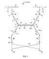
- Fig. 1 is a schematic representation of a dual-element end-fire array antenna with Q equalization in accordance with the invention.
- the linear array of radiating elements includes a rear element, shown as top- loaded monopole 10, and a forward element, shown as a similar monopole 12.
- Rear coupling means shown as comprising quarter wavelength transmission line section 14 having a first impedance Z a , is arranged for coupling signals to the rear element 10 from a rear junction point 18.
- forward coupling means shown as comprising quarter wavelength transmission line section 16 having a second impedance Z b , is arranged for coupling signals to the forward element 12 from a forward junction point 20.
- Input means shown as terminal 22, is provided for coupling input signals to the antenna for transmission and, reciprocally, for coupling received signals from the antenna to signal utilization circuits.
- Feed means for coupling a first signal portion of a reference phase from terminal 22 to rear junction point 18 and a second signal portion of lagging quadrature phase from terminal 22 to forward junction point 20, are shown as including a 3dB type directional coupler 24, a series resonant double-tuning circuit 26 (including inductance 28 and capacitance 30, in series) connecting to rear junction point 18, and a similar double-tuning circuit 32 connecting to forward junction point 20. While tuning circuits 26 and 32 are shown separated from junction points 18 and 20, respectively, to facilitate discussion of circuit design, in practice it will normally be desirable, when such tuning circuits are included, to connect them directly to the respective junction points.
- the antenna of Fig. 1 also includes Q equalization means, shown as quarter wavelength transmission line section 34 having an admittance Y c .
- means 34 provides an inter-element coupling impedance effective, in conjunction with impedances Z a and Z b , to increase the conductance component of the admittance at the rear junction point 18. While dimensions in Fig. 1 may be distorted for purposes of illustration, it should be noted that monopoles 10 and 12 are typically spaced by one-quarter of the free space wavelength and that references to wavelength refer to a wavelength in a frequency band in which an antenna is intended to operate, which may or may not be the same wavelength in successive such references.
- references to "end-fire” operation will be understood to refer to operation of an antenna to provide an antenna radiation pattern for transmission or reception which is primarily directed as indicated by arrow 36 in the example of the Fig. 1 antenna.
- References to a "quarter-wave” or “quarter wavelength” transmission line section refer to a transmission line section having an effective electrical length such that it provides a ninety degree phase delay, in a signal traveling along the line, at an operating frequency. In practice, some adjustment or tolerance may necessarily be involved in the design and implementation of a practical antenna.
- a basic quarter wavelength value or a quadrature relationship may actually be within a range of values, typically within plus or minus twenty degrees of the basic value, but which in some cases may depart by thirty degrees.
- the use of "nominally” equal values denotes instances in which the value of one parameter may differ within a range of twenty percent, and in some cases possibly by thirty-three percent from the value of a compared parameter.
- FIG. 1 DESIGN AND OPERATION
- Fig. 1 Description of the design and operation of the Fig. 1 antenna will be developed by first considering a two-element antenna as would be shown in Fig. 1 after removal of transmission line sections 14, 16 and 34. Line sections 14 and 16 are then replaced with simple conductors, while no connection is provided between junction points 18 and 20. Thus, the antenna configuration to first be considered includes two monopoles which are fed quadrature signals by action of the directional coupler 24. The presence or absence of tuning circuits 26 and 32 will not be important for purposes of the present discussion.
- Each monopole includes a 0.01 inch diameter vertical member supporting a horizontal 0.04 inch diameter, 1.96 inch long, top loading element with a center line spacing of 1.2 inches from the ground plane for use at a midband operating frequency of 1060 MHz.
- these elements have a self impedance (with reactance tuned out at mid band) Z s of 15.8 ⁇ and a mutual impedance Z m of 8.4 - j10.7 ⁇ .
- the self impedance of 15.8 ⁇ is essentially the radiation resistance of this electrically-short monopole.
- Fig. 1 antenna with the line sections 14, 16 and 34 in place, as shown. Assume first that the midband reactance of the elements is tuned out without changing the element resistance. Then add a nominal reactance Ax for the reactive effect for frequencies off midband and assume Ax is the same for both elements, which is a reasonable approximation for high-Q elements. Analysis of the Fig.
- the Q at each junction point is proportional to net B in /net G in . If the transmission line 34 was not present, Y c would be zero and the Q at junction point 18 would be greater than the Q at junction point 20 because R 1 is less than R 2 .
- the inter-element coupling impedance of the Q equalization line 34 is effective to cancel the effect of the element mutual reactance X m , thereby leaving both input resistances equal to the element self resistance R s transformed through the quarter wave lines 14 and 16, respectively.
- Z c will be positive when X m is negative (as in the present example). If X m were positive, then the inter-element coupling impedance would be provided by a transmission line section three-quarters wavelength long, in place of the one-quarter wavelength line 34, and the sign of equation (20) should be reversed.
- the desired R 1in and R 2in input values of 50 ⁇ are provided, in this example using the particular top-loaded monopoles as described above, by providing:
- a series tuning reactance for adjusting the impedance presented by each of elements 10 and 12 can be inserted at the respective element input/output ports 38 and 40.
- a shunt device should not be connected at these ports because that would change the current at that point.
- a conventional shunt double-tuning circuit should not be used at the element port.
- An appropriate double tuning circuit can be located at or below the respective rear and forward junction points 18 and 20.
- series resonant circuits 26 and 32 are coupled to these junction points.
- the circuits 26 and 32 may connect directly to the junction points 18 and 20.
- Alternative forms of double tuning circuits in antennas using the invention may include various combinations of line lengths, stubs, etc., as available in the prior art.
- the power of the first and second signal portions delivered to junction points 18 and 20 should be essentially equal.
- the desired signals can be provided by use of a 3dB type directional coupler 24, which is a known type of device including a resistive termination 42.
- tolerances on the measurement and specification of impedances, and other effects may require an adjustment of the directional coupler design to provide a coupling value somewhat different from 3dB in order to obtain optimum end-fire radiation performance.
- the term "3dB type" is used to indicate that adjustment may result in a coupler having coupling values differing somewhat from 3dB.
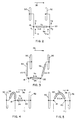
- Fig. 2 there is shown a conceptual form of dual slot antenna in accordance with the invention.
- the slots which may be elongated openings in the metal surface of an aircraft and may be backed-up by suitable cavity arrangements, may typically be one-half wavelength in length and spaced by one-quarter wavelength from each other.
- an end-fire radiation pattern directed to the right in Fig. 2 can be provided.
- the Fig. 2 slot configuration is simpler in not including the quarter wave lines 14 and 16 of Fig. 1, it is somewhat more complex in the implementation of connecting means capable of providing necessary electrical lengths or phase relationships for coupled signals.
- Fig. 3 shows the use of rear and forward transmission line sections 54 and 56, whose length is a multiple of one-half wavelength, to provide greater flexibility in positioning and intercoupling of the antenna components.
- the slots are similarly excited, i.e., both excitation leads connect to the same side of the slots (either the right side or the left side).
- Figs. 4 and 5 show arrangements wherein the slot excitation lines connect to opposite sides of the respective slots to provide a phase reversal relationship.
- a single half-wavelength line 58 is used to connect rear junction point 18 to rear slot 50, while forward slot 52 is directly connected to forward junction point 20.
- Fig. 4 shows the use of rear and forward transmission line sections 54 and 56, whose length is a multiple of one-half wavelength, to provide greater flexibility in positioning and intercoupling of the antenna components.
- the slots are similarly excited, i.e., both excitation leads connect to the same side of the slots (either the right side or the left side).
- Figs. 4 and 5 show arrangements
- a three-quarter wavelength transmission line 60 is connected between the junction points 18 and 20, and the forward junction point 20 is excited with a signal having leading quadrature phase.
- the arrangement is effective to provide a quadrature phase relationship between signal portions supplied to the two slot elements to provide an end-fire radiation pattern directed to the right in each drawing, provided the line length represented by the slot exciters is minimized, or taken into account, or both.
- Fig. 6 illustrates a Fig. 3 type dual slot antenna to which a feed arrangement similar to the Fig. 1 feed means has been added.
- the series resonant double tuning circuits 26a and 32a can appropriately be located in the respective feed paths just below the rear and forward junction points 18 and 20. If the transmission line sections 54, 56 and 34 are designed as described, the power of the rear and forward input signal portions delivered from the two outputs of the directional coupler 24, to junction points 18 and 20, should be essentially equal, as would be provided by a 3dB type coupler.
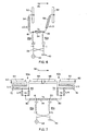
- a dual-element end-fire array implemented in the form of rear and forward slots 50a and 52a (shown in an end-view cross section) backed up by cavities 60 and 62.
- excitation of slot 50a is provided via a balanced exciter arrangement including dual conductors 64 connected at one end to the cavity wall and at the other end to a signal coupling means in the form of a balun 68 consisting of a Wilkinson type parallel line signal divider 70 and a half wavelength transmission line section 72.
- Forward slot 52a has a similar combination of exciter 66 coupled to signal coupling means in the form of balun 74, including half-wave line 76 and Wilkinson type divider 78.
- dividers 70 and 78 each include two parallel quarter wavelength sections coupled at one end by a resistor and interconnected at their other ends.
- the half-wave (or multiple thereof) lines 54 and 56 are replaced by transmission line segments 80 and 82.
- the electrical lengths of each of lines 80 and 82 is selected so that its length, in combination with the effective lengths of the respective exciter 64 or 66 and divider 70 or 78, equals a multiple of one-half wavelength.
- the line sections 72 and 76 merely add additional half-wavelength segments.
- any impedance transformation caused by the length of the exciters 64 and 66 and the quarter wavelength lines of dividers 70 and 78 and line segments 80 and 82 must be taken into account in determination of the value of Y c of inter-element coupling line 34.
- the monopoles are first set up above a large metal groundplane with the desired quarter wavelength spacing and with any intended radome in place over the radiators. Adjustments are then made as follows.
- A Adjust the relative phase and amplitude of quadrature phase signals supplied to the two elements to achieve a high front-to-back ratio of end-fire array radiation at mid-band.
- B Tune both monopoles (independently) for zero reactance at the monopole terminals at midband.
- C Repeat steps (A) and (B) until both a high front-to-back ratio and zero midband reactance for both monopoles are achieved simultaneously.
- the desired inter-element coupling impedance is more easily determined for a slot antenna embodiment.
- the slot elements are tuned, while excited with quadrature phase signals of adjustable relative amplitudes, as described at (A) and (B) above to achieve low element susceptance and a high front-to-back radiation level ratio.
- the inter-element coupling impedance corresponds inversely to one-half of the difference between the conductances of the two slot elements.
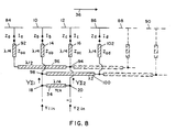
- FIG. 8 shows a linear array of four top-loaded monopoles, including monopoles 10 and 12 preceded by monopole 84 and followed by monopole 86, plus two additional similar monopoles 88 and 90, shown dotted as optional additions.
- the forced-feed configuration can be extended to element 86 which, as shown, is coupled to element 10 via point 98, half-wave line 100 and quarter-wave transformer 102. Additional elements, such as 88 and 90, may be added as desired by provision of half-wave lines which respectively couple the feeds to alternate monopole elements at points immediately below the quarter-wave sections, such as 16 and 102.
- the Fig. 8 type antenna can be viewed as establishing the basic feed relationship between two adjacent elements (i.e., 10 and 12) by use of the Q equalization inter-element coupling impedance of line 34, and then extending the signal feed arrangement to additional elements by forced feeding.
- Tuning circuits corresponding to 26 and 32 in Fig. 1, and a directional coupler, corresponding to 24 in Fig. 1, can be added to the Fig. 8 antenna as one appropriate way in which to provide the desired quadrature phase signals for end-fire operation.
Description
- The invention relates to multiple-element end-fire array antennas according the preamble of claim 1, and to a method for improving Q equalization of such antennas.
- The problem of providing antennas usable on the nose of high-speed fighter aircraft requires meeting antenna performance criteria, while also meeting constraints limiting size, height, pilot view obstruction, air resistance, available mounting space, overall complexity, etc. While in many cases prior art antenna designs are available to meet desired antenna performance criteria, typically such prior designs cannot meet the very real physical constraints imposed for applications on fighter aircraft.
- EP 0 435 562 A2 and EP 0 459 616 A2, respectively, relate to linear array antennas in which efficient broadband operation is achieved through forced excitation of three or more small radiating elements, and to antennas using a parallel array of such forced-fed antenna or other antennas.
- In attempting to design two-element end-fire arrays for applications subject to such constraints, it was found that antennas using relatively large radiating elements could be provided. However, no solution permitting use of small elements while maintaining desired antenna performance over a significant operating band of frequencies was available. With small elements used in an end-fire array of monopoles, for example, the rear element has unusually low radiation resistance because of effects of mutual coupling which are severe with the small elements. This low radiation resistance increases the Q of the rear monopole, resulting in a poor impedance match over an operating frequency band.
- In order to lower the Q of the rear element in such a two-element end-fire array, the height of the monopole could be increased or loss, i.e., series resistance could be inserted. Both of these approaches are undesirable, particularly in the applications in point. For a three-element end-fire array, a solution was provided in the referenced prior applications by effectively offsetting the low radiation resistance of the rear element with the high radiation resistance of the forward element by use of a forced excitation system. That solution was effective in the three element array because the rear and forward elements are excited with signals of opposite phase. However, in a two-element end-fire array the elements are excited in quadrature phase, which precludes use of the forced excitation system.
- It is therefore an object of this invention to provide improved dual-element end-fire array antennas suitable for aircraft applications, particularly those subject to size, height and other constraints, such that small radiating elements can be utilized.
- This object is being solved by the invention as defined in claims 1 and 14, respectively, with particular embodiments being described in the subclaims.
- The above-mentioned problem is solved by the multiple element end-fire array of Claim 1 and by the corresponding method according to Claim 14.
- In accordance with the invention, a dual-element end-fire array antenna with improved Q equalization includes a linear array of radiating elements including a rear element and forward element spaced by one-quarter wavelength at a frequency in an operating frequency band, rear coupling means, having a first impedance, for coupling signals to the rear element from a rear junction point, and forward coupling means, having a second impedance, for coupling signals to the forward element from a forward junction point. Also included are input means for coupling an input signal, feed means for coupling a first signal portion, having a reference phase, from the input means to the rear junction point and for coupling a second signal portion, having a nominally quadrature phase relation to the reference phase, from the input means to the forward junction point. The antenna further includes Q equalization means, coupled between the rear and forward junction points and having an effective length nominally equal to an odd multiple of one-quarter wavelength at a frequency in the operating frequency band, for providing an inter-element coupling impedance effective, in conjunction with the first and second impedances, to increase the conductance component of the admittance at the rear junction point.
- Also in accordance with the invention, a method for improving Q equalization in a dual-element monopole or dipole end-fire array antenna, comprises the steps of:
- (a) providing a pair of monopole or dipole radiating elements, including a rear element and a forward element;
- (b) tuning such elements, while exciting the elements with quadrature phase signals of adjustable relative amplitudes at a selected frequency, to achieve low element reactance and a high front-to-back radiation level ratio;
- (c) determining the active resistance of each of the rear and forward elements when tuned and excited as in step (b);
- (d) determining the average value of the active resistances as determined in step (c);
- (e) specifying the desired rear element input resistance and forward element input resistance;
- (f) inserting in series with the rear element a coupling device (such as a quarter-wave transmission line section) having an impedance corresponding to the square root of the product of the average value from step (d) times the rear element input resistance from step (e);
- (g) inserting in series with the forward element a coupling device (such as a quarter-wave transmission line section) having an impedance corresponding to the square root of the product of the average value from step (d) times the forward element input resistance from step (e);
- (h) inserting between the coupling devices, at junction points away from the radiating elements, a transmission line section of length equivalent to an odd multiple of a quarter wavelength at a desired frequency and having an impedance corresponding to twice the product of the impedances described in steps (f) and (g), divided by the difference between the respective active resistances of the radiating elements as determined in step (c).
-
- For a better understanding of the invention, together with other and further objects, reference is made to the following description taken in connection with the accompanying drawings and the scope will be pointed out in the appended claims.
- Fig. 1 shows schematically a dual-element end-fire array antenna utilizing monopoles, with an inter-element coupling impedance for Q equalization in accordance with the invention.
- Figs. 2, 3, 4, 5 and 6 show embodiments of dual-slot end-fire array antennas using the invention.
- Fig. 7 shows an arrangement including cavity-backed slots with balanced exciters and Q equalization.
- Fig. 8 shows a multi-element array using the Fig. 1 type element pair supplemented by additional forced-fed elements.
- Fig. 1 is a schematic representation of a dual-element end-fire array antenna with Q equalization in accordance with the invention. As illustrated, the linear array of radiating elements includes a rear element, shown as top- loaded monopole 10, and a forward element, shown as a similar monopole 12. Rear coupling means, shown as comprising quarter wavelength transmission line section 14 having a first impedance Za, is arranged for coupling signals to the rear element 10 from a rear junction point 18. Similarly, forward coupling means, shown as comprising quarter wavelength transmission line section 16 having a second impedance Zb, is arranged for coupling signals to the forward element 12 from a forward junction point 20. Input means, shown as terminal 22, is provided for coupling input signals to the antenna for transmission and, reciprocally, for coupling received signals from the antenna to signal utilization circuits. Feed means, for coupling a first signal portion of a reference phase from terminal 22 to rear junction point 18 and a second signal portion of lagging quadrature phase from terminal 22 to forward junction point 20, are shown as including a 3dB type directional coupler 24, a series resonant double-tuning circuit 26 (including inductance 28 and capacitance 30, in series) connecting to rear junction point 18, and a similar double-tuning circuit 32 connecting to forward junction point 20. While tuning circuits 26 and 32 are shown separated from junction points 18 and 20, respectively, to facilitate discussion of circuit design, in practice it will normally be desirable, when such tuning circuits are included, to connect them directly to the respective junction points.
- The antenna of Fig. 1 also includes Q equalization means, shown as quarter wavelength transmission line section 34 having an admittance Yc. As will be described in greater detail, means 34 provides an inter-element coupling impedance effective, in conjunction with impedances Za and Zb, to increase the conductance component of the admittance at the rear junction point 18. While dimensions in Fig. 1 may be distorted for purposes of illustration, it should be noted that monopoles 10 and 12 are typically spaced by one-quarter of the free space wavelength and that references to wavelength refer to a wavelength in a frequency band in which an antenna is intended to operate, which may or may not be the same wavelength in successive such references. Also, references to "end-fire" operation will be understood to refer to operation of an antenna to provide an antenna radiation pattern for transmission or reception which is primarily directed as indicated by arrow 36 in the example of the Fig. 1 antenna. References to a "quarter-wave" or "quarter wavelength" transmission line section refer to a transmission line section having an effective electrical length such that it provides a ninety degree phase delay, in a signal traveling along the line, at an operating frequency. In practice, some adjustment or tolerance may necessarily be involved in the design and implementation of a practical antenna. In view of this, "nominally" is used to indicate that a basic quarter wavelength value or a quadrature relationship may actually be within a range of values, typically within plus or minus twenty degrees of the basic value, but which in some cases may depart by thirty degrees. Similarly, the use of "nominally" equal values denotes instances in which the value of one parameter may differ within a range of twenty percent, and in some cases possibly by thirty-three percent from the value of a compared parameter.
- Description of the design and operation of the Fig. 1 antenna will be developed by first considering a two-element antenna as would be shown in Fig. 1 after removal of transmission line sections 14, 16 and 34. Line sections 14 and 16 are then replaced with simple conductors, while no connection is provided between junction points 18 and 20. Thus, the antenna configuration to first be considered includes two monopoles which are fed quadrature signals by action of the directional coupler 24. The presence or absence of tuning circuits 26 and 32 will not be important for purposes of the present discussion.
- For purposes of analysis, consider an example based upon use of two previously-developed top-loaded monopoles with quarter wave separation and having the following dimensions and relevant characteristics. Each monopole includes a 0.01 inch diameter vertical member supporting a horizontal 0.04 inch diameter, 1.96 inch long, top loading element with a center line spacing of 1.2 inches from the ground plane for use at a midband operating frequency of 1060 MHz. By computer computation, these elements have a self impedance (with reactance tuned out at mid band) Zs of 15.8 Ω and a mutual impedance Zm of 8.4 - j10.7 Ω. The self impedance of 15.8 Ω is essentially the radiation resistance of this electrically-short monopole.
- For an active end-fire array:
- Reference is now made to the Fig. 1 antenna with the line sections 14, 16 and 34 in place, as shown. Assume first that the midband reactance of the elements is tuned out without changing the element resistance. Then add a nominal reactance Ax for the reactive effect for frequencies off midband and assume Ax is the same for both elements, which is a reasonable approximation for high-Q elements. Analysis of the Fig. 1 antenna system yields:
- With reference to equations (2) and (4) it will be seen that the resistive components of the active impedances of the elements have the form:
- Attention will now be directed to the proportioning of line impedances in application of the invention to practical antennas. Assume now that it is desired, in a particular antenna, to provide that both R1in and R2in have values of 50 Ω.
- In this case:
- Thus, the desired R1in and R2in input values of 50 Ω are provided, in this example using the particular top-loaded monopoles as described above, by providing:
- line section 34 as a quarter wave line having an impedance of 73.8 Ω, and
- line sections 14 and 16 as quarter wave lines each having an impedance of 28.1 Ω.
- Referring now to the complete antenna as represented in Fig. 1, the following should be observed. A series tuning reactance for adjusting the impedance presented by each of elements 10 and 12 can be inserted at the respective element input/output ports 38 and 40. However, a shunt device should not be connected at these ports because that would change the current at that point. Thus, a conventional shunt double-tuning circuit should not be used at the element port. An appropriate double tuning circuit can be located at or below the respective rear and forward junction points 18 and 20. In the illustrated example, series resonant circuits 26 and 32 are coupled to these junction points. As noted above, while certain dimensions in Fig. 1 have been distorted to aid in descriptive circuit analysis, in practice the circuits 26 and 32 may connect directly to the junction points 18 and 20. Alternative forms of double tuning circuits in antennas using the invention may include various combinations of line lengths, stubs, etc., as available in the prior art.
- If the transmission line sections 14, 16 and 34 are designed as described, the power of the first and second signal portions delivered to junction points 18 and 20 (as provided by the two outputs of directional coupler 24) should be essentially equal. Thus, the desired signals can be provided by use of a 3dB type directional coupler 24, which is a known type of device including a resistive termination 42. In practice, tolerances on the measurement and specification of impedances, and other effects, may require an adjustment of the directional coupler design to provide a coupling value somewhat different from 3dB in order to obtain optimum end-fire radiation performance. The term "3dB type" is used to indicate that adjustment may result in a coupler having coupling values differing somewhat from 3dB. Also, if the reactive portions of the active element impedances Z1 and Z2 are tuned out (i.e., X1 = X2 = 0) at mid-band, then the desired quadrature phase relationship of currents in the elements 10 and 12 can be provided by coupler 24. In practice, some adjustment of phase may be necessary during design to yield best results.
- Referring now to Fig. 2, there is shown a conceptual form of dual slot antenna in accordance with the invention. The slots, which may be elongated openings in the metal surface of an aircraft and may be backed-up by suitable cavity arrangements, may typically be one-half wavelength in length and spaced by one-quarter wavelength from each other. As with the Fig. 1 antenna, by appropriately providing quadrature relationship signals to rear slot element 50 and forward slot element 52 of Fig. 2, an end-fire radiation pattern directed to the right in Fig. 2 can be provided. As will be further described, although the Fig. 2 slot configuration is simpler in not including the quarter wave lines 14 and 16 of Fig. 1, it is somewhat more complex in the implementation of connecting means capable of providing necessary electrical lengths or phase relationships for coupled signals.
- With reference to Fig. 2 and consistent with the preceding discussion, for the dual slot configuration:
- Fig. 3 shows the use of rear and forward transmission line sections 54 and 56, whose length is a multiple of one-half wavelength, to provide greater flexibility in positioning and intercoupling of the antenna components. In both Fig. 2 and Fig. 3 the slots are similarly excited, i.e., both excitation leads connect to the same side of the slots (either the right side or the left side). Figs. 4 and 5 show arrangements wherein the slot excitation lines connect to opposite sides of the respective slots to provide a phase reversal relationship. In Fig. 4, a single half-wavelength line 58 is used to connect rear junction point 18 to rear slot 50, while forward slot 52 is directly connected to forward junction point 20. In Fig. 5 a three-quarter wavelength transmission line 60 is connected between the junction points 18 and 20, and the forward junction point 20 is excited with a signal having leading quadrature phase. In each of these embodiments the arrangement is effective to provide a quadrature phase relationship between signal portions supplied to the two slot elements to provide an end-fire radiation pattern directed to the right in each drawing, provided the line length represented by the slot exciters is minimized, or taken into account, or both.
- Fig. 6 illustrates a Fig. 3 type dual slot antenna to which a feed arrangement similar to the Fig. 1 feed means has been added. As shown in Fig. 6, the series resonant double tuning circuits 26a and 32a can appropriately be located in the respective feed paths just below the rear and forward junction points 18 and 20. If the transmission line sections 54, 56 and 34 are designed as described, the power of the rear and forward input signal portions delivered from the two outputs of the directional coupler 24, to junction points 18 and 20, should be essentially equal, as would be provided by a 3dB type coupler. If the active element susceptances are tuned out (B1 = B2 = 0) at midband, then the quadrature phase signal relationship provided by directional coupler 24 should quite accurately yield the desired quadrature voltages at the slots 50 and 52. It will be understood, that in accordance with established antenna design practices, coupling and phase values may require some adjustment during design in order to provide optimum end-fire radiation performance.
- With reference now to Fig. 7, there is illustrated a specific embodiment of a dual-element end-fire array implemented in the form of rear and forward slots 50a and 52a (shown in an end-view cross section) backed up by cavities 60 and 62. In this embodiment, excitation of slot 50a is provided via a balanced exciter arrangement including dual conductors 64 connected at one end to the cavity wall and at the other end to a signal coupling means in the form of a balun 68 consisting of a Wilkinson type parallel line signal divider 70 and a half wavelength transmission line section 72. Forward slot 52a has a similar combination of exciter 66 coupled to signal coupling means in the form of balun 74, including half-wave line 76 and Wilkinson type divider 78. As shown, dividers 70 and 78 each include two parallel quarter wavelength sections coupled at one end by a resistor and interconnected at their other ends. In the Fig. 7 circuit the half-wave (or multiple thereof) lines 54 and 56 are replaced by transmission line segments 80 and 82. The electrical lengths of each of lines 80 and 82 is selected so that its length, in combination with the effective lengths of the respective exciter 64 or 66 and divider 70 or 78, equals a multiple of one-half wavelength. The line sections 72 and 76 merely add additional half-wavelength segments. However, any impedance transformation caused by the length of the exciters 64 and 66 and the quarter wavelength lines of dividers 70 and 78 and line segments 80 and 82 must be taken into account in determination of the value of Yc of inter-element coupling line 34.
- Following is one approach to the basic design and adjustment of a Fig. 1 type of antenna for use of the invention.
- The monopoles are first set up above a large metal groundplane with the desired quarter wavelength spacing and with any intended radome in place over the radiators. Adjustments are then made as follows. (A) Adjust the relative phase and amplitude of quadrature phase signals supplied to the two elements to achieve a high front-to-back ratio of end-fire array radiation at mid-band. (B) Tune both monopoles (independently) for zero reactance at the monopole terminals at midband. (C) Repeat steps (A) and (B) until both a high front-to-back ratio and zero midband reactance for both monopoles are achieved simultaneously. Then, measure the active resistance components (R1 and R2) at the monopole terminals and compute the value of Rs = (R2 + R1)/2. Specify the desired values of R1in and R2in, which are typically 50 n. Compute the values of:
- This basic design approach may be applied for monopole, dipole or slot antennas by persons skilled in antenna system design, with variations and augmentation as may be appropriate in different applications and varied forms of antennas using the invention. More particularly, the desired inter-element coupling impedance is more easily determined for a slot antenna embodiment. First the slot elements are tuned, while excited with quadrature phase signals of adjustable relative amplitudes, as described at (A) and (B) above to achieve low element susceptance and a high front-to-back radiation level ratio. Then after determining the active conductance of each slot element as tuned, the inter-element coupling impedance corresponds inversely to one-half of the difference between the conductances of the two slot elements.
- As discussed above, the inventor's prior application serial 07/458,220 describes linear array antennas having three or more small radiating elements and in which forced excitation is employed to achieve efficient end-fire operation. The disclosure of such application is hereby incorporated by reference into the present description.
- With reference now to Fig. 8, there is illustrated an embodiment of the present invention which additionally incorporates forced feeding in a multiple element linear array utilizing the present invention. Fig. 8 shows a linear array of four top-loaded monopoles, including monopoles 10 and 12 preceded by monopole 84 and followed by monopole 86, plus two additional similar monopoles 88 and 90, shown dotted as optional additions.
- Initially considering only monopole elements 10 and 12 in Fig. 8, it will be seen that the combination of elements 10 and 12, quarter wave sections 14 and 16, rear and forward junction points 18 and 20, and inter-element coupling line 34 are arranged as in Fig. 1. The elements 10 and 12, when appropriately excited in quadrature, thus provide a dual-element end-fire array as previously described. Considering now only the monopole elements 12 and 84, it will be seen that (with quarter wave spacing of elements 10 and 12 and the same spacing of remaining elements) the elements 12 and 84 are spaced by one-half wavelength and, for end-fire operation, are appropriately excited with signals of opposite phase. As fully explained in said application 07/458,220, the provision of line sections 16 and 92 (which provide the function of quarter wave transformers) and half-wave line section 96 enable elements 12 and 84 to be force fed, via point 94 (which acts as a point of common voltage). A result of such forced feeding is that mutual coupling between elements, which would otherwise severely distort the desired relationship between currents in elements 12 and 84, does not distort that relationship. The forced-feed configuration, in accordance with the inventor's prior invention and including element 10 between the two forced fed elements in accordance with the present invention, thus permits provision of an end-fire radiation pattern with small closely spaced elements.
- With this brief overview, as augmented by the prior specification, the forced-feed configuration can be extended to element 86 which, as shown, is coupled to element 10 via point 98, half-wave line 100 and quarter-wave transformer 102. Additional elements, such as 88 and 90, may be added as desired by provision of half-wave lines which respectively couple the feeds to alternate monopole elements at points immediately below the quarter-wave sections, such as 16 and 102. Thus, it will be seen that the Fig. 8 type antenna can be viewed as establishing the basic feed relationship between two adjacent elements (i.e., 10 and 12) by use of the Q equalization inter-element coupling impedance of line 34, and then extending the signal feed arrangement to additional elements by forced feeding. Tuning circuits, corresponding to 26 and 32 in Fig. 1, and a directional coupler, corresponding to 24 in Fig. 1, can be added to the Fig. 8 antenna as one appropriate way in which to provide the desired quadrature phase signals for end-fire operation.
- In the design of a Fig. 8 type antenna effective end-fire performance can be achieved on the basis of equalizing the Qs at the two input ports. Consistent with design analysis relating to the Fig. 1 antenna, if Q1 is to equal Q2, necessary relationships are as follows, assuming
Zob/Zod ≡ Zoc/Zoa ≡ k, then:
Claims (18)
- A multiple element end-fire array antenna of a type including a linear array of radiating elements having a rear element (10) and a forward element (12), rear coupling means (14) having a first impedance, for coupling signals to said rear element (10) from a junction point (18), forward coupling means (16) having a second impedance, for coupling signals to said forward element (12) from a junction point (20), and feed means (24) for coupling signals from input means (22) to the junction points (18,20), characterized in that in a dual-element end-fire array antenna improved Q equalization is provided by:said feed means (24) coupling a first signal portion, having a reference phase, from said input means (22) to a rear junction point (18) and coupling a second signal portion, having a nominally quadrature phase relation to said reference phase, from said input means (22) to a forward junction point (20); and in thatbetween said rear and forward junction points (18,20) Q equalization means (34) is coupled which has an effective length nominally equal to an odd multiple of one-quarter wavelength at a frequency in an operating frequency band, for providing an inter-element coupling impedance effective, in conjunction with said first and second impedances, to increase the conductance component of the admittance at said rear junction point (18).
- An array antenna as in claim 1, characterized in that said Q equalization means (34) comprises a quarter wavelenght transmission line section of impedance Zc approximately equal to Rs (the self resistance of each of said rear and forward elements) divided by Xm (the mutual reactance of said rear and forward elements, stated as a positive value) times the square root of R1in times R2in (the product of the input resistances at said rear and forward junction points).
- An array antenna as in claim 1 or 2, characterized in that feed means (24) comprises a 3 dB type directional coupler.
- An array antenna as in claim 1, 2 or 3, characterized in that said feed means additionally comprises two double-tuning circuits (26,32), one connected to each of said rear and forward junction points (18,20).
- An array antenna as in any preceding claim, characterized by additionally comprising:a back element (84), positioned to the rear of said rear element (10), and a front element (86), positioned forward of said forward element (12), said back, rear, forward and front elements being similar radiating elements arranged in a linear array with inter-element spacing of one-quarter wavelength at said frequency in said operating frequency band;back coupling means (92) for coupling signals to said back element (84);front coupling means (102) for coupling signals to said front element (86);a back feed line (96) for coupling signals from said forward junction point (94) to said back coupling means (92) to feed said back element (84); anda front feed line (100) for coupling signals from said rear junction point (98) to said front coupling means (102) to feed said front element (86) (Fig. 8).
- An array antenna as in any preceding claim, characterized in thatwith the input impedance to each of said rear and forward elements (10,12) being 50 ohms,said first and second impedances (of said rear and forward coupling means 14 and 16, resp.) each have a value nominally equal to the value of the square root of the product of the average of the mid-band active resistances of said rear and forward elements (10,12) times 50 ohms; andsaid inter-element coupling impedance (of equalization means 34) has a value nominally equal to twice the product of said first and second impedances, divided by the difference between said mid-band active resistances of said forward and rear elements (12 and 10 resp.).
- An array antenna as in any preceding claim, characterized in that said radiating elements are two monopoles (10,12) spaced by one-quarter wavelength at a frequency in an operating frequency band, said rear and forward coupling means (14 and 16, resp.) are quarter wavelength transmission line sections (14,16), and said equalization means (34) is a quarter wavelength transmission line section.
- An array antenna as in claim 1, 2, 3, 4, 5 or 6, characterized in that said radiating elements are two slot radiating elements (50,52) and said Q equalization means (34) is a transmission line section having an effective electrical length equal to an odd multiple of a quarter wavelength at a frequency in an operating frequency band.
- An array antenna as in claim 8, characterized in that each of said rear and forward coupling means is a transmission line section (54,56) which is a multiple of one-half wavelength long at a frequency in said operating frequency band.
- An array antenna as in claim 8, characterized in that said rear coupling means is a transmission line section (58) one-half wavelength long at a frequency in said operating frequency band.
- An array antenna as in claim 8, characterized in that said Q equalization means (34) is three-quarters of said wavelength long for providing said inter-element coupling impedance.
- An array antenna as in claim 8, 9, 10 or 11, characterized in that said slot elements are rear and forward cavity-backed slot radiating elements (50a,52a).
- An array antenna as in claim 12, characterized in that said rear and forward coupling means each comprises: a balanced exciter (64,66) connecting to walls of the cavity (60,62) backing the respective slot radiating element (50a, 52a), a balun (68,74) feeding said balanced exciter, and a transmission line section (72,76) having a length selected to cause the total effective series length of said balanced exciter, said balun and said transmission line section to be equal to one-half wavelength at a frequency in said operating frequency band.
- A method for improving Q equalization in a dual-element end-fire array antenna including rear and forward radiating elements (10,12), characterized by the steps of:a) tuning said elements (10,12), while exciting said elements with quadrature phase signals of adjustable relative amplitudes at a selected frequency, to achieve low element reactance and a high front-to-back radiation level ratio;b) determing the active resistance of each of said rear and forward elements (10,12) when tuned and excited as in step a);c) determining the average value of said active resistance as determined in step b);d) specifying the desired rear input port resistance and forward input port resistance;e) inserting in series with said rear element (10) a coupling device (14) having an impedance nominally equal to the square root of the product of said average value from step c) times said rear input port resistance from step d);f) inserting in series with said forward element (12) a coupling device (16) having an impedance nominally equal to the square root of the product of said average value from step c) times said forward input port resistance from step d) andg) inserting between said coupling devices, at junction points away from said radiating elements, a transmission line section (34) of length nominally equal to an odd multiple of a quarter wavelength at a desired frequency and having an impedance corresponding to twice the product of the impedances described in steps e) and f), divided by the difference between the respective active resistances of said radiating elements as determined in step b).
- A method as in claim 14, characterized in that said elements (10,12) are tuned and said relative amplitudes are adjusted in step a) to minimize element reactance and simultaneously maximize said front-to-back radiation level ratio.
- A method as in claim 14 or 15, characterized in that said rear and forward elements (10,12) are monopoles and said coupling devices (14,16) referred to in steps e) and f) are quarter wavelength transmission line sections having impedances as respectively determined in said steps e) and f).
- A method as in claim 14, characterized in that in step a) said rear and forward elements being comprised by slot elements (50,52) are tuned to achieve low element susceptance and a high front-to-back radiation level ratio, and in that in step b) active conductance of each slot element (50,52) is determined, and steps c) through f) are replaced by:c) inserting between said slot elements (50,52), a transmission line section (34) of length nominally equal to an odd multiple of a quarter wavelength at a desired frequency and having an impedance corresponding to the inverse of one-half of the difference between said conductances of said rear and forward slot elements as determined in step b).
- A method as in claim 17, characterized in that said slot elements (50,52) are tuned and said relativ amplitudes are adjusted in step a) to minimize element susceptance and simultaneously maximize said front-to-back radiation level ratio.
Applications Claiming Priority (3)
| Application Number | Priority Date | Filing Date | Title |
|---|---|---|---|
| US08/086,807 US5369413A (en) | 1993-07-02 | 1993-07-02 | Q equalization in dual-element end-fire array antennas |
| PCT/US1994/007463 WO1995001662A1 (en) | 1993-07-02 | 1994-07-01 | Q equalization in dual-element end-fire array antennas |
| US86807 | 2002-03-04 |
Publications (2)
| Publication Number | Publication Date |
|---|---|
| EP0658282A1 EP0658282A1 (en) | 1995-06-21 |
| EP0658282B1 true EP0658282B1 (en) | 1999-10-06 |
Family
ID=22201050
Family Applications (1)
| Application Number | Title | Priority Date | Filing Date |
|---|---|---|---|
| EP94921450A Expired - Lifetime EP0658282B1 (en) | 1993-07-02 | 1994-07-01 | Q equalization in dual-element end-fire array antennas |
Country Status (7)
| Country | Link |
|---|---|
| US (1) | US5369413A (en) |
| EP (1) | EP0658282B1 (en) |
| JP (1) | JP3359637B2 (en) |
| DE (1) | DE69421046T2 (en) |
| IL (1) | IL110184A (en) |
| TW (1) | TW255061B (en) |
| WO (1) | WO1995001662A1 (en) |
Families Citing this family (3)
| Publication number | Priority date | Publication date | Assignee | Title |
|---|---|---|---|---|
| US7532170B1 (en) * | 2001-01-25 | 2009-05-12 | Raytheon Company | Conformal end-fire arrays on high impedance ground plane |
| US7277403B2 (en) * | 2001-12-13 | 2007-10-02 | Avago Technologies Wireless Ip (Singapore) Pte Ltd | Duplexer with a differential receiver port implemented using acoustic resonator elements |
| US9543660B2 (en) | 2014-10-09 | 2017-01-10 | Apple Inc. | Electronic device cavity antennas with slots and monopoles |
Family Cites Families (7)
| Publication number | Priority date | Publication date | Assignee | Title |
|---|---|---|---|---|
| US3255450A (en) * | 1960-06-15 | 1966-06-07 | Sanders Associates Inc | Multiple beam antenna system employing multiple directional couplers in the leadin |
| GB1003317A (en) * | 1961-07-28 | 1965-09-02 | Standard Telephones Cables Ltd | Radio navigational system |
| DE8806101U1 (en) * | 1988-05-07 | 1989-09-07 | Hans Kloeber Kg, 5828 Ennepetal, De | |
| US4983988A (en) * | 1988-11-21 | 1991-01-08 | E-Systems, Inc. | Antenna with enhanced gain |
| US5206656A (en) * | 1989-12-28 | 1993-04-27 | Hannan Peter W | Array antenna with forced excitation |
| CA2030600C (en) * | 1990-05-29 | 2000-04-25 | Peter Hannan | Aircraft antenna with coning and banking correction |
| US5214436A (en) * | 1990-05-29 | 1993-05-25 | Hazeltine Corp. | Aircraft antenna with coning and banking correction |
-
1993
- 1993-07-02 US US08/086,807 patent/US5369413A/en not_active Expired - Lifetime
-
1994
- 1994-07-01 WO PCT/US1994/007463 patent/WO1995001662A1/en active IP Right Grant
- 1994-07-01 JP JP50366895A patent/JP3359637B2/en not_active Expired - Fee Related
- 1994-07-01 IL IL110184A patent/IL110184A/en not_active IP Right Cessation
- 1994-07-01 EP EP94921450A patent/EP0658282B1/en not_active Expired - Lifetime
- 1994-07-01 DE DE69421046T patent/DE69421046T2/en not_active Expired - Fee Related
- 1994-07-05 TW TW083106137A patent/TW255061B/zh active
Also Published As
| Publication number | Publication date |
|---|---|
| TW255061B (en) | 1995-08-21 |
| JP3359637B2 (en) | 2002-12-24 |
| JPH08505501A (en) | 1996-06-11 |
| WO1995001662A1 (en) | 1995-01-12 |
| IL110184A (en) | 1997-03-18 |
| EP0658282A1 (en) | 1995-06-21 |
| DE69421046T2 (en) | 2000-06-29 |
| US5369413A (en) | 1994-11-29 |
| DE69421046D1 (en) | 1999-11-11 |
Similar Documents
| Publication | Publication Date | Title |
|---|---|---|
| US6121937A (en) | Log-periodic staggered-folded-dipole antenna | |
| US6028562A (en) | Dual polarized slotted array antenna | |
| KR101146791B1 (en) | Method and apparatus for increasing performance in a waveguide-based spatial power combiner | |
| US3740754A (en) | Broadband cup-dipole and cup-turnstile antennas | |
| US6057804A (en) | Parallel fed collinear antenna array | |
| US7245268B2 (en) | Quadrifilar helical antenna | |
| US3971032A (en) | Dual frequency microstrip antenna structure | |
| US6064348A (en) | Method and apparatus for a dual frequency band antenna | |
| US4668956A (en) | Broadband cup antennas | |
| JPH11317614A (en) | Microstrip antenna and device provided with the antenna | |
| US4283729A (en) | Multiple beam antenna feed | |
| US4905011A (en) | Concentric ring antenna | |
| US5969687A (en) | Double-delta turnstile antenna | |
| WO2014190062A1 (en) | Negative group delay circuit | |
| Filipovic et al. | Novel slot spiral antenna designs for dual-band/multiband operation | |
| US4584582A (en) | Multi-mode direction finding antenna | |
| US5790082A (en) | Double-delta log-periodic antenna | |
| EP0658282B1 (en) | Q equalization in dual-element end-fire array antennas | |
| KR100198687B1 (en) | Array antenna with forced excitation | |
| US5103238A (en) | Twisted Z omnidirectional antenna | |
| JPS61252701A (en) | Circularly polarized wave generating loop antenna | |
| CN109509964A (en) | A kind of broadband circle polarized array antenna | |
| US6411264B1 (en) | Two-element driven array with improved tuning and matching | |
| US3036302A (en) | Sheet type balanced doublet antenna structure | |
| US11367962B1 (en) | Indirectly fed dipole antenna |
Legal Events
| Date | Code | Title | Description |
|---|---|---|---|
| PUAI | Public reference made under article 153(3) epc to a published international application that has entered the european phase |
Free format text: ORIGINAL CODE: 0009012 |
|
| AK | Designated contracting states |
Kind code of ref document: A1 Designated state(s): DE FR IT |
|
| 17P | Request for examination filed |
Effective date: 19950619 |
|
| 17Q | First examination report despatched |
Effective date: 19971107 |
|
| GRAG | Despatch of communication of intention to grant |
Free format text: ORIGINAL CODE: EPIDOS AGRA |
|
| GRAG | Despatch of communication of intention to grant |
Free format text: ORIGINAL CODE: EPIDOS AGRA |
|
| GRAH | Despatch of communication of intention to grant a patent |
Free format text: ORIGINAL CODE: EPIDOS IGRA |
|
| GRAH | Despatch of communication of intention to grant a patent |
Free format text: ORIGINAL CODE: EPIDOS IGRA |
|
| GRAA | (expected) grant |
Free format text: ORIGINAL CODE: 0009210 |
|
| AK | Designated contracting states |
Kind code of ref document: B1 Designated state(s): DE FR IT |
|
| REF | Corresponds to: |
Ref document number: 69421046 Country of ref document: DE Date of ref document: 19991111 |
|
| ITF | It: translation for a ep patent filed |
Owner name: BARZANO' E ZANARDO ROMA S.P.A. |
|
| RAP2 | Party data changed (patent owner data changed or rights of a patent transferred) |
Owner name: MARCONI AEROSPACE SYSTEMS INC. |
|
| ET | Fr: translation filed | ||
| PLBE | No opposition filed within time limit |
Free format text: ORIGINAL CODE: 0009261 |
|
| STAA | Information on the status of an ep patent application or granted ep patent |
Free format text: STATUS: NO OPPOSITION FILED WITHIN TIME LIMIT |
|
| 26N | No opposition filed | ||
| PGFP | Annual fee paid to national office [announced via postgrant information from national office to epo] |
Ref country code: IT Payment date: 20060731 Year of fee payment: 13 |
|
| PG25 | Lapsed in a contracting state [announced via postgrant information from national office to epo] |
Ref country code: IT Free format text: LAPSE BECAUSE OF NON-PAYMENT OF DUE FEES Effective date: 20070701 |
|
| PGFP | Annual fee paid to national office [announced via postgrant information from national office to epo] |
Ref country code: FR Payment date: 20090717 Year of fee payment: 16 |
|
| PGFP | Annual fee paid to national office [announced via postgrant information from national office to epo] |
Ref country code: DE Payment date: 20090729 Year of fee payment: 16 |
|
| REG | Reference to a national code |
Ref country code: FR Ref legal event code: ST Effective date: 20110331 |
|
| PG25 | Lapsed in a contracting state [announced via postgrant information from national office to epo] |
Ref country code: DE Free format text: LAPSE BECAUSE OF NON-PAYMENT OF DUE FEES Effective date: 20110201 |
|
| REG | Reference to a national code |
Ref country code: DE Ref legal event code: R119 Ref document number: 69421046 Country of ref document: DE Effective date: 20110201 |
|
| PG25 | Lapsed in a contracting state [announced via postgrant information from national office to epo] |
Ref country code: FR Free format text: LAPSE BECAUSE OF NON-PAYMENT OF DUE FEES Effective date: 20100802 |