EP0657968B1 - Lock detection connector - Google Patents
Lock detection connector Download PDFInfo
- Publication number
- EP0657968B1 EP0657968B1 EP94116642A EP94116642A EP0657968B1 EP 0657968 B1 EP0657968 B1 EP 0657968B1 EP 94116642 A EP94116642 A EP 94116642A EP 94116642 A EP94116642 A EP 94116642A EP 0657968 B1 EP0657968 B1 EP 0657968B1
- Authority
- EP
- European Patent Office
- Prior art keywords
- connector
- short circuit
- lock detecting
- circuit terminal
- cover
- Prior art date
- Legal status (The legal status is an assumption and is not a legal conclusion. Google has not performed a legal analysis and makes no representation as to the accuracy of the status listed.)
- Expired - Lifetime
Links
Images


Classifications
-
- H—ELECTRICITY
- H01—ELECTRIC ELEMENTS
- H01R—ELECTRICALLY-CONDUCTIVE CONNECTIONS; STRUCTURAL ASSOCIATIONS OF A PLURALITY OF MUTUALLY-INSULATED ELECTRICAL CONNECTING ELEMENTS; COUPLING DEVICES; CURRENT COLLECTORS
- H01R13/00—Details of coupling devices of the kinds covered by groups H01R12/70 or H01R24/00 - H01R33/00
- H01R13/66—Structural association with built-in electrical component
- H01R13/70—Structural association with built-in electrical component with built-in switch
- H01R13/703—Structural association with built-in electrical component with built-in switch operated by engagement or disengagement of coupling parts, e.g. dual-continuity coupling part
- H01R13/7031—Shorting, shunting or bussing of different terminals interrupted or effected on engagement of coupling part, e.g. for ESD protection, line continuity
- H01R13/7032—Shorting, shunting or bussing of different terminals interrupted or effected on engagement of coupling part, e.g. for ESD protection, line continuity making use of a separate bridging element directly cooperating with the terminals
-
- H—ELECTRICITY
- H01—ELECTRIC ELEMENTS
- H01R—ELECTRICALLY-CONDUCTIVE CONNECTIONS; STRUCTURAL ASSOCIATIONS OF A PLURALITY OF MUTUALLY-INSULATED ELECTRICAL CONNECTING ELEMENTS; COUPLING DEVICES; CURRENT COLLECTORS
- H01R13/00—Details of coupling devices of the kinds covered by groups H01R12/70 or H01R24/00 - H01R33/00
- H01R13/64—Means for preventing incorrect coupling
- H01R13/641—Means for preventing incorrect coupling by indicating incorrect coupling; by indicating correct or full engagement
-
- H—ELECTRICITY
- H01—ELECTRIC ELEMENTS
- H01R—ELECTRICALLY-CONDUCTIVE CONNECTIONS; STRUCTURAL ASSOCIATIONS OF A PLURALITY OF MUTUALLY-INSULATED ELECTRICAL CONNECTING ELEMENTS; COUPLING DEVICES; CURRENT COLLECTORS
- H01R13/00—Details of coupling devices of the kinds covered by groups H01R12/70 or H01R24/00 - H01R33/00
- H01R13/62—Means for facilitating engagement or disengagement of coupling parts or for holding them in engagement
- H01R13/627—Snap or like fastening
- H01R13/6271—Latching means integral with the housing
- H01R13/6272—Latching means integral with the housing comprising a single latching arm
Definitions
- the present invention relates to a lock detecting connector which can detect that a pair of connectors engageable with each other are in a completely locked state.
- Fig. 1 shows a conventionally known lock detecting structure of this type.
- a groove-like engagement portion la is formed on the upper surface of a connector 1 on the male side that is firmly fixed on a board 2.
- a flexible lock piece having a projection 7a is integrally formed on the upper surface of a connector 5 on the female side to be engaged with the connector 1 on the male side, the projection 7a being held by the engagement portion la when both connectors 1, 5 are connected.
- a pair of lock detecting electrodes 4a, 4b is disposed while positioned on both sides of an inverted T-shaped position determining piece 3 as shown in Fig. 2.
- a U-shaped short circuit electrode 6 is arranged so as to interpose the position determining piece 3 between the leg portions thereof as shown in Fig. 2.
- the short circuit electrode 6 is elastically deformed upward by a guide projection 3b formed on a partition wall 3a of the position determining piece 3 as shown in Fig. 3, so that the short circuit electrode 6 keeps distance from the detecting electrodes 4a, 4b at the initial stage of the insertion. Then, when the connector 5 on the female side has been inserted into a regular position of the connector 1 on the male side, the projection 7a of the flexible lock piece 7 is held by the engagement portion la to thereby unremovably lock both connectors 1, 5.
- the short circuit electrode 6 comes out of the projection 3b to come in contact with the lock detecting electrodes 4a, 4b as shown in Fig. 4.
- the lock detecting electrodes 4a, 4b are connected to a not shown detecting circuit, so that it is judged that both connectors 1, 5 have been connected in the locked state by way of short-circuiting the lock detecting electrodes 4a, 4b.
- the short circuit electrode 6 is disposed within the connector 5 on the female side.
- This structure is advantageous in preventing the detecting electrodes 4a, 4b from being shortcircuited while insulated by foreign matter such as dirt and dust upon contact between the detecting electrodes 4a, 4b and the short circuit electrode 6, since foreign matter is hard to deposit on the short circuit electrode 6.
- this structure does not allow the user to check the condition of the short circuit electrode 6 visibly; i.e., the short circuit electrode 6 is left concealed, and this is undesirable in terms of quality control.
- the short circuit electrode may be disposed on the outer surface of the connector, and a cover may be provided to cover the entire part of the connector having the short circuit electrode as long as the connector having the short circuit electrode is not connected to the mating connector.
- the cover may be removed to expose the short circuit electrode when the short circuit electrode must be inspected visibly or when the connector having the short circuit electrode is connected to the mating connector.
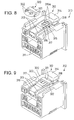
- FIG. 5 shows a connector housing 40 on the male side.
- a plurality of male terminals 41 is accommodated within the housing 40, and these terminals 41 project outward through the wall surface in the back of the housing 40.
- a rib 42 which extends in parallel with the terminals 41 within the housing 40.
- a partition wall 43 standing upright in the middle of the rib 42 divides the upper surface of the rib 42 into right and left parts.
- Lock detecting terminals 44 are disposed on such right and left parts of the rib 42. Both lock detecting terminals 44 project outward through the wall surface in the back of the housing 40 like other terminals.
- a connector housing 45 on the female side accommodates a not particularly shown short circuit terminal.
- the short circuit terminal has such a shape as to come in contact with the lock detecting terminals 44 simultaneously upon engagement (complete engagement) of the connector housings 40, 45. Therefore, when both connector housings 40, 45 have been engaged with each other completely, both lock detecting terminals 44 are ready to conduct through the short circuit terminal. As a result, the complete engagement can be detected electrically.
- the aforementioned structure in which the lock detecting terminals are disposed in the middle of the connector housing 40 addresses a problem shown in Fig. 7.
- the problem is that the edge portion of the connector housing 45 on the female side is caught on the distal end of the rib 43 or on the distal ends of the lock detecting terminals 44 when both housings 40, 45 are being engaged misaligned. This causes the rib and the like to be deformed, which may in turn make engagement of the connector housings or lock detection of the connector housings impossible depending on the degree of deformation.
- US-A-5,131,865 discloses a connector apparatus having a lock detecting function for a reliable electric connection between the coupling detecting electrical contact elements. From this known connector the present invention starts from.
- the connector apparatus includes a resilient locking arm and a cooperable engaging element provided on first and second housings, respectively.
- a pair of coupling detecting contact elements are disposed in a movement-permitting spacing of the first housing for the locking arm and each has a contact portion which is displaced in response to displacement of the locking arm.
- a short-circuiting contact element is secured to the engaging element.
- the coupling detecting contact elements are allowed to contact with the short-circuiting element to establish an electrical connection between them.
- the engaging element displaces the locking arm to disengage the coupling detecting contact elements from the short-circuiting contact elements to interrupt an electrical connection between the coupling detecting contact element.
- the present invention has been made in consideration of the aforementioned circumstances and its object resides in providing a connector whose short circuiting terminal is protected from deposit of dirt, dust or other foreign matter on the one hand, but on the other hand can be readily visibly inspected, if desired.
- the present invention provides a lock detecting connector comprising: two connector housings for engagement with each other, wherein at least a pair of lock detecting terminals being provided in one of the connector housings; and a short circuit terminal in the other of the connector housings, the short circuit terminal serving to detect a locked state of both connector housings by way of short-circuiting the pair of lock detecting terminals when both connector housings are engaged with each other completely.
- the lock detecting connector is furthermore characterized in that said other connector housing has the short circuit terminal exposed to the outside and has a cover movable between a protecting position and an opening position, the protecting position being such a position as to allow the cover to cover a contact portion of the short circuit terminal, the opening position being such a position as to allow the cover to expose said contact portion of the short circuit terminal, and the cover is pushingly moved from the protecting position to the opening position by said one connector housing when both connector housings are being connected.
- the cover disposed on one of the connector housings is set to the protecting position at which the short circuit terminal or electrode is covered. Foreign matter such as dirt and dust is hard to deposit on the short circuit electrode under this condition.
- the cover is moved from the protecting position to the opening position, whether foreign matter is deposited on the short circuit electrode can be visibly checked.
- both connector housings are connected to each other, the cover is moved from the protecting position to the opening position while pushed by the other connector housing, so that the short circuit electrode is ready to come in contact with the detecting electrodes.
- the detecting electrodes come in contact with the uncovered short circuit electrode, which allows the locked state of both connector housings to be detected.
- the present device is characterized as allowing the user to visibly check the condition of the short circuit electrode, which facilitates quality control.
- the present device is also characterized as dispensing with the extra step of removing the cover prior to the operation of connecting both connectors, which contributes to improved efficiency in the connecting operation.
- Fig. 8 shows a connector 310 on the female side having cavities 311 into which not shown female terminal fittings are inserted.
- the connector 310 on the female side is made of synthetic resin.
- An axially extending flexible lock piece 312 is formed integrally on the upper surface of the connector 310 so as to be elastically deformable vertically.
- This flexible lock piece 312 is formed by coupling a pair of slenderly extending arm portions 313 to a block portion 314.
- Guide projections 315 for guiding a cover 320 are formed on the outer surfaces of both arm portions 313. The cover 320 will be described later.
- a short circuit electrode 316 is interposed between both arm portions 313 so as to be elastically deformable integrally with the arm portions.
- the short circuit electrode 316 is made of a metallic plate.
- An engagement hole 317 is formed at a position that is rather rearward with respect to the middle of the short circuit electrode 316 in the axial direction.
- On the upper surface of the short circuit electrode 316 is a pair of contacts 316a. These contacts 316a are positioned on both sides of the engagement hole 317.
- the cover 320 for protecting these contacts 316a of the short circuit electrode 316 is attached to the flexible lock piece 312.
- the cover 320 is composed of a protective plate portion 321 and a pair of slide portions 322.
- the protective plate portion 321 spans the arm portions 313 of the flexible lock piece 312 and the short circuit electrode 316, and the slide portions 322 are formed at both ends of the protective plate portion 321 and extend in parallel with the arm portions 313.
- the cover 320 not only allows guide grooves 323 formed on the inner surfaces of the slide portions 322 to be fitted with the guide projections 315 by causing the slide portions 322 to move along the outer surfaces of the arm portions 313, but also allows the rear ends of the slide portions 322 to be fitted with guide recesses 318 formed on the sides of the block portion 314, so that the cover 320 can move relative to the connector 310 on the female side in the axial direction.
- the protective plate portion 321 When the cover 320 is set to a protecting position that is at the front end of the movable range thereof, the protective plate portion 321 covers the contacts 316a from above, whereas when the cover 320 is set to an opening position that is at the rear end of the movable range thereof, the protective plate portion 321 exposes the contacts 316a while displaced rearward from the contacts 316a.
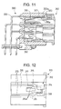
- a connector 330 on the male side located on the left side in Fig. 10 is a connector 330 on the male side made of synthetic resin.
- the connector 330 on the male side has male terminal fittings 332 that project toward a hood portion 331 in the front and confront the cavities 311 of the connector 310 on the female side.
- a pair of L-shaped detecting electrodes 333 connected to a not shown detecting circuit is attached to the connector 330 on the male side so as to extend along and project from the upper inner wall of a hood portion 331 of the connector 330.
- Both detecting electrodes 333 are such that distal ends 333a thereof projecting toward the hood portion 331 are inwardly bent, and such inwardly bent portions 333a are coupled to each other by an insulating engagement portion 335 that projects downward from the bent portions 333a.
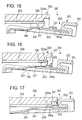
- the cover 320 of the connector 310 on the female side is set to the protecting position at which the contacts 316a of the short circuit electrode 316 are covered thereby as shown in Fig. 13. Accordingly, foreign matter such as dirt and dust is hard to deposit on the contacts 316a of the short circuit electrode 316.
- the cover 320 is slid rearward to the opening position to thereby expose the contacts 316a as shown in Fig. 14. As a result, the conditions of the contacts 316a can be inspected visibly.
- the cover 320 is moved back frontward to the protecting position as shown in Fig. 13.
- the contacts 316a of the short circuit electrode 316 can be protected and inspected easily as well as reliably, which in turn facilitates quality control.
- the connector 130 on the female side is inserted into the hood portion 331 of the connector 330 on the male side.
- the engagement portion 335 at the distal ends of the detecting electrodes 333 comes in contact with the upper surface of the short circuit electrode 316 to thereby elastically deform the short circuit electrode 316 together with the flexible lock piece 312 downward, so that the detecting electrodes 333 are kept distant from the short circuit electrode 316.
- the front end of the engagement portion 335 comes in contact with the front end of the protective plate portion 321.
- the engagement portion 335 pushes the cover 320 so that the cover 320 moves rearward with the detecting electrodes 333 not being in contact with the short circuit electrode 316.
- the cover 320 pushed by the engagement portion 335 moves to the opening position, which moves the engagement portion 335 to such a position as to be engageable with the engagement hole 317 of the short circuit electrode 316 and thereby releases the pushing of the engagement portion 335 toward the flexible lock piece 312 and the short circuit electrode 316. Accordingly, the flexible lock piece 312 and the short circuit electrode 316 return upward by the restitutive force, and as shown in Fig. 17, not only the engagement portion 335 gets engaged with the engagement hole 317, but also the distal ends 333a of the detecting electrodes 333 come in contact with the contacts 316a of the short circuit electrode 316.
- both connectors 310, 330 are locked so as not to be movable in such a direction as to be released from each other.
- both detecting electrodes 333 are short-circuited, which causes the detecting circuit to detect the short-circuiting and hence the correct locking of both connectors 310, 330.
Landscapes
- Details Of Connecting Devices For Male And Female Coupling (AREA)
Description
Claims (6)
- A lock detecting connector comprising:characterized in thattwo connector housings (310, 330) for engagement with each other, wherein at least a pair of lock detecting terminals (333) being provided in one (330) of the connector housings; anda short circuit terminal (316) in the other (310) of the connector housings, the short circuit terminal (316) serving to detect a locked state of both connector housings (310, 330) by way of short-circuiting the pair of lock detecting terminals (333) when both connector housings are engaged with each other completely,said other connector housing (310) has the short circuit terminal (316) exposed to the outside and has a cover (320) movable between a protecting position and an opening position, the protecting position being such a position as to allow the cover (320) to cover a contact portion (316a) of the short circuit terminal (316), the opening position being such a position as to allow the cover (320) to expose said contact portion (316a) of the short circuit terminal (316), andthe cover (320) is pushingly moved from the protecting position to the opening position by said one connector housing (330) when both connector housings (310, 330) are being connected.
- The lock detecting connector of claim 1, wherein the lock detecting terminals (333) are arranged along an inner wall surface of the one connector housing (330) accommodating the lock detecting terminals, and distal ends (333a) of the lock detecting terminals (333) are positioned backward with respect to an engagement opening of the one connector housing (330).
- The lock detecting connector as claimed in claim 1 or 2, wherein a flexible lock piece (312) is formed on said one connector housing (330) and an engagement portion (335) is formed on the other (310) of the connector housings, respectively; and wherein said short circuit terminal (316) is electrically connected to said lock detecting terminals (333) when said flexible lock piece (312) is engaged with said engagement portion (335).
- The lock detecting connector of anyone of claims 1 to 3, wherein said short circuit terminal (316) includes a leaf spring.
- The lock detecting connector of claim 3 or 4, wherein upon connection of said two connector housings (310, 330) said engagement portion (335) pushes said cover (320) from the protecting position to the opening position, wherein said short circuit terminal is elastically deformed by said engagement portion (335) such that said lock detecting terminals (333) are out of electrical contact with said short circuit terminal (316) unless said engagement portion (335) engages an engagement hole (317) in said one (310) connector housing when both connector housings (310, 330) are completely connected and said short circuit terminal (316) is elastically restored, so that electrical contact between said short circuit terminal (316) and said lock detecting terminals (333) takes place.
- The lock detecting connector of claim 5, wherein said engagement hole (317) is arranged in said short circuit terminal (316).
Priority Applications (1)
| Application Number | Priority Date | Filing Date | Title |
|---|---|---|---|
| EP98110335A EP0871253B1 (en) | 1993-12-06 | 1994-10-21 | Lock detection connector |
Applications Claiming Priority (6)
| Application Number | Priority Date | Filing Date | Title |
|---|---|---|---|
| JP5340033A JP2845112B2 (en) | 1993-12-06 | 1993-12-06 | connector |
| JP340033/93 | 1993-12-06 | ||
| JP5344331A JP2921378B2 (en) | 1993-12-16 | 1993-12-16 | Connector connection detection device |
| JP344331/93 | 1993-12-16 | ||
| JP1993074599U JP2594383Y2 (en) | 1993-12-27 | 1993-12-27 | Connector lock detection structure |
| JP74599/93U | 1993-12-27 |
Related Child Applications (1)
| Application Number | Title | Priority Date | Filing Date |
|---|---|---|---|
| EP98110335A Division EP0871253B1 (en) | 1993-12-06 | 1994-10-21 | Lock detection connector |
Publications (2)
| Publication Number | Publication Date |
|---|---|
| EP0657968A1 EP0657968A1 (en) | 1995-06-14 |
| EP0657968B1 true EP0657968B1 (en) | 1999-01-07 |
Family
ID=27301557
Family Applications (2)
| Application Number | Title | Priority Date | Filing Date |
|---|---|---|---|
| EP98110335A Expired - Lifetime EP0871253B1 (en) | 1993-12-06 | 1994-10-21 | Lock detection connector |
| EP94116642A Expired - Lifetime EP0657968B1 (en) | 1993-12-06 | 1994-10-21 | Lock detection connector |
Family Applications Before (1)
| Application Number | Title | Priority Date | Filing Date |
|---|---|---|---|
| EP98110335A Expired - Lifetime EP0871253B1 (en) | 1993-12-06 | 1994-10-21 | Lock detection connector |
Country Status (2)
| Country | Link |
|---|---|
| EP (2) | EP0871253B1 (en) |
| DE (2) | DE69429461T2 (en) |
Families Citing this family (12)
| Publication number | Priority date | Publication date | Assignee | Title |
|---|---|---|---|---|
| JP3264311B2 (en) * | 1995-09-25 | 2002-03-11 | 矢崎総業株式会社 | Connector connection detection device |
| JPH09139251A (en) * | 1995-11-14 | 1997-05-27 | Sumitomo Wiring Syst Ltd | Connector |
| US5913703A (en) * | 1996-04-24 | 1999-06-22 | Sumitomo Wiring Systems, Ltd. | Connector assembly with sequentially engageable housings |
| US7916803B2 (en) | 2003-04-10 | 2011-03-29 | Qualcomm Incorporated | Modified preamble structure for IEEE 802.11a extensions to allow for coexistence and interoperability between 802.11a devices and higher data rate, MIMO or otherwise extended devices |
| US8743837B2 (en) | 2003-04-10 | 2014-06-03 | Qualcomm Incorporated | Modified preamble structure for IEEE 802.11A extensions to allow for coexistence and interoperability between 802.11A devices and higher data rate, MIMO or otherwise extended devices |
| US7586884B2 (en) | 2003-08-15 | 2009-09-08 | Qualcomm Incorporated | Joint packet detection in wireless communication system with one or more receiver |
| JP4838241B2 (en) | 2004-05-27 | 2011-12-14 | クゥアルコム・インコーポレイテッド | Modified IEEE 802.11A for interoperation between IEEE 802.11A devices |
| JP5043515B2 (en) * | 2007-06-01 | 2012-10-10 | モレックス インコーポレイテド | Mating detection connector |
| JP5510346B2 (en) * | 2011-01-25 | 2014-06-04 | 住友電装株式会社 | connector |
| CN108923180B (en) * | 2018-06-29 | 2024-05-07 | 成都九鼎科技(集团)有限公司 | Plug auxiliary device for plug connector |
| JP7230739B2 (en) * | 2019-08-09 | 2023-03-01 | 住友電装株式会社 | connector |
| DE102023106977B3 (en) | 2023-03-21 | 2024-08-22 | Lisa Dräxlmaier GmbH | Plug with interlock contact, plug connection and method for producing a plug connection |
Family Cites Families (4)
| Publication number | Priority date | Publication date | Assignee | Title |
|---|---|---|---|---|
| GB1249805A (en) * | 1969-05-08 | 1971-10-13 | Vauxhall Motors Ltd | Electrical connectors |
| US4904196A (en) * | 1987-07-17 | 1990-02-27 | Yazaki Corporation | Releasable connector for electric circuits |
| US4917627A (en) * | 1989-04-28 | 1990-04-17 | Chrysler Corporation | Latch replacement kit |
| US5131865A (en) * | 1990-02-21 | 1992-07-21 | Yazaki Corporation | Connector apparatus with coupling detecting function |
-
1994
- 1994-10-21 DE DE69429461T patent/DE69429461T2/en not_active Expired - Fee Related
- 1994-10-21 DE DE69415786T patent/DE69415786T2/en not_active Expired - Fee Related
- 1994-10-21 EP EP98110335A patent/EP0871253B1/en not_active Expired - Lifetime
- 1994-10-21 EP EP94116642A patent/EP0657968B1/en not_active Expired - Lifetime
Also Published As
| Publication number | Publication date |
|---|---|
| EP0871253A3 (en) | 1999-02-03 |
| EP0871253A2 (en) | 1998-10-14 |
| DE69429461T2 (en) | 2002-06-27 |
| DE69429461D1 (en) | 2002-01-24 |
| EP0657968A1 (en) | 1995-06-14 |
| DE69415786T2 (en) | 1999-08-05 |
| DE69415786D1 (en) | 1999-02-18 |
| EP0871253B1 (en) | 2001-12-12 |
Similar Documents
| Publication | Publication Date | Title |
|---|---|---|
| US5562486A (en) | Lock detection connector | |
| JPH0620303Y2 (en) | Electrical connector coupling confirmation device | |
| EP0881712B1 (en) | Locked-state detecting system and lock connector comprising such system | |
| EP0645848B1 (en) | Connector engagement detecting device | |
| EP1054481B1 (en) | A connector | |
| US6638109B2 (en) | Connector with a side retainer | |
| US5984705A (en) | Connector | |
| JP3767779B2 (en) | Connector locking mechanism | |
| US6488524B2 (en) | Half-fitting prevention connector | |
| EP0418790B1 (en) | Perfect coupling confirming mechanism for an electric connector | |
| EP0734100A2 (en) | Electrical connector with terminal position assurance | |
| EP1104051B1 (en) | Connector | |
| KR100216000B1 (en) | Electrical connector assembly with a switch | |
| EP0657968B1 (en) | Lock detection connector | |
| EP1248328B1 (en) | Coupling Detector for Connector | |
| US6171130B1 (en) | Half-fitting prevention connector | |
| US20020025711A1 (en) | Connector fitting structure | |
| US5624275A (en) | Connector assembly with a connection detecting device | |
| JP2000164285A (en) | Connector having front holder | |
| EP1065757B1 (en) | Half-fitting detection connector | |
| US6422894B1 (en) | Connector fitting detection construction | |
| JPH09306582A (en) | Connector | |
| EP0975061A2 (en) | A watertight connector with inertial locking mechanism | |
| JP2894591B2 (en) | Terminal structure | |
| US5647762A (en) | Locking structure of short-circuit contact for connectors |
Legal Events
| Date | Code | Title | Description |
|---|---|---|---|
| PUAI | Public reference made under article 153(3) epc to a published international application that has entered the european phase |
Free format text: ORIGINAL CODE: 0009012 |
|
| AK | Designated contracting states |
Kind code of ref document: A1 Designated state(s): DE GB |
|
| 17P | Request for examination filed |
Effective date: 19950707 |
|
| 17Q | First examination report despatched |
Effective date: 19960221 |
|
| GRAG | Despatch of communication of intention to grant |
Free format text: ORIGINAL CODE: EPIDOS AGRA |
|
| GRAG | Despatch of communication of intention to grant |
Free format text: ORIGINAL CODE: EPIDOS AGRA |
|
| GRAH | Despatch of communication of intention to grant a patent |
Free format text: ORIGINAL CODE: EPIDOS IGRA |
|
| GRAH | Despatch of communication of intention to grant a patent |
Free format text: ORIGINAL CODE: EPIDOS IGRA |
|
| GRAA | (expected) grant |
Free format text: ORIGINAL CODE: 0009210 |
|
| AK | Designated contracting states |
Kind code of ref document: B1 Designated state(s): DE GB |
|
| REF | Corresponds to: |
Ref document number: 69415786 Country of ref document: DE Date of ref document: 19990218 |
|
| PLBE | No opposition filed within time limit |
Free format text: ORIGINAL CODE: 0009261 |
|
| STAA | Information on the status of an ep patent application or granted ep patent |
Free format text: STATUS: NO OPPOSITION FILED WITHIN TIME LIMIT |
|
| 26N | No opposition filed | ||
| PGFP | Annual fee paid to national office [announced via postgrant information from national office to epo] |
Ref country code: GB Payment date: 20001018 Year of fee payment: 7 |
|
| PG25 | Lapsed in a contracting state [announced via postgrant information from national office to epo] |
Ref country code: GB Free format text: LAPSE BECAUSE OF NON-PAYMENT OF DUE FEES Effective date: 20011021 |
|
| REG | Reference to a national code |
Ref country code: GB Ref legal event code: IF02 |
|
| GBPC | Gb: european patent ceased through non-payment of renewal fee |
Effective date: 20011021 |
|
| PGFP | Annual fee paid to national office [announced via postgrant information from national office to epo] |
Ref country code: DE Payment date: 20021024 Year of fee payment: 9 |
|
| PG25 | Lapsed in a contracting state [announced via postgrant information from national office to epo] |
Ref country code: DE Free format text: LAPSE BECAUSE OF NON-PAYMENT OF DUE FEES Effective date: 20040501 |