EP0657722B1 - A hot wire type air flowmeter - Google Patents
A hot wire type air flowmeter Download PDFInfo
- Publication number
- EP0657722B1 EP0657722B1 EP94308616A EP94308616A EP0657722B1 EP 0657722 B1 EP0657722 B1 EP 0657722B1 EP 94308616 A EP94308616 A EP 94308616A EP 94308616 A EP94308616 A EP 94308616A EP 0657722 B1 EP0657722 B1 EP 0657722B1
- Authority
- EP
- European Patent Office
- Prior art keywords
- output
- resistor
- wire type
- air
- air flowmeter
- Prior art date
- Legal status (The legal status is an assumption and is not a legal conclusion. Google has not performed a legal analysis and makes no representation as to the accuracy of the status listed.)
- Expired - Lifetime
Links
Images




Classifications
-
- G—PHYSICS
- G01—MEASURING; TESTING
- G01F—MEASURING VOLUME, VOLUME FLOW, MASS FLOW OR LIQUID LEVEL; METERING BY VOLUME
- G01F1/00—Measuring the volume flow or mass flow of fluid or fluent solid material wherein the fluid passes through a meter in a continuous flow
- G01F1/68—Measuring the volume flow or mass flow of fluid or fluent solid material wherein the fluid passes through a meter in a continuous flow by using thermal effects
-
- G—PHYSICS
- G01—MEASURING; TESTING
- G01F—MEASURING VOLUME, VOLUME FLOW, MASS FLOW OR LIQUID LEVEL; METERING BY VOLUME
- G01F1/00—Measuring the volume flow or mass flow of fluid or fluent solid material wherein the fluid passes through a meter in a continuous flow
- G01F1/68—Measuring the volume flow or mass flow of fluid or fluent solid material wherein the fluid passes through a meter in a continuous flow by using thermal effects
- G01F1/696—Circuits therefor, e.g. constant-current flow meters
- G01F1/698—Feedback or rebalancing circuits, e.g. self heated constant temperature flowmeters
-
- G—PHYSICS
- G01—MEASURING; TESTING
- G01F—MEASURING VOLUME, VOLUME FLOW, MASS FLOW OR LIQUID LEVEL; METERING BY VOLUME
- G01F1/00—Measuring the volume flow or mass flow of fluid or fluent solid material wherein the fluid passes through a meter in a continuous flow
- G01F1/68—Measuring the volume flow or mass flow of fluid or fluent solid material wherein the fluid passes through a meter in a continuous flow by using thermal effects
- G01F1/684—Structural arrangements; Mounting of elements, e.g. in relation to fluid flow
-
- G—PHYSICS
- G01—MEASURING; TESTING
- G01F—MEASURING VOLUME, VOLUME FLOW, MASS FLOW OR LIQUID LEVEL; METERING BY VOLUME
- G01F1/00—Measuring the volume flow or mass flow of fluid or fluent solid material wherein the fluid passes through a meter in a continuous flow
- G01F1/68—Measuring the volume flow or mass flow of fluid or fluent solid material wherein the fluid passes through a meter in a continuous flow by using thermal effects
- G01F1/684—Structural arrangements; Mounting of elements, e.g. in relation to fluid flow
- G01F1/6842—Structural arrangements; Mounting of elements, e.g. in relation to fluid flow with means for influencing the fluid flow
-
- G—PHYSICS
- G01—MEASURING; TESTING
- G01F—MEASURING VOLUME, VOLUME FLOW, MASS FLOW OR LIQUID LEVEL; METERING BY VOLUME
- G01F1/00—Measuring the volume flow or mass flow of fluid or fluent solid material wherein the fluid passes through a meter in a continuous flow
- G01F1/68—Measuring the volume flow or mass flow of fluid or fluent solid material wherein the fluid passes through a meter in a continuous flow by using thermal effects
- G01F1/696—Circuits therefor, e.g. constant-current flow meters
Definitions
- the present invention relates to an air flowmeter having a hot wire type resistor for detecting air flow rates to control a vehicle engine.
- the output span of an air flowmeter is set by adjusting resistors connected to the current detecting terminal of a hot wire and the zero point is adjusted by changing the standard input voltage of a differential amplifier.
- US 5,237,868 discloses a hot wire type air flowmeter having a drive circuit and an output adjusting circuit comprising a subtractor having an input terminal applied with an output of the drive circuit, another input terminal applied with a constant voltage reference and an output supplied to a non-inverting amplifier.
- the zero adjustment and the output span adjustment are not independent and mutually interfere.
- JP-A-57184923 disclosing a subtractor to which two variable signals are applied.
- the present invention has been achieved in consideration of the above-described problems, and is aimed at providing an improved hot wire type air flowmeter.
- the current flowing in the hot wire type resistor is converted to a voltage signal by a standard resistor.
- the output span of the voltage signal is adjusted so as to take the preset gradient by a non-inverting amplifier.
- a voltage follower is connected between a voltage reference source and a subtracter so as to set the zero point to the preset voltage.
- Fig. 1 shows an embodiment of the present invention.
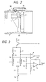
- Fig. 2 shows a sectional view of an air flowmeter by the embodiment of the present invention.
- Fig. 3 shows a conventional air flowmeter.
- Fig. 4 shows a flow chart of an adjustment method in the present invention.
- Fig. 5 shows a circuit for an air flowmeter not forming part of the invention.
- Fig. 6 shows a further embodiment of the present invention.
- Fig. 7 shows yet another embodiment of the present invention.
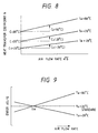
- Fig. 8 shows the relation between the heat transfer coefficient and the air flow rate.
- Fig. 9 shows the relation between the error induced by temperature change and the air flow rate.
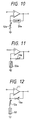
- Fig.10 shows are example of an amplifier capable of compensating temperature dependency.
- Fig.11 shows another example of an amplifier capable of compensating temperature dependency.
- Fig.12 shows a further example of an amplifier capable of compensating temperature dependency.
- Fig.13 shows yet another example of an amplifier capable of compensating temperature dependency.
- Fig.14 shows a sectional view of an air flowmeter in another embodiment of the present invention.
- FIG. 1 is a drawing showing the embodiment of the present invention
- Figure 2 is a sectional view of an air flowmeter by the present invention.
- a hot wire type resistor 1 and a thermistor type thermometer 2 are provided in an air path 30.
- a standard resistor 4 converts the current flowing in the hot wire type resistor 1 to a voltage signal and composes a bridge circuit together with resistors 5, 6 and 7.
- the bridge circuit controls a transistor 3 via differential amplifiers 8 and 9 by using the hot wire type resistor 1 and the thermistor type resistor 2 so that the hot wire type resistor 1 keeps the predetermined temperature corresponding to the air temperature. Therefore, the current Ih flowing in the standard resistor 4 changes in accordance with air flow rate Q as shown by Eq.1 when the temperature of the hot wire type resistor 1 is controlled as a constant. That is, the terminal voltage Vo of the standard resistor 4 changes in accordance with the air flow rate Q as shown by Eq.2. Then, the hot wire type resistor 1 is controlled by the drive circuit 102.
- Ih 2 ⁇ Rh ( A + B Q ) ( Th - Ta ) where,
- FIG. 3 shows a conventional circuit for absorbing the scatter.
- a resistor 4a connected to a resistor 4 for detecting the current flowing in the hot wire type resistor 1 is adjusted so that the output span is set as the predetermined value.
- the zero point is adjusted by feeding the standard voltage input into a differential amplifier 74 and changing the resistance values of resistors 76 and 78.
- the relation between the terminal voltage Vo and the output voltage Vout is expressed by Eq. 3.
- Vout [1+( R77 + R75 ) xR75 /( R77 ⁇ R75 + R75 ⁇ R76 + R76 ⁇ R77 )] x [ R73 /( R73 + R72 )] xVo -[( R78 ⁇ R75 )/( R77 ⁇ R78 + R78 ⁇ R76 + R76 ⁇ R77 )] xVref
- the embodiment comprises a non-inverting amplifier composed of a differential amplifier 11 and resistors 12 and 13, a voltage follower formed by a differential amplifier 21, an output thereof being fed back to a negative input of said differential amplifier 21, and the negative input of the differential amplifier 21 is input to a subtractor formed by a differential amplifier 18 and resistors 14, 15, 16 and 17.
- These circuits are formed on a substrate 70 and mounted in a case 80.
- the relation between the terminal voltage Vo and the output voltage Vout is expressed by Eq.4.
- Vout [( R12 + R13 )/ R12 ] ⁇ Vo -[ R20 /( R19 + R20 )] ⁇ Vref
- the terminal voltage Vo of the standard resistor at an optional flow rate Q1 is measured and the measured output value is expressed as Vo1.
- the terminal voltage Vo of the standard resistor at an optional flow rate Q2 different from Q1 is measured and the measured value is marked with Vo2.
- the required output values at the flow rates Q1 and Q2 are set as Vo1 and Vo2
- the relations between R12 and R13, and R19 and R20 are expressed by Eqs.5 and 6, respectively, from Eq.4.
- the zero and the output span adjustment can be executed, respectively, by only adjusting resistors R12, R13, R19 and R20 without continuously flowing air since the resistance values to be adjusted can be uniquely obtained by calculations if only the terminal voltages Vo1 and Vo2 at the flow rates Q1 and Q2 are measured.
- Fig. 5 shows a circuit for an air flowmeter not forming part of the invention having the non-inverting amplifier 11, the subtracter 18 and the voltage follower 21.
- Vout [( R12 + R13 )/ R12 ] ⁇ [ Vo - R20 /( R19 + R20 ) ⁇ Vref ]
- the zero and the output span adjustment can be executed by adjusting firstly the zero point and secondly the output span.
- the circuits for the zero and the output span adjustment are provided before an output converting circuit.
- the ouotput converting circuit 40 converts the output voltage to a frequency output or a current output.
- the zero point and the output span adjustment can be made; also adjustments for the frequency output and the current output may be made.
- a resistor 50 having a temperature coefficient different from the other resistors is provided in the negative feedback loop of the non-inverting. amplifier and installed at a position which is exposed to suction air.
- the voltage source circuit for Vref has the temperature dependency for compensating the changes of the output voltage Vout caused by the changes of suction air temperature at a flow rate Qa.
- the conventional circuit can compensate for the change of the output at only one point of the flow rate Qa and can not compensate the output change through the whole range of flow rate. Then, the error of ouptut dQ/Q changes as shown in Fig. 9.
- the output change induced by the air temperature change is compensated by providing a resistor having a temperature coefficient which compensates the heat transfer coefficient change due to the air temperature dependency, as well as the flow rate change.
- the changes of the zero point and the output span can be compensated by combining such a resistor and the conventional circuit.
- the embodiments shown by Figs. 10 and 11 comprise a variable resistor 50a having a temperature coefficient different from the other variable resistors 12a or 13a.
- a fixed resistor 50 having a temperature coefficient different from the other variable resistors 12a or 13a is provided between the negative input terminal of the differential amplifier 11 and earth potential.
- the resistor 50 having the temperature coefficient different from the other resistors is made by a monolithic resistor and formed in an IC.
- An air flowmeter made by this embodiment has a worse accuracy, but can be made less expensively. The IC and other elements are protected and the reliability of the air flowmeter is improved.
Landscapes
- Physics & Mathematics (AREA)
- Fluid Mechanics (AREA)
- General Physics & Mathematics (AREA)
- Measuring Volume Flow (AREA)
- Details Of Flowmeters (AREA)
Description
- The present invention relates to an air flowmeter having a hot wire type resistor for detecting air flow rates to control a vehicle engine.
- In the conventional equipment, as described by Japanese Patent Application Laid-Open 184923/1982, the output span of an air flowmeter is set by adjusting resistors connected to the current detecting terminal of a hot wire and the zero point is adjusted by changing the standard input voltage of a differential amplifier.
- It is difficult in the conventional techniques to adjust the output of a flowmeter since the zero adjustment of an air flowmeter output changes also the output span due to temperature differences in every hot wire product and convergence operations by alternatively adjusting the zero point and the output span are needed to fix the zero point and the output span to each target value. That is, the conventional techniques have the problem that the zero adjustment and the output span adjustment can not be made independently without mutual interferences. Further, the conventional techniques cannot give enough compensations to temperature changes since the output of an air flowmeter cannot be compensated over the whole range of flow rates and such output temperature compensation is conventionally possible at one point only of flow rate.
- US 5,237,868 discloses a hot wire type air flowmeter having a drive circuit and an output adjusting circuit comprising a subtractor having an input terminal applied with an output of the drive circuit, another input terminal applied with a constant voltage reference and an output supplied to a non-inverting amplifier. The zero adjustment and the output span adjustment are not independent and mutually interfere.
- A further hot wire type air flowmeter is disclosed in JP-A-57184923 disclosing a subtractor to which two variable signals are applied.
- The present invention has been achieved in consideration of the above-described problems, and is aimed at providing an improved hot wire type air flowmeter.
- According to this invention there is provided a hot wire type air flowmeter as claimed in
claim 1 herein. - The current flowing in the hot wire type resistor is converted to a voltage signal by a standard resistor. The output span of the voltage signal is adjusted so as to take the preset gradient by a non-inverting amplifier. A voltage follower is connected between a voltage reference source and a subtracter so as to set the zero point to the preset voltage.
- Fig. 1 shows an embodiment of the present invention.
- Fig. 2 shows a sectional view of an air flowmeter by the embodiment of the present invention.
- Fig. 3 shows a conventional air flowmeter.
- Fig. 4 shows a flow chart of an adjustment method in the present invention.
- Fig. 5 shows a circuit for an air flowmeter not forming part of the invention.
- Fig. 6 shows a further embodiment of the present invention.
- Fig. 7 shows yet another embodiment of the present invention.
- Fig. 8 shows the relation between the heat transfer coefficient and the air flow rate.
- Fig. 9 shows the relation between the error induced by temperature change and the air flow rate.
- Fig.10 shows are example of an amplifier capable of compensating temperature dependency.
- Fig.11 shows another example of an amplifier capable of compensating temperature dependency.
- Fig.12 shows a further example of an amplifier capable of compensating temperature dependency.
- Fig.13 shows yet another example of an amplifier capable of compensating temperature dependency.
- Fig.14 shows a sectional view of an air flowmeter in another embodiment of the present invention.
- Hereinafter, details of the present invention are explained based on embodiments referring to drawings. Figure 1 is a drawing showing the embodiment of the present invention and Figure 2 is a sectional view of an air flowmeter by the present invention. By using Figs.1 and 2, the fundamental operations and constitution of the present invention are explained. A hot
wire type resistor 1 and athermistor type thermometer 2 are provided in anair path 30. Astandard resistor 4 converts the current flowing in the hotwire type resistor 1 to a voltage signal and composes a bridge circuit together withresistors 5, 6 and 7. The bridge circuit controls atransistor 3 viadifferential amplifiers wire type resistor 1 and thethermistor type resistor 2 so that the hotwire type resistor 1 keeps the predetermined temperature corresponding to the air temperature. Therefore, the current Ih flowing in thestandard resistor 4 changes in accordance with air flow rate Q as shown by Eq.1 when the temperature of the hotwire type resistor 1 is controlled as a constant. That is, the terminal voltage Vo of thestandard resistor 4 changes in accordance with the air flow rate Q as shown by Eq.2. Then, the hotwire type resistor 1 is controlled by thedrive circuit 102. - Rh :
- the resistance value of the hot wire type resistor in the heating state,
- A, B :
- constants of the hot wire type resistor,
- Th :
- the temperature of the hot wire type resistor in the heating state, and
- Ta :
- the air temperature.
- R4 :
- the resistance value of the
standard resistor 4. - Individual scatter of the terminal voltage Vo is induced by productive scatter of hot wire type resistors. In order to absorb the scatter, an output adjusting
circuit 101 is provided. Figure 3 shows a conventional circuit for absorbing the scatter. In the conventional circuit, aresistor 4a connected to aresistor 4 for detecting the current flowing in the hotwire type resistor 1 is adjusted so that the output span is set as the predetermined value. By this method, the temperature of the hotwire type resistor 1 can not be kept constant, which makes the temperature characteristics of the flowmeter worse. The zero point is adjusted by feeding the standard voltage input into adifferential amplifier 74 and changing the resistance values ofresistors - Vref :
- the standard voltage,
- R72 :
- the resistance value of
resistor 72, - R73 :
- the resistance value of
resistor 73, - R74 :
- the resistance value of
resistor 74, - R75 :
- the resistance value of
resistor 75, - R76 :
- the resistance value of
resistor 76, - R77 :
- the resistance value of
resistor 77, and - R78 :
- the resistance value of
resistor 78. - From Eq. 3, if the zero point is adjusted by resistors for the zero adjustment, the output span is also changed.
- On the other hand, the embodiment comprises a non-inverting amplifier composed of a
differential amplifier 11 andresistors differential amplifier 21, an output thereof being fed back to a negative input of saiddifferential amplifier 21, and the negative input of thedifferential amplifier 21 is input to a subtractor formed by adifferential amplifier 18 andresistors substrate 70 and mounted in acase 80. In the embodiment, the relation between the terminal voltage Vo and the output voltage Vout is expressed by Eq.4. - R12 :
- the resistance value of
resistor 12, - R13 :
- the resistance value of
resistor 13, - R19 :
- the resistance value of
resistor 19, and - R20 :
- the resistance value of
resistor 20. - In making the adjustment using flowing air, resistors are adjusted so that the output Vout is set to the predetermined value and Vout is measured. However, this method consumes wastefully energy since air needs to be continuously flowed during the adjustment. A method in which it is not necessary to continuously flow air during the adjustment is explained by a flow chart of adjustment procedures shown by Fig.4.
- At first, the terminal voltage Vo of the standard resistor at an optional flow rate Q1 is measured and the measured output value is expressed as Vo1. Secondly, the terminal voltage Vo of the standard resistor at an optional flow rate Q2 different from Q1 is measured and the measured value is marked with Vo2. Then, if the required output values at the flow rates Q1 and Q2 are set as Vo1 and Vo2, the relations between R12 and R13, and R19 and R20 are expressed by Eqs.5 and 6, respectively, from Eq.4.
- As proven from Eqs.5 and 6, the zero and the output span adjustment can be executed, respectively, by only adjusting resistors R12, R13, R19 and R20 without continuously flowing air since the resistance values to be adjusted can be uniquely obtained by calculations if only the terminal voltages Vo1 and Vo2 at the flow rates Q1 and Q2 are measured.
- Fig. 5 shows a circuit for an air flowmeter not forming part of the invention having the
non-inverting amplifier 11, thesubtracter 18 and thevoltage follower 21. The relation between Vo and Vout in this case is shown below. - As proven from Eq.7 in this case the zero and the output span adjustment can be executed by adjusting firstly the zero point and secondly the output span.
- In the embodiment shown in Fig. 6, the circuits for the zero and the output span adjustment are provided before an output converting circuit. The
ouotput converting circuit 40 converts the output voltage to a frequency output or a current output. By this embodiment, the zero point and the output span adjustment can be made; also adjustments for the frequency output and the current output may be made. - In the embodiment shown in Fig. 7, a
resistor 50 having a temperature coefficient different from the other resistors is provided in the negative feedback loop of the non-inverting. amplifier and installed at a position which is exposed to suction air. - In the conventional circuit for the air flowmeter the voltage source circuit for Vref has the temperature dependency for compensating the changes of the output voltage Vout caused by the changes of suction air temperature at a flow rate Qa. However, the Vout is not directly proportional to the change of flow rate through the whole range of flow rate. The reason for this is because the heat transfer coefficient h is expressed by Eq. 8 and coefficients C1 and C2 of the equation depend on the suction air temperature as shown by Fig. 8.
- Therefore, the conventional circuit can compensate for the change of the output at only one point of the flow rate Qa and can not compensate the output change through the whole range of flow rate. Then, the error of ouptut dQ/Q changes as shown in Fig. 9. In the present invention, the output change induced by the air temperature change is compensated by providing a resistor having a temperature coefficient which compensates the heat transfer coefficient change due to the air temperature dependency, as well as the flow rate change. The changes of the zero point and the output span can be compensated by combining such a resistor and the conventional circuit.
- The embodiments shown by Figs. 10 and 11 comprise a
variable resistor 50a having a temperature coefficient different from the othervariable resistors 12a or 13a. In the embodiment shown in Fig. 12, a fixedresistor 50 having a temperature coefficient different from the othervariable resistors 12a or 13a is provided between the negative input terminal of thedifferential amplifier 11 and earth potential. In the embodiment shown by Fig. 13, theresistor 50 having the temperature coefficient different from the other resistors is made by a monolithic resistor and formed in an IC. An air flowmeter made by this embodiment has a worse accuracy, but can be made less expensively. The IC and other elements are protected and the reliability of the air flowmeter is improved. By adopting such a structure, as shown in Fig. 14, an air flowmeter having a substrate in which the resistor having a temperature coefficient different from other resistors, or the IC including the resistor having the temperature coefficient different from other resistors, is provided which is wholly and directly exposed in the suction air flow so that the substrate is at substantially the same temperature as the suction air.
Claims (4)
- Air flowmeter having a hot-wire type resistor (1) for detecting air flow rates, a thermistor (2) for detecting the temperature around said hot-wire type resistor (1), a drive circuit (102) for controlling the temperature of said hot wire type resistor (1) and for outputting electric signals indicative thereof and an output adjusting circuit (101) for adjusting said electric signals having a subtractor (14-18) receiving an output of an adjustable voltage reference means (19-21), wherein said output adjusting circuit (101) performs a zero point adjustment and a span adjustment for said outputted electric signals by using said subtractor (14-18) having an input terminal applied with said electric outputted signals through an adjustable non-inverting amplifier (11-13) and another input terminal applied with an output signal from said voltage reference means (19-21), wherein said voltage reference means (19-21) comprises a differential amplifier (21), in which an output signal thereof is fed back to a negative input of said differential amplifier (21), and has a composition such that a divided reference voltage is outputted to said another input terminal through said differential amplifier (21), and wherein said voltage reference means (19-21) is used for said zero point adjustment and said non-inverting amplifier (11-13) is used for said span adjustment for said outputted electric signals.
- Air flowmeter according to claim 1, wherein said differential amplifier (21) is connected to a negative input of the subtractor (14-18) via a resistor (16).
- Air flowmeter according to any preceding claim, wherein the non-inverting amplifier (11-13) inclues two resistors (12a, 13a, 50, 50a) of different temperature coefficients, one of which is connected between an output terminal and an input terminal of the non-inverting amplifier (11-13).
- Air flowmeter according to claim 4, wherein at least one (50) of said two resistors is installed in an air path.
Applications Claiming Priority (3)
| Application Number | Priority Date | Filing Date | Title |
|---|---|---|---|
| JP30621693 | 1993-12-07 | ||
| JP30621693A JP3150510B2 (en) | 1993-12-07 | 1993-12-07 | Heating resistance type air flow meter |
| JP306216/93 | 1993-12-07 |
Publications (3)
| Publication Number | Publication Date |
|---|---|
| EP0657722A2 EP0657722A2 (en) | 1995-06-14 |
| EP0657722A3 EP0657722A3 (en) | 1996-01-10 |
| EP0657722B1 true EP0657722B1 (en) | 2002-05-02 |
Family
ID=17954392
Family Applications (1)
| Application Number | Title | Priority Date | Filing Date |
|---|---|---|---|
| EP94308616A Expired - Lifetime EP0657722B1 (en) | 1993-12-07 | 1994-11-22 | A hot wire type air flowmeter |
Country Status (5)
| Country | Link |
|---|---|
| US (1) | US5537871A (en) |
| EP (1) | EP0657722B1 (en) |
| JP (1) | JP3150510B2 (en) |
| KR (1) | KR100318039B1 (en) |
| DE (1) | DE69430508T2 (en) |
Families Citing this family (16)
| Publication number | Priority date | Publication date | Assignee | Title |
|---|---|---|---|---|
| JP3609148B2 (en) * | 1995-05-12 | 2005-01-12 | 株式会社日立製作所 | Heat resistance air flow meter |
| JP3323745B2 (en) | 1996-07-25 | 2002-09-09 | 株式会社日立製作所 | Characteristic adjustment means of physical quantity detection device and heating resistance type air flow device |
| JP3300615B2 (en) * | 1996-11-19 | 2002-07-08 | 株式会社日立製作所 | Ratiometric output type heating resistor type air flow meter, heating resistor type air flow meter and engine control device |
| DE19749524C2 (en) * | 1997-11-08 | 1999-10-21 | Reisland Martin Ulrich | Device for measuring the volume flow of a flowing medium |
| JP3394908B2 (en) * | 1998-06-03 | 2003-04-07 | 三菱電機株式会社 | Thermal flow sensor |
| JP4390160B2 (en) | 1998-06-26 | 2009-12-24 | 住友電気工業株式会社 | Batch coating die apparatus for manufacturing a split type optical fiber ribbon and manufacturing method |
| US6512412B2 (en) | 1999-02-16 | 2003-01-28 | Micron Technology, Inc. | Temperature compensated reference voltage circuit |
| DE10003436B4 (en) * | 1999-02-18 | 2009-08-13 | Ifm Electronic Gmbh | Heat transfer control and / or meter |
| NL1014797C2 (en) * | 2000-03-30 | 2001-10-02 | Berkin Bv | Mass flow meter. |
| DE10026002A1 (en) * | 2000-05-25 | 2001-12-06 | Bosch Gmbh Robert | Device for monitoring a fan in a gas heater |
| KR20020080137A (en) * | 2001-04-11 | 2002-10-23 | 주식회사 쎄스텍 | Sensor for detecting the mass flow rate and device and method for controlling mass flow rate using it |
| JP4608843B2 (en) * | 2002-02-19 | 2011-01-12 | 株式会社デンソー | Flow measuring device |
| US7298280B2 (en) * | 2003-06-06 | 2007-11-20 | Ameriflo Inc. | Lighted fluid flow indication apparatus |
| US7051599B2 (en) * | 2004-11-01 | 2006-05-30 | Board Of Trustees Operating Michigan State University | Thermal transient anemometer having sensing cell assembly |
| US9494470B2 (en) | 2014-03-20 | 2016-11-15 | Varian Semiconductor Equipment Associates, Inc. | Thermistor based measurement system |
| CN104238608A (en) * | 2014-09-09 | 2014-12-24 | 江苏大学 | Full-frequency-domain direct current voltage signal reduction voltage amplifying circuit |
Citations (3)
| Publication number | Priority date | Publication date | Assignee | Title |
|---|---|---|---|---|
| JPS57184923A (en) * | 1981-04-30 | 1982-11-13 | Hitachi Ltd | Hot-wire type flowmeter |
| EP0522496A2 (en) * | 1991-07-08 | 1993-01-13 | Nippondenso Co., Ltd. | Thermal type flowmeter |
| US5237868A (en) * | 1990-12-28 | 1993-08-24 | Mitsubishi Denki Kabushiki Kaisha | Thermal flow sensor for compensating gradient of flow rate characteristics |
Family Cites Families (5)
| Publication number | Priority date | Publication date | Assignee | Title |
|---|---|---|---|---|
| JPS56112610A (en) * | 1980-02-12 | 1981-09-05 | Oval Eng Co Ltd | Measuring device for gas |
| JPS5722563A (en) * | 1980-07-15 | 1982-02-05 | Hitachi Ltd | Sucked air flowmeter for internal combustion engine |
| JPS60151517A (en) * | 1984-01-18 | 1985-08-09 | Nippon Soken Inc | Semiconductor type flow rate detector |
| US5141021A (en) * | 1991-09-06 | 1992-08-25 | Stec Inc. | Mass flow meter and mass flow controller |
| GB9123893D0 (en) * | 1991-11-11 | 1992-01-02 | Lucas Ind Plc | Hot wire flow rate measuring circuit |
-
1993
- 1993-12-07 JP JP30621693A patent/JP3150510B2/en not_active Expired - Lifetime
-
1994
- 1994-11-01 KR KR1019940028467A patent/KR100318039B1/en not_active Expired - Fee Related
- 1994-11-22 EP EP94308616A patent/EP0657722B1/en not_active Expired - Lifetime
- 1994-11-22 DE DE69430508T patent/DE69430508T2/en not_active Expired - Fee Related
- 1994-12-06 US US08/354,036 patent/US5537871A/en not_active Expired - Lifetime
Patent Citations (3)
| Publication number | Priority date | Publication date | Assignee | Title |
|---|---|---|---|---|
| JPS57184923A (en) * | 1981-04-30 | 1982-11-13 | Hitachi Ltd | Hot-wire type flowmeter |
| US5237868A (en) * | 1990-12-28 | 1993-08-24 | Mitsubishi Denki Kabushiki Kaisha | Thermal flow sensor for compensating gradient of flow rate characteristics |
| EP0522496A2 (en) * | 1991-07-08 | 1993-01-13 | Nippondenso Co., Ltd. | Thermal type flowmeter |
Also Published As
| Publication number | Publication date |
|---|---|
| US5537871A (en) | 1996-07-23 |
| JPH07159214A (en) | 1995-06-23 |
| KR100318039B1 (en) | 2002-04-06 |
| KR950019643A (en) | 1995-07-24 |
| DE69430508D1 (en) | 2002-06-06 |
| EP0657722A3 (en) | 1996-01-10 |
| DE69430508T2 (en) | 2002-11-14 |
| JP3150510B2 (en) | 2001-03-26 |
| EP0657722A2 (en) | 1995-06-14 |
Similar Documents
| Publication | Publication Date | Title |
|---|---|---|
| EP0108409B1 (en) | Temperature compensating voltage generator circuit | |
| US5537871A (en) | Hot wire type air flowmeter | |
| US4984460A (en) | Mass flowmeter | |
| EP0147573B1 (en) | Air flow meter circuit with temperature compensation circuit | |
| US5053692A (en) | Temperature dependent power supply for use with a bridge transducer | |
| EP0543056B1 (en) | Temperature dependent current generator | |
| US4593241A (en) | Hall generator circuit with temperature compensation | |
| US4532468A (en) | Temperature-compensating voltage generator circuit | |
| KR100398492B1 (en) | Air flow meter and air flow detection method | |
| US5220831A (en) | Closed loop temperature compensation for accelerometer current scale factor | |
| US4800759A (en) | Semiconductor pressure converter | |
| US4947057A (en) | Adjustable temperature variable output signal circuit | |
| US5460040A (en) | Thermosetting flowmeter | |
| EP1610101B1 (en) | Heating resistor type air flow meter | |
| JPH07502828A (en) | Temperature compensation circuit using a single temperature compensation element | |
| EP0323005B1 (en) | Hot wire type air flow meter | |
| US5824895A (en) | Air flow meter of a heating resistor type | |
| US5237868A (en) | Thermal flow sensor for compensating gradient of flow rate characteristics | |
| US6038921A (en) | Mass flow sensor system for fast temperature sensing responses | |
| US4882767A (en) | Stabilized transmitter | |
| US20240097621A1 (en) | Compensation of thermally induced voltage errors | |
| CN87106874A (en) | Transducer with improved span adjuster | |
| US7040159B2 (en) | Air meter | |
| US4114085A (en) | Method of improving the temperature stability of a voltage source, and a stabilized voltage source for carrying out the method | |
| US7140246B2 (en) | Frequency output type hot-wire flow meter |
Legal Events
| Date | Code | Title | Description |
|---|---|---|---|
| PUAI | Public reference made under article 153(3) epc to a published international application that has entered the european phase |
Free format text: ORIGINAL CODE: 0009012 |
|
| 17P | Request for examination filed |
Effective date: 19941205 |
|
| AK | Designated contracting states |
Kind code of ref document: A2 Designated state(s): DE GB IT |
|
| PUAL | Search report despatched |
Free format text: ORIGINAL CODE: 0009013 |
|
| AK | Designated contracting states |
Kind code of ref document: A3 Designated state(s): DE GB IT |
|
| 17Q | First examination report despatched |
Effective date: 19961205 |
|
| GRAG | Despatch of communication of intention to grant |
Free format text: ORIGINAL CODE: EPIDOS AGRA |
|
| GRAG | Despatch of communication of intention to grant |
Free format text: ORIGINAL CODE: EPIDOS AGRA |
|
| GRAG | Despatch of communication of intention to grant |
Free format text: ORIGINAL CODE: EPIDOS AGRA |
|
| GRAH | Despatch of communication of intention to grant a patent |
Free format text: ORIGINAL CODE: EPIDOS IGRA |
|
| GRAH | Despatch of communication of intention to grant a patent |
Free format text: ORIGINAL CODE: EPIDOS IGRA |
|
| REG | Reference to a national code |
Ref country code: GB Ref legal event code: IF02 |
|
| GRAA | (expected) grant |
Free format text: ORIGINAL CODE: 0009210 |
|
| RAP1 | Party data changed (applicant data changed or rights of an application transferred) |
Owner name: HITACHI CAR ENGINEERING CO., LTD. Owner name: HITACHI, LTD. |
|
| AK | Designated contracting states |
Kind code of ref document: B1 Designated state(s): DE GB IT |
|
| REG | Reference to a national code |
Ref country code: GB Ref legal event code: FG4D |
|
| REF | Corresponds to: |
Ref document number: 69430508 Country of ref document: DE Date of ref document: 20020606 |
|
| PLBE | No opposition filed within time limit |
Free format text: ORIGINAL CODE: 0009261 |
|
| STAA | Information on the status of an ep patent application or granted ep patent |
Free format text: STATUS: NO OPPOSITION FILED WITHIN TIME LIMIT |
|
| 26N | No opposition filed |
Effective date: 20030204 |
|
| PGFP | Annual fee paid to national office [announced via postgrant information from national office to epo] |
Ref country code: DE Payment date: 20081126 Year of fee payment: 15 |
|
| PGFP | Annual fee paid to national office [announced via postgrant information from national office to epo] |
Ref country code: IT Payment date: 20081024 Year of fee payment: 15 |
|
| PGFP | Annual fee paid to national office [announced via postgrant information from national office to epo] |
Ref country code: GB Payment date: 20081021 Year of fee payment: 15 |
|
| GBPC | Gb: european patent ceased through non-payment of renewal fee |
Effective date: 20091122 |
|
| PG25 | Lapsed in a contracting state [announced via postgrant information from national office to epo] |
Ref country code: DE Free format text: LAPSE BECAUSE OF NON-PAYMENT OF DUE FEES Effective date: 20100601 |
|
| PG25 | Lapsed in a contracting state [announced via postgrant information from national office to epo] |
Ref country code: GB Free format text: LAPSE BECAUSE OF NON-PAYMENT OF DUE FEES Effective date: 20091122 |
|
| PG25 | Lapsed in a contracting state [announced via postgrant information from national office to epo] |
Ref country code: IT Free format text: LAPSE BECAUSE OF NON-PAYMENT OF DUE FEES Effective date: 20091122 |