EP0657641A2 - Rotary distributor type fuel injection pump - Google Patents
Rotary distributor type fuel injection pump Download PDFInfo
- Publication number
- EP0657641A2 EP0657641A2 EP94630046A EP94630046A EP0657641A2 EP 0657641 A2 EP0657641 A2 EP 0657641A2 EP 94630046 A EP94630046 A EP 94630046A EP 94630046 A EP94630046 A EP 94630046A EP 0657641 A2 EP0657641 A2 EP 0657641A2
- Authority
- EP
- European Patent Office
- Prior art keywords
- rotor
- distributor
- pump
- valve
- bore
- Prior art date
- Legal status (The legal status is an assumption and is not a legal conclusion. Google has not performed a legal analysis and makes no representation as to the accuracy of the status listed.)
- Withdrawn
Links
- 239000000446 fuel Substances 0.000 title claims abstract description 97
- 238000002347 injection Methods 0.000 title claims abstract description 49
- 239000007924 injection Substances 0.000 title claims abstract description 49
- 238000005086 pumping Methods 0.000 claims abstract description 85
- 238000007789 sealing Methods 0.000 claims description 34
- 230000002093 peripheral effect Effects 0.000 claims description 17
- 230000008878 coupling Effects 0.000 claims description 10
- 238000010168 coupling process Methods 0.000 claims description 10
- 238000005859 coupling reaction Methods 0.000 claims description 10
- 230000004323 axial length Effects 0.000 claims description 5
- 238000002955 isolation Methods 0.000 claims description 3
- 238000013016 damping Methods 0.000 claims 1
- 230000000694 effects Effects 0.000 claims 1
- 238000013022 venting Methods 0.000 claims 1
- 230000006835 compression Effects 0.000 abstract description 6
- 238000007906 compression Methods 0.000 abstract description 6
- 238000005461 lubrication Methods 0.000 description 4
- OKKJLVBELUTLKV-UHFFFAOYSA-N Methanol Chemical compound OC OKKJLVBELUTLKV-UHFFFAOYSA-N 0.000 description 3
- 230000001133 acceleration Effects 0.000 description 3
- 239000000314 lubricant Substances 0.000 description 3
- 230000020169 heat generation Effects 0.000 description 2
- 230000000977 initiatory effect Effects 0.000 description 2
- 230000000737 periodic effect Effects 0.000 description 2
- 230000010349 pulsation Effects 0.000 description 2
- 206010021580 Inadequate lubrication Diseases 0.000 description 1
- 230000006978 adaptation Effects 0.000 description 1
- 239000000654 additive Substances 0.000 description 1
- 230000000996 additive effect Effects 0.000 description 1
- 230000002411 adverse Effects 0.000 description 1
- 238000013459 approach Methods 0.000 description 1
- 230000002457 bidirectional effect Effects 0.000 description 1
- 230000001914 calming effect Effects 0.000 description 1
- 230000008859 change Effects 0.000 description 1
- 230000001419 dependent effect Effects 0.000 description 1
- 230000007246 mechanism Effects 0.000 description 1
- 238000012986 modification Methods 0.000 description 1
- 230000004048 modification Effects 0.000 description 1
- 230000001105 regulatory effect Effects 0.000 description 1
- 230000004043 responsiveness Effects 0.000 description 1
- 238000000926 separation method Methods 0.000 description 1
Images

Classifications
-
- F—MECHANICAL ENGINEERING; LIGHTING; HEATING; WEAPONS; BLASTING
- F02—COMBUSTION ENGINES; HOT-GAS OR COMBUSTION-PRODUCT ENGINE PLANTS
- F02M—SUPPLYING COMBUSTION ENGINES IN GENERAL WITH COMBUSTIBLE MIXTURES OR CONSTITUENTS THEREOF
- F02M59/00—Pumps specially adapted for fuel-injection and not provided for in groups F02M39/00 -F02M57/00, e.g. rotary cylinder-block type of pumps
-
- F—MECHANICAL ENGINEERING; LIGHTING; HEATING; WEAPONS; BLASTING
- F02—COMBUSTION ENGINES; HOT-GAS OR COMBUSTION-PRODUCT ENGINE PLANTS
- F02M—SUPPLYING COMBUSTION ENGINES IN GENERAL WITH COMBUSTIBLE MIXTURES OR CONSTITUENTS THEREOF
- F02M41/00—Fuel-injection apparatus with two or more injectors fed from a common pressure-source sequentially by means of a distributor
- F02M41/08—Fuel-injection apparatus with two or more injectors fed from a common pressure-source sequentially by means of a distributor the distributor and pumping elements being combined
- F02M41/14—Fuel-injection apparatus with two or more injectors fed from a common pressure-source sequentially by means of a distributor the distributor and pumping elements being combined rotary distributor supporting pump pistons
- F02M41/1405—Fuel-injection apparatus with two or more injectors fed from a common pressure-source sequentially by means of a distributor the distributor and pumping elements being combined rotary distributor supporting pump pistons pistons being disposed radially with respect to rotation axis
- F02M41/1411—Fuel-injection apparatus with two or more injectors fed from a common pressure-source sequentially by means of a distributor the distributor and pumping elements being combined rotary distributor supporting pump pistons pistons being disposed radially with respect to rotation axis characterised by means for varying fuel delivery or injection timing
-
- F—MECHANICAL ENGINEERING; LIGHTING; HEATING; WEAPONS; BLASTING
- F02—COMBUSTION ENGINES; HOT-GAS OR COMBUSTION-PRODUCT ENGINE PLANTS
- F02M—SUPPLYING COMBUSTION ENGINES IN GENERAL WITH COMBUSTIBLE MIXTURES OR CONSTITUENTS THEREOF
- F02M59/00—Pumps specially adapted for fuel-injection and not provided for in groups F02M39/00 -F02M57/00, e.g. rotary cylinder-block type of pumps
- F02M59/44—Details, components parts, or accessories not provided for in, or of interest apart from, the apparatus of groups F02M59/02 - F02M59/42; Pumps having transducers, e.g. to measure displacement of pump rack or piston
- F02M59/46—Valves
- F02M59/466—Electrically operated valves, e.g. using electromagnetic or piezoelectric operating means
-
- F—MECHANICAL ENGINEERING; LIGHTING; HEATING; WEAPONS; BLASTING
- F02—COMBUSTION ENGINES; HOT-GAS OR COMBUSTION-PRODUCT ENGINE PLANTS
- F02M—SUPPLYING COMBUSTION ENGINES IN GENERAL WITH COMBUSTIBLE MIXTURES OR CONSTITUENTS THEREOF
- F02M2200/00—Details of fuel-injection apparatus, not otherwise provided for
- F02M2200/30—Fuel-injection apparatus having mechanical parts, the movement of which is damped
Landscapes
- Engineering & Computer Science (AREA)
- Chemical & Material Sciences (AREA)
- Combustion & Propulsion (AREA)
- Mechanical Engineering (AREA)
- General Engineering & Computer Science (AREA)
- Physics & Mathematics (AREA)
- Electromagnetism (AREA)
- Fuel-Injection Apparatus (AREA)
Abstract
The rotary distributor fuel injection pump has a drive shaft (66) coupled to a pump rotor (12) by a radially offset and axially extending drive pin (68) with a cylindrical head received within a radial slot (20) in the rotor (12); a coaxial throughbore in the rotor (12) providing a valve bore (32); a valve member (10) in the valve bore (32) axially shiftable to an open position by a compression spring; an electromagnet (11) with an armature plate (172) fixed to one end of the valve member (10) and a stator (170) operable, when energized, to axially shift the valve member (10) to its closed position; a stop plate (120) on the outer end of the rotor (12) having an outer end face engageable by the armature plate (172), the end face having a plurality of lands and grooves to hydraulically dampen the axial movement of the valve member (10) to its open position when the stator (170) is deenergized; the armature plate (172) having a hub received within an opening in the stop plate (120) to couple the armature plate (172) and valve member (10) to the rotor (12); an annular thrust washer (22) and needle bearing (34) between the rotor (12) and a distributor head (42); the distributor head (42) having a rotor support sleeve (40) with an inner annular cantilever section (45) thermally coupled to the rotor (12); the rotor (12) having distributor and balancing bores, each with an inlet port equidistant between the radial axes of adjacent pumping plunger bores.
Description
- The present invention relates to fuel injection pumps of the type having a pump rotor with a pumping chamber with one or more radially extending pumping plunger bores, a pumping plunger mounted in each plunger bore, annular cam means surrounding the pump rotor for reciprocating the pumping plungers for supplying intake charges of fuel to the pumping chamber and periodically delivering charges of fuel from the pumping chamber at high pressure for fuel injection, and a distributor head with a plurality of distributor outlets, the pump rotor being rotatably mounted within the distributor head and forming a distributor rotor with one or more distributor ports for distributing the high pressure charges of fuel to the plurality of distributor outlets in sequence (such fuel injection pumps being referred to herein as "Rotary Distributor Type Fuel Injection Pumps").
- The high pressures within such Rotary Distributor Type Fuel Injection Pumps present certain operating problems as follows:
- (a) a large axial force on the rotor thrust bearing causes galling and eventually mechanical failure of the thrust bearing; and
- (b) high pressure pulsations subject certain portions of the pump rotor to a large cyclical stress, resulting in crack initiation, crack propagation and eventually pump rotor failure.
- Additionally, because the fuel charges are distributed at high pressure, the relatively rotating surfaces of the distributor head and distributor rotor are required to have a very precise rotational fit (for example, a diametral clearance of 80 - 100 millionths of an inch) to ensure adequate sealing and lubrication. The precise rotational fit presents certain operating problems as follows:
- (a) during pump operation, particularly at high speed and during rapid acceleration, a substantial amount of heat is generated by the thin layer of fuel lubricant between the relatively rotating surfaces of the distributor rotor and distributor head;
- (b) adequate lubrication of the relatively rotating surfaces is difficult to achieve at high speed and high temperature, particularly with low viscosity fuels such as gasoline and methanol; and
- (c) the thermal expansion of the outer diameter of the distributor rotor and inner diameter of the distributor head must occur at approximately the same rate throughout the full range of operation of the pump and particularly during cold starting and rapid acceleration; otherwise, the resulting unequal thermal expansion of the parts will cause inadequate lubrication and rotor seizure.
- A principal aim of the present invention is to provide a new and improved Rotary Distributor Type Fuel Injection Pump which alleviates the above described operating problems presented by the high pressures within the pump and the precise rotational fit between the distributor head and distributor rotor.
- Another aim of the present invention is to provide in a Rotary Distributor Type Fuel Injection Pump of the type having a valve member coaxially mounted within the pump rotor, a new and improved valve operating mechanism which provides one or more of the following advantages:
- (a) high speed electromagnetic operation of the valve member;
- (b) a precise open limit position of the valve member;
- (c) controlled spring actuation of the valve member to prevent valve member bounce;
- (d) improved valve responsiveness; and
- (e) low valve wear and long useful valve life.
- In accordance with another aim of the present invention, a new and improved Rotary Distributor Type Fuel Injection Pump is provided which (a) can deliver high pressure charges of fuel from the pumping chamber at 12,000 psi and higher; (b) can be used with high speed engines; and (c) can be electrically controlled to precisely regulate the size and timing of the injected fuel charge.
- Other objects will be in part obvious and in part pointed out more in detail hereinafter.
- A better understanding of the invention will be obtained from the following detailed description and accompanying drawings of an illustrative application of the invention.
- In the drawings:
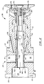
- Fig. 1 is a longitudinal section view, partly broken away and partly in section, of a fuel injection pump incorporating an embodiment of the present invention, showing a poppet valve of the pump in its closed position;
- Fig. 2 is an enlarged, longitudinal section view, partly broken away and partly in section, of a rotor subassembly of the fuel injection pump, showing the poppet valve in its closed position;
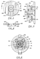
- Fig. 3 is a transverse section view, partly in section, of the rotor subassembly, showing the outer axial end face of a valve stop plate of the rotor subassembly;
- Fig. 4 is a section view, partly in section, of the stop plate, taken substantially along line 4-4 of Fig. 3;
- Fig. 5 is a partial longitudinal section view, partly broken away and partly in section, showing the outer axial end of the rotor subassembly;
- Fig. 6 is a reduced, partial transverse section view, partly broken away and partly in section, of the fuel injection pump, showing a pumping plunger section of the pump;
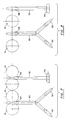
- Fig. 7 is an enlarged layout view, viewed from the axis of the pump rotor, showing the relative orientation of distributor and balancing bores in the rotor and their respective ports and four pumping plunger bores of the pump; and
- Fig. 8 is an enlarged layout view, like Fig. 7, of a modified fuel injection pump having two diametrically opposed pumping plunger bores.
- In the drawings, the same numerals are used to identify the same or like functioning parts or components. Figs. 1 - 7 show an exemplary
fuel injection pump 8 incorporating an embodiment of the present invention. Thepump 8 has anelectrical control valve 9 for regulating the size and timing of each injected charge. Thecontrol valve 9 is a bidirectional flow valve having an axially shiftablepoppet valve member 10, an electromagnet 11 for shifting thepoppet valve 10 to its closed position (shown in Figs. 1 and 2) and acompression spring 180 for shifting thepoppet valve 10 to its open position when the electromagnet 11 is deenergized. Thepump 8 is a Rotary Distributor Type Fuel Injection Pump and may be identical to the pump described in U.S. Patent 5,228,844, dated July 20, 1993, and entitled "Rotary Distributor Type Fuel Injection Pump", except as otherwise disclosed herein. Thus, U.S. Patent 5,228,844, which is incorporated herein by reference, should be referred to for any details of the pump not disclosed herein. - The
exemplary pump 8 is designed for use with a four cylinder engine. Thepump 8 has anelongated pump rotor 12 which is constructed in the form of a single thick sleeve having a stepped, generally cylindrical, outer surface and a steppedcoaxial throughbore 24. Thethroughbore 24 provides a central, coaxial valve bore 32 for thepoppet valve 10. Thepump rotor 12 forms an enlargedpump body 26 at its inner end and a reduced,elongated distributor rotor 28 at its outer end. Thepump body 26 has apumping chamber 30 formed by an annular arrangement of four equiangularly spacedradial bores 16. Apumping plunger 14 is mounted in eachbore 16. Eachbore 16 extends radially inwardly from the outer surface of thepump body 26 to thecentral valve bore 32. The fourplunger bores 16 have the same diameter and have radial axes in the same transverse plane. Thus, thepumping chamber 30 formed by the transverse bank of fourplunger bores 16 is provided by a transverse section of thepump body 26 lying between two transverse planes on opposite sides of and tangential to each of the fourplunger bores 16. The diameter of the fourplunger bores 16 and the diameter of thecentral valve bore 32 are established so that the inner ends ofadjacent plunger bores 16 are adjacent to and preferably tangential to each other as shown in Fig. 7. - The
distributor rotor 28 is rotatably mounted within aninner support sleeve 40 of adistributor head 42. Thedistributor rotor 28 has a very precise rotational fit (e.g., a diametral clearance of 80 - 100 millionths of an inch) within the distributor head bore to ensure adequate sealing and lubrication. Therotor 12 has a relatively short, inclined distributor bore 52 leading to aperipheral distributor port 54. Thedistributor port 54 rotates into registry with four equiangularly spacedoutlet ports 56 in thedistributor head sleeve 40 to distribute the high pressure charges of fuel to fourdistributor outlets 48 in thedistributor head 42 in sequence. If desired, a relatively short,inclined balancing bore 60 is also provided in therotor 12. Thebalancing bore 60 is preferably generally Y-shaped, as shown in Fig. 7, and has a pair ofperipheral balancing ports 62 which are sized and circumferentially spaced from thedistributor port 54 to balance the lateral hydraulic forces on therotor 28. Also, thebalancing ports 62 are circumferentially located to avoid registration with theoutlet ports 56 during the inward pumping strokes of theplungers 14. The distributor bore 52 and the inner or center leg of the Y-shaped balancing bore 60 are drilled from the inner end of thethroughbore 24. - A
pump drive shaft 66 is mounted in coaxial alignment with and adjacent to thepump rotor 12. Thepump rotor 12 is keyed to thedrive shaft 66 by a radially offset, axially extending, drivepin 68. Thedrive pin 68 has a shank (with three equiangularly spaced, axially extending flats) press fit into an axial bore in thedrive shaft 66 and an outer cylindrical head received, without play, within adiametral slot 20 in thepump rotor 12. Thepump rotor 12 is thereby positively coupled to thedrive shaft 66 for rotation by thedrive shaft 66. Thedrive shaft 66 has an enlarged, generally annular, inner end providing a rollershoe support cage 76. Thecage 76 has four equiangularly spacedradial slots 78 aligned with the fourpumping plungers 14. Aroller shoe 80 is slidably mounted in eachslot 78 for engagement with thecorresponding plunger 14. A plunger actuatingroller 82 is supported by eachshoe 80 for engagement with aninternal cam 88 of acam ring 86 surrounding thecage 76. Thecam 88 has four equiangularly spaced cam lobes engageable by the plunger actuatingrollers 82 for periodically calming theplungers 14 inwardly together during rotation of thepump rotor 12. - The
poppet valve 10 has an enlargedannular sealing head 140 at its inner end. The sealinghead 140 has an annular,frustoconical face 142 engageable with an annular,frustoconical valve seat 144 on thepump rotor 12. Fuel is supplied to a coaxial accumulator bore 114 in thedrive shaft 66 via acoaxial bore 112 in thepoppet valve 10. Theaccumulator chamber 114 and a centralcoaxial fuel chamber 115 within the inner end of thepump rotor 12 together provide a fuel supply chamber for supplying fuel to thepumping chamber 30 and receiving fuel spilled from the pumpingchamber 30. During each intake stroke, while thepoppet valve 10 is open, fuel is supplied to thepumping chamber 30 via aperipheral annulus 152 in thepoppet valve 10. During each pumping stroke, after thepoppet valve 10 is reopened, fuel is spilled from the pumpingchamber 30 via theperipheral annulus 152. - The
poppet valve 10 is opened before each outward intake stroke of thepumping plungers 14. During the first part of the intake stroke, fuel is supplied under pressure to thepumping chamber 30 to force theplungers 14 outwardly. Thepoppet valve 10 is timely closed by energizing the valve electromagnet 11. The amount of fuel delivered to thepumping chamber 30 before the poppet valve is closed is determined by the cam profile. The fuel pressure (e.g., 10 psi) in the pump housing cavity opposes the outward movement of theplungers 14 to help prevent plunger overtravel after thepoppet valve 10 is closed. - The
poppet valve 10 remains closed until the end of the following high pressure pumping phase. During that pumping phase, theplungers 14 are actuated inwardly together to deliver a charge of fuel at high pressure from the high pressure chamber formed by the pumpingchamber 30 and the peripheral annulus orchamber 152 in thepoppet valve 10. The electromagnet 11 is normally deenergized before the end of the pumping stroke to open thepoppet valve 10 and spill fuel from the pumpingchamber 30 and thereby terminate the fuel injection event. - A
stator 170 of the electromagnet 11 is mounted on thedistributor head 42 coaxially aligned with thepoppet valve 10. A generally flatcircular armature plate 172 is fixed onto the outer end of thepoppet valve stem 150 by a threaded fastener. Thetransverse armature plate 172 is mounted adjacent to the circular pole face of anE-shaped stator core 174 to be attracted by thestator 170, when energized, to pull thepoppet valve 10 to its closed position against the bias of thecompression spring 180. Anannular shim 176 surrounding thearmature plate 172 is provided between thestator 170 andsleeve 40 to establish a predetermined gap between the flat outer end face of thearmature plate 172 and the opposed flat pole face of thestator 170 when thepoppet valve 10 is in its fully open position. One or more locating pins 177 are employed for positioning theannular shim 176 on the outer axial end face of thesleeve 40. - The
coil compression spring 180 is mounted on thevalve stem 150, at the outer end of thepoppet valve 10, between an inner end washer engaging avalve stem shoulder 182 and anouter end washer 183 engaging a retainingring 184 mounted within an internal annulus in the outer end of thethroughbore 24. Thecompression spring 180 biases the poppet valve 10 (e.g., with a force of 10 pounds) to rapidly open thepoppet valve 10 when thestator 170 is deenergized. - A
valve stop plate 120 is mounted between thearmature plate 172 and the outer axial end face of thedistributor rotor 28. The outer end face of thestop plate 120 is engaged by the inner flat end face of the armature plate to establish the open limit position of thepoppet valve 10. Thestop plate 120 serves as a shim for accurately establishing the open position of thepoppet valve 10. In the alternative, thestop plate 120 is employed in combination with a separate shim (not shown) mounted between thestop plate 120 and the outer axial end face of thedistributor rotor 28. - The
poppet valve 10 andarmature plate 172 are keyed to thedistributor rotor 28 by thestop plate 120. Thestop plate 120 has a generallyrectangular opening 122 that receives aninner hub 173 of thearmature plate 172. Referring to Fig. 3, thestop plate 120 andhub 173 are loosely keyed together by a pair of opposed, parallel side flats on thehub 173 and a pair of parallel flat edges on opposite sides of thestop plate opening 122. Referring to Fig. 5, thestop plate 120 has a pair of outer, axially projecting tabs orflanges 124 with opposed parallel faces that engage diametricallyopposed flats 125 on the outer end of thedistributor rotor 28. Thepoppet valve 10,armature plate 172 and stopplate 120 are thereby positively coupled to therotor 12 for rotation by therotor 12. - In the prior art design shown in U.S. Patent 5,228,844, the
poppet valve 10 can bounce off the valve stop when thepoppet valve 10 is opened by its actuating spring, sometimes causing thepoppet valve 10 to momentarily reseat. In the present invention, thevalve stop 120 serves as a hydraulic damper plate as thearmature plate 172 approaches engagement with thevalve stop plate 120. For that purpose, the outer face of thevalve stop 120 has a plurality ofparallel grooves 129 andintermediate lands 128. Thegrooves 129 and lands 128 are sized to dampen or cushion thepoppet valve 10 during the last 0.001 to 0.0015 inch of opening movement of thevalve 10 before thearmature plate 172 engages thestop plate 120. In the shown embodiment, except for the twooutermost lands 128, each of the lands 128 (and each of the intermediate grooves 129) has a width of 0.062 inch (or approximately one-sixteenth inch). Also, thearmature plate 172 has a number of vent holes 175. The vent holes 175 andgrooves 129 in thestop plate 120 facilitate fuel flow into and out of the gap between theplates 172, 210 to facilitate engagement and separation of thevalve stop 120 andarmature 172. - A
thrust washer 22 and thrustbearing 34 are interposed between an axially outwardly facingend shoulder 27 of thepump body 26 and the opposed inner axial end face of thedistributor head sleeve 40. Prior thrust bearings like that shown in U.S. Patent 5,228,844 used fuel as a lubricant to support the axial force on therotor 12 produced by the system pressure at the inner end of therotor 12. In such prior art designs the thrust bearing load was not adequately supported by the fuel lubricant and such that surface galling of the opposed bearing faces occurred. In the subject design, the needle thrust bearing 34 carries the thrust load produced by the system pressure to prevent such mechanical failures. Thethrust washer 22 may be keyed to thepump rotor 12, if desired. - The periodic compression of fuel in the
pumping chamber 30,valve annulus 152, distributor bore 52 and balancing bore 60 generates a great amount of heat. The rate of heat generation is dependent on the pump speed, pumping pressure and pumping stroke. The pumping chamber section of therotor 12 generates the greatest amount of heat. A rapid change in the rate of heat generation can cause temperature gradients in thepump rotor 12 anddistributor head 42. The temperature gradients are the greatest within thepump body 26 and within the adjacent inner axial end of thedistributor rotor 28 andsleeve 40. Thus, the most critical section of the precise rotational fit of thedistributor rotor 28 within thesleeve 40 is the section closest to thepump body 26. When thedistributor rotor 28 is hotter thansleeve 40, the diametral clearance between those parts can be reduced sufficiently to prevent effective lubrication and cause rotor seizure. The temperature of thedistributor rotor 28 andsleeve 40 can vary because of their different masses and the different rates of thermal conductivity within those parts. - In accordance with the present invention, an
isolation annulus 46 is provided in the inner axial end face of thesleeve 40 to thermally isolate, in part, an innercantilever end section 45 of the sleeve from the rest of thesleeve 40 and thereby improve the thermal coupling between thecantilever end section 45 and the corresponding section of therotor 12. This allows thecantilever end section 45 to react to thermal transients at approximately the same rate as the corresponding section of thedistributor rotor 28, thereby minimizing or eliminating the difference in temperature and thermal expansion of thepump rotor 12 andcantilever end section 45. In the shown embodiment, the axial length of theisolation annulus 46 is approximately one-eighth inch and is limited by the need to maintain the structural rigidity of thesleeve 40 around each of the outlet bores 48 through thesleeve 40. Unbroken sealing surfaces are provided along the full length of thecantilever end section 45 and the corresponding section of thedistributor rotor 28. Also, thecantilever end section 45 provides over one-half the axial length of the sealing section between thedistributor port 56 and the inner axial end of the seal. The radial height of the annulus is approximately one-sixteenth inch. The radial thickness of thecantilever end section 45 is approximately 0.085 inch and is established to provide the desired thermal coupling of thecantilever end section 45 with thedistributor rotor 28 during cold starting and pump acceleration and at the same time maintain an acceptable seal between thecantilever end section 45 and thedistributor rotor 28. - In previous designs, the
inlet port 58 of the distributor bore 52 and theinlet port 64 of the balancing bore 60 were axially spaced from the bank of plunger bores 16 or angularly aligned with and connected directly to the plunger bores 16. In such designs, the hoop stress within thedistributor rotor 28 surrounding eachinlet port rotor 28 could be overstressed around theinlet ports distributor rotor 28. In accordance with the present invention, thebores inlet ports inlet ports inlet ports inlet ports peripheral annulus 152 in thepoppet valve 10. In the optimum arrangement shown, theinlet ports valve seat 144 might adversely affect the structural rigidity of thevalve seat 144. Any such intrusion in the opposite direction reduces the axial length of the seal between therotor 12 and thepoppet valve 10. The axial length of that seal is limited by the provision of aperipheral bleed annulus 145 and bleed hole in thevalve stem 150 which bleeds leakage fuel into the internalcoaxial bore 112 within thepoppet valve 10. Thebleed annulus 145 is axially located inwardly of the inner axial end of thedistributor rotor 28 to minimize the internal pressure within thedistributor rotor 28 and thus any enlargement of thedistributor rotor 28 by that internal pressure. - In a modified embodiment, the pumping
chamber 30 is formed by an annular arrangement of two diametrally opposed plunger bores 16 instead of the described four plunger bores 16. In that event, the distributor bore 52 and balancing bore 60 are preferably angularly offset 90° from the axes of the plunger bores 16 as shown in Fig. 8. Theinlet ports peripheral annulus 152 in thepoppet valve 10. Also, theinlet ports - As will be apparent to persons skilled in the art, various modifications, adaptations and variations of the foregoing specific disclosure can be made without departing from the teachings of the present invention.
Claims (24)
- A fuel injection pump having a pump rotor providing a pump body and distributor rotor in coaxial alignment, the pump body having a pumping chamber with an annular arrangement of pumping plunger bores with axes extending generally radially outwardly from the axis of the pump rotor; a pumping plunger mounted in each plunger bore; a cam surrounding the pump body for reciprocating the pumping plungers for supplying intake charges of fuel to the pumping chamber and delivering high pressure charges of fuel from the pumping chamber for fuel injection; a drive shaft in coaxial alignment with the pump rotor adjacent to the pump rotor; a distributor head, with an inner rotor support sleeve, having a plurality of distributor outlets; the distributor rotor being rotatably mounted within the rotor support sleeve for distributing high pressure charges of fuel to the distributor outlets; the pump rotor having a central coaxial throughbore providing a valve bore intersecting the plunger bores and an annular valve seat at one end of the valve bore; an elongated valve member, mounted in the valve bore, having a sealing head at one end thereof engageable with the annular valve seat and extending from the sealing head toward the other end of the valve bore, the valve member being axially shiftable in the valve bore between a closed position thereof with the sealing head in engagement with the valve seat and an open position thereof with the sealing head axially spaced from the valve seat; an electromagnet at the opposite end of the valve member from the sealing head and axially outwardly from the pump rotor, the electromagnet comprising a transverse armature plate fixed to said opposite end of the valve member and a stator, axially outwardly from said armature plate, operable when energized to attract the armature plate to pull the valve member in one axial direction toward the stator to its closed position; spring means shifting the valve member in the opposite axial direction to its open position when the electromagnet is deenergized; first coupling means coupling the adjacent inner ends of the drive shaft and pump rotor for positive rotation of the pump rotor with the drive shaft; a valve stop mounted on the pump rotor between the pump rotor and the armature plate, the valve stop and armature plate having opposed transverse faces engageable for establishing said open position of the valve member, one of said transverse faces having a plurality of lands engageable by the other transverse face and a plurality of intermediate grooves, the lands and grooves cooperating to produce a hydraulic damping effect on the armature plate as the valve member is axially shifted to its said open position by the spring means, the valve stop comprising second and third coupling means respectively coupling the valve stop to the pump rotor and the armature plate to the valve stop for positive rotation of the armature plate and valve stop with the pump rotor.
- A fuel injection pump according to claim 1 wherein said lands and grooves cooperate to dampen the armature plate during approximately the last 0.001 inch of armature plate travel before engagement of said opposed transverse faces of the armature plate and the valve stop.
- A fuel injection pump according to claim 1 wherein the armature plate comprises a plurality of vent holes for venting the gap between said opposed transverse faces of the armature plate and the valve stop.
- A fuel injection pump according to claim 1 wherein said first coupling means comprises a radial slot in the pump rotor and a radially offset and axially extending pin having a shank press fit into an opening in the drive shaft and a circular head received within the radial slot in the rotor.
- A fuel injection pump according to claim 1 wherein the armature plate has a hub and the valve stop has a central opening receiving the hub and wherein the valve stop and hub have cooperating surfaces providing said third coupling means.
- A fuel injection pump according to claim 5 wherein said second coupling means comprises a plurality of axially inwardly projecting flanges on the valve stop having opposed surfaces engaging cooperating surfaces on the pump rotor to key the valve stop to the pump rotor.
- A fuel injection pump according to claim 1 further comprising a thrust bearing between the pump body and the rotor support sleeve, the thrust bearing comprising a thrust washer engaging the pump body and a needle bearing between the thrust washer and the rotor support sleeve to transmit the axial load on the pump rotor from the pump body through the thrust washer and needle bearing to the rotor support sleeve.
- A fuel injection pump according to claim 1 wherein the rotor support sleeve has a coaxial isolation annulus at the axial end thereof toward the pump body forming an annular cantilever end section of the sleeve in sealing engagement with a corresponding section of the distributor rotor.
- In a fuel injection pump having a pump rotor providing a pump body and distributor rotor in coaxial alignment, the pump body having a pumping chamber with an annular arrangement of a plurality of pumping plunger bores with respective axes angularly spaced about and extending generally radially outwardly from the axis of the pump rotor; a pumping plunger mounted in each plunger bore; a cam surrounding the pump body for reciprocating the pumping plungers for alternately supplying intake charges of fuel to the pumping chamber and delivering high pressure charges of fuel from the pumping chamber for fuel injection; the pump rotor having a coaxial bore providing a coaxial valve bore intersecting the plunger bores; a valve member mounted in the valve bore between the plurality of plunger bores and axially shiftable in the valve bore between open and closed axial positions thereof, the valve member forming a peripheral chamber which communicates with the plunger bores and which forms with the pumping chamber a high pressure chamber in the closed position of the valve member; means for actuating the valve member to its open and closed positions; and a distributor head with a rotor support bore and a plurality of distributor outlets; the distributor rotor being rotatably mounted in the rotor support bore and having at least one peripheral distributor port for distributing the high pressure charges of fuel from the high pressure chamber to the distributor outlets; the pump rotor having a distributor bore connecting the high pressure chamber to the distributor port, the improvement wherein the distributor bore has an axially extending and radially inclined inlet end section with an inlet port which opens into the high pressure chamber between the angularly spaced axes of one pair of adjacent plunger bores, at least largely within a transverse section of the pump body between transverse planes on opposite sides of and tangential to said annular arrangement of plunger bores.
- A fuel injection pump according to claim 9 wherein said annular arrangement of plunger bores comprises at least four pumping plunger bores, wherein the plunger bores have angularly spaced axes in the same transverse plane, wherein the inner ends of the plunger bores of said one pair of adjacent plunger bores are contiguous to each other and wherein the inlet port of the inlet end section of the distributor bore opens into each of the plunger bores of said one pair of adjacent plunger bores.
- A fuel injection pump according to claim 9 wherein said annular arrangement of plunger bores consists of two diametrally opposed pumping plunger bores and wherein the inlet port of the inlet end section of the distributor bore opens into the peripheral chamber in the valve member between said two diametrally opposed plunger bores.
- A fuel injection pump according to claim 11 wherein the inlet port of the inlet end section of the distributor bore opens into the peripheral chamber in the valve member at a point approximately equidistant from the axes of said two diametrically opposed plunger bores.
- A fuel injection pump according to claim 9 wherein the distributor rotor has at least one peripheral balancing port and a balancing bore connecting the high pressure chamber to the balancing port, the balancing bore having an axially extending and radially inclined inlet end section with an inlet port angularly spaced from the inlet port of the distributor bore and opening into the high pressure chamber between the angularly spaced axes of a second pair of adjacent plunger bores, at least largely within said transverse section of the pump body.
- In a fuel injection pump having a pump rotor providing a pump body and distributor rotor in coaxial alignment, the pump body having a pumping chamber with an annular arrangement of a plurality of pumping plunger bores with axes extending generally radially outwardly from the axis of the pump rotor; a pumping plunger mounted in each plunger bore; a cam surrounding the pump body for reciprocating the pumping plungers for supplying intake charges of fuel to the pumping chamber and delivering high pressure charges of fuel from the pumping chamber for fuel injection; and a distributor head with a rotor support bore and a plurality of distributor outlets; the distributor rotor being rotatably mounted in the rotor support bore and having at least one peripheral distributor port for distributing the high pressure charges of fuel to the distributor outlets; the improvement wherein the distributor head comprises a cantilevered annular end section, at the axial end of the distributor head toward the pump body, having a distributor head bore section which provides a sealing section receiving a corresponding section of the distributor rotor, said sealing section and corresponding section of the distributor rotor having unbroken peripheral sealing surfaces in sealing association along substantially the full length of said sealing section, said cantilevered end section having a radial thickness substantially less than the radial thickness of the rest of the distributor head to reduce the rate of thermal conductivity from said cantilevered end section and thereby to increase the rate of thermal expansion of said sealing section to conform to said corresponding distributor rotor section.
- A fuel injection pump according to claim 14 wherein said sealing section has an axial length of at least about one-eighth inch and a radial thickness of about 0.085 inch.
- A fuel injection pump according to claim 14 wherein said cantilevered end section is formed by an annulus within the axial end of the distributor head toward the pump body.
- A fuel injection pump according to claim 14 wherein the distributor head has an inner sleeve having said distributor head bore and said cantilevered annular end section.
- A fuel injection pump having a pump rotor providing a pump body and distributor rotor in coaxial alignment, the pump body having a pumping chamber with an annular arrangement of pumping plunger bores with axes extending generally radially outwardly from the axis of the pump rotor; a pumping plunger mounted in each plunger bore; a cam surrounding the pump body for reciprocating the pumping plungers for supplying intake charges of fuel to the pumping chamber and delivering high pressure charges of fuel from the pumping chamber for fuel injection; a drive shaft in coaxial alignment with the pump rotor adjacent to the pump rotor; a distributor head with a rotor support bore and a plurality of distributor outlets; the distributor rotor being rotatably mounted within the rotor support bore for distributing high pressure charges of fuel to the distributor outlets; the pump rotor having a central coaxial throughbore providing a valve bore intersecting the plunger bores and an annular valve seat at one end of the valve bore; an elongated valve member, mounted in the valve bore, having a sealing head at one end thereof engageable with the annular valve seat and extending in one axial direction from the sealing head toward the other end of the valve bore, the valve member being axially shiftable in the valve bore in said one axial direction to a closed position thereof with the sealing head in engagement with the valve seat and in the opposite axial direction to an open position thereof with the sealing head axially spaced from the valve seat; an electromagnet at the opposite end of the valve member from the sealing head, the electromagnet comprising a transverse armature plate fixed to said opposite end of the valve member and a stator, axially spaced in said one axial direction from said armature plate, operable when energized to attract the armature plate to pull the valve member in said one axial direction toward the stator to its closed position; spring means shifting the valve member in the opposite axial direction to its open position when the electromagnet is deenergized; a transverse end plate mounted on the outer end of the pump rotor between the pump rotor and the armature plate, the armature plate and the end plate having opposed transverse surfaces in face to face engagement in said open position of the valve member, at least one of said opposed transverse surfaces having a plurality of lands engageable by the other transverse surface and intermediate grooves between said lands to conduct fuel from between the opposed transverse surfaces as the valve member is shifted by the spring means to its said open position.
- A fuel injection pump according to claim 18 wherein the transverse end plate has said one transverse surface with said lands and grooves.
- A fuel injection pump according to claim 9 wherein the inlet port of the inlet end section of the distributor bore opens into the peripheral chamber in the valve member at a point approximately equidistant from the axes of said one pair of adjacent plunger bores.
- In a fuel injection pump having a pump rotor providing a pump body and distributor rotor in coaxial alignment, the pump body having a pumping chamber with an annular arrangement of a plurality of pumping plunger bores with axes extending generally radially outwardly from the axis of the pump rotor; a pumping plunger mounted in each plunger bore; a cam surrounding the pump body for reciprocating the pumping plungers for supplying intake charges of fuel to the pumping chamber and delivering high pressure charges of fuel from the pumping chamber for fuel injection; and a distributor head with a rotor support bore and a plurality of distributor outlets; the distributor rotor being rotatably mounted in the rotor support bore and having at least one peripheral distributor port for distributing the high pressure charges of fuel to the distributor outlets; the improvement wherein the pump comprises an annular thrust bearing between the pump body and distributor head comprising a thrust washer engaging the pump body and a needle bearing between the thrust washer and the distributor head to transmit the axial load on the pump rotor from the pump body through the thrust washer and needle bearing to the distributor head.
- A fuel injection pump according to claim 21 wherein the distributor head comprises an inner rotor support sleeve having said rotor support bore, and wherein the thrust bearing is provided between the pump body and the rotor support sleeve.
- A fuel injection pump having a pump rotor providing a pump body and distributor rotor in coaxial alignment, the pump body having a pumping chamber with an annular arrangement of pumping plunger bores with axes extending generally radially outwardly from the axis of the pump rotor; a pumping plunger mounted in each plunger bore; an annular cam surrounding the pump body for reciprocating the pumping plungers for supplying intake charges of fuel to the pumping chamber and delivering high pressure charges of fuel from the pumping chamber for fuel injection; a drive shaft in coaxial alignment with the pump rotor adjacent to the pump rotor, the drive shaft having an enlarged inner annular end surrounding the pump body and having an annular arrangement of radial slots in radial alignment with the pumping plunger bores respectively, a roller shoe mounted in each slot for engagement with the respective pumping plunger, a roller mounted on each roller shoe for engagement with the annular cam for reciprocating the pumping plungers; a distributor head with a rotor support bore and a plurality of distributor outlets; the distributor rotor being rotatably mounted within the rotor support bore for distributing high pressure charges of fuel to the distributor outlets; the pump rotor having a central coaxial throughbore providing a valve bore intersecting the plunger bores and an annular valve seat at one end of the valve bore; an elongated valve member, mounted in the valve bore, having a sealing head at one end thereof engageable with the annular valve seat and extending from the sealing head toward the other end of the valve bore, the valve member being axially shiftable in the valve bore between a closed position thereof with the sealing head in engagement with the valve seat and an open position thereof with the sealing head axially spaced from the valve seat; an electromagnet at the opposite end of the valve member from the sealing head, operable when energized to actuate the valve member in one axial direction to one of its positions; spring means shifting the valve member in the opposite axial direction.to its other position when the electromagnet is deenergized; the pump rotor and drive shaft having opposed inner end faces with a radial slot in the inner end face of the pump rotor and a radially offset and axially extending opening in the inner end face of the drive shaft, and a pin having a shank press fit into said opening in the inner end face of the drive shaft and a circular head received with the radial slot in the rotor for coupling the pump rotor to the drive shaft.
- A fuel injection pump having a pump rotor providing a pump body and distributor rotor in coaxial alignment, the pump body having a pumping chamber with an annular arrangement of pumping plunger bores with axes extending generally radially outwardly from the axis of the pump rotor; a pumping plunger mounted in each plunger bore; a cam surrounding the pump body for reciprocating the pumping plungers for supplying intake charges of fuel to the pumping chamber and delivering high pressure charges of fuel from the pumping chamber for fuel injection; a drive shaft in coaxial alignment with the pump rotor adjacent to the pump rotor; a distributor head having a plurality of distributor outlets; the distributor rotor being rotatably mounted within the distributor head for distributing high pressure charges of fuel to the distributor outlets; the pump rotor having a central coaxial throughbore providing a valve bore intersecting the plunger bores and an annular valve seat at one end of the valve bore; an elongated valve member, mounted in the valve bore, having a sealing head at one end thereof engageable with the annular valve seat and extending from the sealing head toward the other end of the valve bore, the valve member being axially shiftable in the valve bore between a closed position thereof with the sealing head in engagement with the valve seat and an open position thereof with the sealing head axially spaced from the valve seat; an electromagnet at the opposite end of the valve member from the sealing head, the electromagnet comprising an armature fixed to said opposite end of the valve member and a stator axially spaced from the valve member and operable when energized to attract the armature to pull the valve member in one axial direction toward the stator to one of its said positions; spring means shifting the valve member in the opposite axial direction to its other position when the electromagnet is deenergized; a valve stop mounted on the end of the pump rotor between the pump rotor and the armature and engageable by the armature to establish said other position of the valve member when the electromagnet is deenergized; the armature having an inner hub and the valve stop having a central opening receiving the inner hub, the valve stop and inner hub having cooperating surfaces keying the armature to the valve stop, and the valve stop and pump rotor having cooperating means keying the valve stop to the pump rotor.
Applications Claiming Priority (2)
| Application Number | Priority Date | Filing Date | Title |
|---|---|---|---|
| US08/152,320 US5540564A (en) | 1993-11-12 | 1993-11-12 | Rotary distributor type fuel injection pump |
| US152320 | 1993-11-12 |
Publications (2)
| Publication Number | Publication Date |
|---|---|
| EP0657641A2 true EP0657641A2 (en) | 1995-06-14 |
| EP0657641A3 EP0657641A3 (en) | 1995-09-13 |
Family
ID=22542425
Family Applications (1)
| Application Number | Title | Priority Date | Filing Date |
|---|---|---|---|
| EP94630046A Withdrawn EP0657641A3 (en) | 1993-11-12 | 1994-08-25 | Rotary distributor type fuel injection pump. |
Country Status (7)
| Country | Link |
|---|---|
| US (1) | US5540564A (en) |
| EP (1) | EP0657641A3 (en) |
| JP (1) | JPH07166999A (en) |
| KR (1) | KR100318688B1 (en) |
| BR (1) | BR9402976A (en) |
| CZ (1) | CZ286780B6 (en) |
| PL (1) | PL174827B1 (en) |
Cited By (12)
| Publication number | Priority date | Publication date | Assignee | Title |
|---|---|---|---|---|
| EP0812388A1 (en) * | 1995-02-21 | 1997-12-17 | Diesel Technology Company | Fuel pumping and injection systems |
| EP1557559A1 (en) * | 2002-10-29 | 2005-07-27 | Bosch Automotive Systems Corporation | High flow rate fuel valve and fuel supply pump with the valve |
| US7494130B2 (en) | 2006-02-13 | 2009-02-24 | Freudenberg-Nok General Partnership | Bi-directional pattern for dynamic seals |
| US7775528B2 (en) | 2006-02-13 | 2010-08-17 | Freudenberg-Nok General Partnership | Bi-directional pattern for dynamic seals |
| US7891670B2 (en) | 2008-02-01 | 2011-02-22 | Freudenberg-Nok General Partnership | Multi-directional shaft seal |
| US8376369B2 (en) | 2006-02-10 | 2013-02-19 | Freudenberg-Nok General Partnership | Seal with spiral grooves and contamination entrapment dams |
| US8454025B2 (en) | 2010-02-24 | 2013-06-04 | Freudenberg-Nok General Partnership | Seal with spiral grooves and mid-lip band |
| US8919782B2 (en) | 2012-10-19 | 2014-12-30 | Freudenberg-Nok General Partnership | Dynamic lay down lip seal with bidirectional pumping feature |
| US8925927B2 (en) | 2006-02-10 | 2015-01-06 | Freudenberg-Nok General Partnership | Seal with controllable pump rate |
| CN109737054A (en) * | 2019-01-21 | 2019-05-10 | 唐山德厚机械制造有限公司 | A kind of electro-hydraulic pump of rotary cylinder-block seben combination |
| PL423777A1 (en) * | 2017-12-07 | 2019-06-17 | Pogoda Mirosław Zakład Produkcyjno-Usługowy | Rotary fuel pump head |
| GB2607613A (en) * | 2021-06-09 | 2022-12-14 | Delphi Tech Ip Ltd | Valve assembly for a fuel pump |
Families Citing this family (15)
| Publication number | Priority date | Publication date | Assignee | Title |
|---|---|---|---|---|
| DE19650865A1 (en) * | 1996-12-07 | 1998-06-10 | Bosch Gmbh Robert | magnetic valve |
| DE19923422C2 (en) * | 1999-05-21 | 2003-05-08 | Bosch Gmbh Robert | Electronic injection system |
| JP3525883B2 (en) * | 1999-12-28 | 2004-05-10 | 株式会社デンソー | Fuel injection pump |
| US8034026B2 (en) | 2001-05-18 | 2011-10-11 | Deka Products Limited Partnership | Infusion pump assembly |
| MXPA03010576A (en) | 2001-05-18 | 2004-05-27 | Deka Products Lp | Infusion set for a fluid pump. |
| US7610902B2 (en) * | 2007-09-07 | 2009-11-03 | Gm Global Technology Operations, Inc. | Low noise fuel injection pump |
| US7509948B1 (en) | 2007-10-01 | 2009-03-31 | Caterpillar Inc. | Variable displacement pump with an anti-stiction device |
| US8708376B2 (en) | 2008-10-10 | 2014-04-29 | Deka Products Limited Partnership | Medium connector |
| US8016789B2 (en) | 2008-10-10 | 2011-09-13 | Deka Products Limited Partnership | Pump assembly with a removable cover assembly |
| US8267892B2 (en) | 2008-10-10 | 2012-09-18 | Deka Products Limited Partnership | Multi-language / multi-processor infusion pump assembly |
| US8262616B2 (en) | 2008-10-10 | 2012-09-11 | Deka Products Limited Partnership | Infusion pump assembly |
| US8223028B2 (en) | 2008-10-10 | 2012-07-17 | Deka Products Limited Partnership | Occlusion detection system and method |
| US9180245B2 (en) | 2008-10-10 | 2015-11-10 | Deka Products Limited Partnership | System and method for administering an infusible fluid |
| US8066672B2 (en) | 2008-10-10 | 2011-11-29 | Deka Products Limited Partnership | Infusion pump assembly with a backup power supply |
| US8316826B2 (en) * | 2009-01-15 | 2012-11-27 | Caterpillar Inc. | Reducing variations in close coupled post injections in a fuel injector and fuel system using same |
Citations (4)
| Publication number | Priority date | Publication date | Assignee | Title |
|---|---|---|---|---|
| GB2135758A (en) * | 1983-02-26 | 1984-09-05 | Lucas Ind Plc | Fluid control valve |
| EP0321135A1 (en) * | 1987-12-12 | 1989-06-21 | Lucas Industries Public Limited Company | Control valve |
| US5143291A (en) * | 1992-03-16 | 1992-09-01 | Navistar International Transportation Corp. | Two-stage hydraulic electrically-controlled unit injector |
| US5228844A (en) * | 1992-10-14 | 1993-07-20 | Stanadyne Automotive Corp. | Rotary distributor type fuel injection pump |
Family Cites Families (5)
| Publication number | Priority date | Publication date | Assignee | Title |
|---|---|---|---|---|
| GB8725176D0 (en) * | 1987-10-27 | 1987-12-02 | Lucas Ind Plc | Gasolene injector |
| US4941447A (en) * | 1989-02-21 | 1990-07-17 | Colt Industries Inc. | Metering valve |
| US5054691A (en) * | 1989-11-03 | 1991-10-08 | Industrial Technology Research Institute | Fuel oil injector with a floating ball as its valve unit |
| US5103792A (en) * | 1990-10-16 | 1992-04-14 | Stanadyne Automotive Corp. | Processor based fuel injection control system |
| US5215449A (en) * | 1991-12-05 | 1993-06-01 | Stanadyne Automotive Corp. | Distributor type fuel injection pump |
-
1993
- 1993-11-12 US US08/152,320 patent/US5540564A/en not_active Expired - Fee Related
-
1994
- 1994-06-29 JP JP6170064A patent/JPH07166999A/en active Pending
- 1994-07-12 KR KR1019940016738A patent/KR100318688B1/en not_active IP Right Cessation
- 1994-07-28 BR BR9402976A patent/BR9402976A/en not_active Application Discontinuation
- 1994-08-25 EP EP94630046A patent/EP0657641A3/en not_active Withdrawn
- 1994-08-29 PL PL94304823A patent/PL174827B1/en unknown
- 1994-08-30 CZ CZ19942090A patent/CZ286780B6/en not_active IP Right Cessation
Patent Citations (4)
| Publication number | Priority date | Publication date | Assignee | Title |
|---|---|---|---|---|
| GB2135758A (en) * | 1983-02-26 | 1984-09-05 | Lucas Ind Plc | Fluid control valve |
| EP0321135A1 (en) * | 1987-12-12 | 1989-06-21 | Lucas Industries Public Limited Company | Control valve |
| US5143291A (en) * | 1992-03-16 | 1992-09-01 | Navistar International Transportation Corp. | Two-stage hydraulic electrically-controlled unit injector |
| US5228844A (en) * | 1992-10-14 | 1993-07-20 | Stanadyne Automotive Corp. | Rotary distributor type fuel injection pump |
Cited By (15)
| Publication number | Priority date | Publication date | Assignee | Title |
|---|---|---|---|---|
| EP0812388A4 (en) * | 1995-02-21 | 1999-07-21 | Diesel Tech Co | Fuel pumping and injection systems |
| EP0812388A1 (en) * | 1995-02-21 | 1997-12-17 | Diesel Technology Company | Fuel pumping and injection systems |
| EP1557559A1 (en) * | 2002-10-29 | 2005-07-27 | Bosch Automotive Systems Corporation | High flow rate fuel valve and fuel supply pump with the valve |
| EP1557559A4 (en) * | 2002-10-29 | 2006-06-07 | Bosch Automotive Systems Corp | High flow rate fuel valve and fuel supply pump with the valve |
| US8925927B2 (en) | 2006-02-10 | 2015-01-06 | Freudenberg-Nok General Partnership | Seal with controllable pump rate |
| US8376369B2 (en) | 2006-02-10 | 2013-02-19 | Freudenberg-Nok General Partnership | Seal with spiral grooves and contamination entrapment dams |
| US7494130B2 (en) | 2006-02-13 | 2009-02-24 | Freudenberg-Nok General Partnership | Bi-directional pattern for dynamic seals |
| US7775528B2 (en) | 2006-02-13 | 2010-08-17 | Freudenberg-Nok General Partnership | Bi-directional pattern for dynamic seals |
| US7891670B2 (en) | 2008-02-01 | 2011-02-22 | Freudenberg-Nok General Partnership | Multi-directional shaft seal |
| US8454025B2 (en) | 2010-02-24 | 2013-06-04 | Freudenberg-Nok General Partnership | Seal with spiral grooves and mid-lip band |
| US8919782B2 (en) | 2012-10-19 | 2014-12-30 | Freudenberg-Nok General Partnership | Dynamic lay down lip seal with bidirectional pumping feature |
| PL423777A1 (en) * | 2017-12-07 | 2019-06-17 | Pogoda Mirosław Zakład Produkcyjno-Usługowy | Rotary fuel pump head |
| CN109737054A (en) * | 2019-01-21 | 2019-05-10 | 唐山德厚机械制造有限公司 | A kind of electro-hydraulic pump of rotary cylinder-block seben combination |
| GB2607613A (en) * | 2021-06-09 | 2022-12-14 | Delphi Tech Ip Ltd | Valve assembly for a fuel pump |
| GB2607613B (en) * | 2021-06-09 | 2023-10-18 | Delphi Tech Ip Ltd | Valve assembly for a fuel pump |
Also Published As
| Publication number | Publication date |
|---|---|
| BR9402976A (en) | 1996-06-18 |
| KR950014546A (en) | 1995-06-16 |
| PL304823A1 (en) | 1995-05-15 |
| CZ209094A3 (en) | 1995-05-17 |
| US5540564A (en) | 1996-07-30 |
| KR100318688B1 (en) | 2002-03-21 |
| EP0657641A3 (en) | 1995-09-13 |
| JPH07166999A (en) | 1995-06-27 |
| CZ286780B6 (en) | 2000-07-12 |
| PL174827B1 (en) | 1998-09-30 |
Similar Documents
| Publication | Publication Date | Title |
|---|---|---|
| US5540564A (en) | Rotary distributor type fuel injection pump | |
| US5215449A (en) | Distributor type fuel injection pump | |
| US5228844A (en) | Rotary distributor type fuel injection pump | |
| US5888054A (en) | Fuel pump having dual profile cam ring for driving low and high pressure reciprocating plungers | |
| SU1083924A3 (en) | Pumping device | |
| US5775203A (en) | High pressure fuel pump assembly | |
| EP0524132B1 (en) | Fuel system for rotary distributor fuel injection pump | |
| EP0921300B1 (en) | Advance arrangement for a fuel pump | |
| US4552117A (en) | Fuel injection pump with spill control mechanism | |
| US2436797A (en) | Fuel injection pump | |
| US5980214A (en) | Fluid pump with split plungers | |
| US4667641A (en) | Injection pump with radially mounted spill control valve | |
| US5685275A (en) | Fuel injection pump with spill and line pressure regulating systems | |
| JPH08226359A (en) | Fuel pumping device | |
| US10975816B2 (en) | Roller drive mechanism for GDI pump | |
| EP0372713B1 (en) | Fuel injection pump | |
| JPS61234264A (en) | Liquid fuel pump device | |
| EP0939222A2 (en) | Fuel pump | |
| US2666391A (en) | Fuel injection pump | |
| JPS62261663A (en) | Inner cam system distribution type fuel-injection pump | |
| Jones et al. | Rotary selector valve | |
| JPH04276173A (en) | Injection timing adjuster for distribution type fuel injection pump | |
| GB2299689A (en) | Hydraulic governor for a fuel pump |
Legal Events
| Date | Code | Title | Description |
|---|---|---|---|
| PUAI | Public reference made under article 153(3) epc to a published international application that has entered the european phase |
Free format text: ORIGINAL CODE: 0009012 |
|
| AK | Designated contracting states |
Kind code of ref document: A2 Designated state(s): DE FR GB IT |
|
| PUAL | Search report despatched |
Free format text: ORIGINAL CODE: 0009013 |
|
| AK | Designated contracting states |
Kind code of ref document: A3 Designated state(s): DE FR GB IT |
|
| STAA | Information on the status of an ep patent application or granted ep patent |
Free format text: STATUS: THE APPLICATION IS DEEMED TO BE WITHDRAWN |
|
| 18D | Application deemed to be withdrawn |
Effective date: 19960314 |