EP0657640A1 - Automotive fuel pump with helical impeller - Google Patents
Automotive fuel pump with helical impeller Download PDFInfo
- Publication number
- EP0657640A1 EP0657640A1 EP94307695A EP94307695A EP0657640A1 EP 0657640 A1 EP0657640 A1 EP 0657640A1 EP 94307695 A EP94307695 A EP 94307695A EP 94307695 A EP94307695 A EP 94307695A EP 0657640 A1 EP0657640 A1 EP 0657640A1
- Authority
- EP
- European Patent Office
- Prior art keywords
- blade
- fuel
- inlet
- pumping
- impeller
- Prior art date
- Legal status (The legal status is an assumption and is not a legal conclusion. Google has not performed a legal analysis and makes no representation as to the accuracy of the status listed.)
- Granted
Links
- 239000000446 fuel Substances 0.000 title claims abstract description 74
- 238000005086 pumping Methods 0.000 claims abstract description 77
- 239000002828 fuel tank Substances 0.000 claims abstract description 7
- 239000012530 fluid Substances 0.000 claims description 3
- 238000004891 communication Methods 0.000 claims description 2
- 230000001172 regenerating effect Effects 0.000 abstract description 6
- 230000003247 decreasing effect Effects 0.000 abstract description 3
- 230000007246 mechanism Effects 0.000 description 5
- XAGFODPZIPBFFR-UHFFFAOYSA-N aluminium Chemical compound [Al] XAGFODPZIPBFFR-UHFFFAOYSA-N 0.000 description 3
- 229910052782 aluminium Inorganic materials 0.000 description 3
- 239000004411 aluminium Substances 0.000 description 3
- 239000011213 glass-filled polymer Substances 0.000 description 3
- 238000004519 manufacturing process Methods 0.000 description 3
- 229920000642 polymer Polymers 0.000 description 3
- 239000002131 composite material Substances 0.000 description 2
- 230000009977 dual effect Effects 0.000 description 2
- 238000002347 injection Methods 0.000 description 2
- 239000007924 injection Substances 0.000 description 2
- 238000000034 method Methods 0.000 description 2
- 239000004033 plastic Substances 0.000 description 2
- 238000010926 purge Methods 0.000 description 2
- 229920001897 terpolymer Polymers 0.000 description 2
- 229920001169 thermoplastic Polymers 0.000 description 2
- 239000004416 thermosoftening plastic Substances 0.000 description 2
- LFQSCWFLJHTTHZ-UHFFFAOYSA-N Ethanol Chemical compound CCO LFQSCWFLJHTTHZ-UHFFFAOYSA-N 0.000 description 1
- 241000566107 Scolopax Species 0.000 description 1
- 241000863032 Trieres Species 0.000 description 1
- 238000010276 construction Methods 0.000 description 1
- 239000002283 diesel fuel Substances 0.000 description 1
- 238000006073 displacement reaction Methods 0.000 description 1
- 239000013013 elastic material Substances 0.000 description 1
- 239000003502 gasoline Substances 0.000 description 1
- 239000000463 material Substances 0.000 description 1
- 230000002093 peripheral effect Effects 0.000 description 1
- 230000010349 pulsation Effects 0.000 description 1
- 239000012815 thermoplastic material Substances 0.000 description 1
Images


Classifications
-
- F—MECHANICAL ENGINEERING; LIGHTING; HEATING; WEAPONS; BLASTING
- F02—COMBUSTION ENGINES; HOT-GAS OR COMBUSTION-PRODUCT ENGINE PLANTS
- F02M—SUPPLYING COMBUSTION ENGINES IN GENERAL WITH COMBUSTIBLE MIXTURES OR CONSTITUENTS THEREOF
- F02M37/00—Apparatus or systems for feeding liquid fuel from storage containers to carburettors or fuel-injection apparatus; Arrangements for purifying liquid fuel specially adapted for, or arranged on, internal-combustion engines
- F02M37/04—Feeding by means of driven pumps
- F02M37/08—Feeding by means of driven pumps electrically driven
- F02M37/10—Feeding by means of driven pumps electrically driven submerged in fuel, e.g. in reservoir
-
- F—MECHANICAL ENGINEERING; LIGHTING; HEATING; WEAPONS; BLASTING
- F02—COMBUSTION ENGINES; HOT-GAS OR COMBUSTION-PRODUCT ENGINE PLANTS
- F02M—SUPPLYING COMBUSTION ENGINES IN GENERAL WITH COMBUSTIBLE MIXTURES OR CONSTITUENTS THEREOF
- F02M37/00—Apparatus or systems for feeding liquid fuel from storage containers to carburettors or fuel-injection apparatus; Arrangements for purifying liquid fuel specially adapted for, or arranged on, internal-combustion engines
- F02M37/04—Feeding by means of driven pumps
- F02M37/08—Feeding by means of driven pumps electrically driven
-
- F—MECHANICAL ENGINEERING; LIGHTING; HEATING; WEAPONS; BLASTING
- F05—INDEXING SCHEMES RELATING TO ENGINES OR PUMPS IN VARIOUS SUBCLASSES OF CLASSES F01-F04
- F05B—INDEXING SCHEME RELATING TO WIND, SPRING, WEIGHT, INERTIA OR LIKE MOTORS, TO MACHINES OR ENGINES FOR LIQUIDS COVERED BY SUBCLASSES F03B, F03D AND F03G
- F05B2250/00—Geometry
- F05B2250/20—Geometry three-dimensional
- F05B2250/25—Geometry three-dimensional helical
Definitions
- This invention relates to automotive fuel pumps, and, more particularly, to an automotive fuel pump with an axial flow helically shaped impeller.
- in-tank or in-line fuel pumps are used for pumping fuel from the fuel tank to the engine of an automobile.
- fuel pumps One distinguishing feature among fuel pumps is the type of pumping mechanism employed.
- gerotors, roller vanes, and regenerative turbines are common due to their compactness and ability to generate relatively high pressures, in the range of 3.5 psi to 150 psi (20 kpa to 1035 kpa). Since these pumps must rotate at high speeds to achieve the desired flowrate and pressure, cavitation may occur, resulting in a host of fuel handling problems, including fuel vapour within the fuel, hot fuel, noise and decreased pump efficiency.
- the pumps must be designed to include compensating features such as vapour purge orifices, vapour purge channels, modified regenerative turbine impellers, and dual stage designs with the positive displacement stage acting at higher pressure heads. These additional features increase manufacturing costs and may complicate assembly.
- a contributing factor to the above mentioned problems with conventional pumping mechanisms is the relatively short distance over which the fuel pressure is increased.
- fuel pumped through a regenerative turbine ( Figure 13a) or gerotor ( Figure 13b) typically increases in pressure from about 0 psi to nearly 60 psi over approximately a short distance, perhaps one (1) centimetre, which is the circumferential length around the pumping element. This small distance results from size limitations on the fuel pump in addition to the physical construction required for such pumps.
- the present invention increases fuel pressure over a longer circumferential distance (Figure 13c) thus decreasing cavitation and increasing pump efficiency.
- regenerative turbines and gerotors are typically housed in a pumping chamber formed by a cover and a bottom.
- the pumping chamber is then mounted within the fuel pump and fuel is drawn through an inlet in the cover, pumped around the pumping chamber, and sent through an outlet in the pump bottom leading to the interior of the pump casing.
- the need for this pump housing (cover and bottom) within the fuel pump increases manufacturing and assembly costs.
- the present invention provides a helically shaped rotary pumping element which does not require a separate pump housing within the fuel pump, thus eliminating the need for a cover and bottom as described above.
- the fuel pump embodying the present invention also increases fuel pressure over a longer distance than conventional pumping elements, thus reducing cavitation and problems attendant thereto, and increases pump versatility by facilitating design changes to the impeller inlet area, number of helical turns, speed, helical blade angle, and leading edge tip design.
- U.S. Patent 2,235,052 discloses a screw shaped impeller 15 for a fuel pump, made of rubber or other elastic material, having a peripheral edge 16 which firmly contacts bore 6 to provide a fluid tight seal. While such a design may once have been useful, it is impractical for modern fuel pumps where high speeds would quickly wear down the impeller blade.
- the impeller 15 rotates in a perpendicular direction to the inlet 13 without providing the advantageous scooping action of the present invention where the impeller rotates generally in an axial direction parallel to flow through the inlet.
- An existing fuel pump by Pierburg employs a dual intermeshing screw arrangement for pumping fuel in a manner similar to a screw compressor.
- a working screw which is rotated by a shaft connected to a motor, interacts with a running screw and both pump fuel from an inlet to an outlet.
- Such an arrangement will result in excessive wear on the working and running screws and thus early failure.
- the design is inefficient due to the tortuous path travelled by the fuel as interacts with the two screws.
- a high amperage approximately 8 amps
- a smaller amperage approximately 4 amps
- Conically shaped screw impellers have been used in aircraft engines, as in U.S. Patent 5,015,156 (Scholz), and for supercharging automobile engines, as in U.S. Patent 1,657,055 (Woodcock).
- the helically shaped pumping element of the fuel pump embodying the invention reduces cavitation.
- the fuel pump embodying the invention has a helically shaped impeller which meets net positive suction head (NPSH) flow and pressure requirements for gasoline, alcohol and diesel fuel applications.
- NPSH net positive suction head
- the impeller design which increases bearing and shaft life, reduces bearing and pulsation noise, and can be used with current modular pump designs with lower manufacturing costs.
- the helically shaped rotary pumping element which results in primarily axial shaft forces and balanced radial loading, thus improving shaft and bearing durability by confining the shaft to true position, and increasing motor performance and life.
- the helically shaped impeller which can be used for varying applications by changing the impeller inlet area, the number of helical turns, the blade helix angle, or the motor speed.
- the helically shaped rotary pumping element with a leading edge is designed to efficiently scoop up fuel throughout 360° of travel directly from the fuel tank to reduce low fuel, high temperature cavitation.
- the impeller may be injection moulded from glass filled polymers or multi-property polymers (terpolymers), economical thermoplastic composite materials, or machined from lightweight aluminium using computerised numeric control (CNC) techniques.
- terpolymers multi-property polymers
- CNC computerised numeric control
- helically shaped impeller is troughed on a radially outer edge to contain fuel splash-back.
- the helically shaped impeller with a narrowed width trailing edge.
- the invention provides a fuel pump comprising a pump housing, preferably cylindrically shaped, with a motor mounted within the housing and having a shaft extending therefrom.
- An inlet in an end of the housing is in fluid communication with the fuel tank and with a motor chamber surrounding the motor and the shaft.
- a helically shaped pumping element fitted to the shaft between the inlet and the motor pumps fuel in an axial direction along the shaft from the tank, through the inlet, to the motor chamber, and to an outlet leading to the engine.
- the pumping element is toleranced so as not to contact the pump housing.
- the helically shaped pumping element comprises a helical blade making at least two turns around an axis through the shaft.
- the pump housing has an end portion with the inlet therein running generally in the direction of an axis parallel to the shaft, and the helically shaped pumping element comprises a helical blade having an involute shaped leading edge which travels in an approximately perpendicular direction to an axis through the inlet and parallel to the shaft.
- the shape of the leading edge of the helical blade is further defined such that the angle between a line perpendicular to a line tangent to the leading edge and an inner face of the end portion is approximately 5°. Additionally, the leading edge is shaped such that the distance from an inner face of the end portion to the leading edge is not more than twenty percent (20%) of the distance from the inner face of the end portion to a point on the pumping face of the first turn of the blade at which the cross-sectional area of the impeller inlet begins to remain constant for at least one blade turn.
- the helical blade has a pumping side generally facing the motor with a lip forming a trough along the radially outermost portion of the blade for reducing blade tip losses.
- the blade has a trailing edge of reduced thickness located at an axially opposite end of the blade from the leading edge. Fuel flows through the inlet and is scooped by the leading edge into an impeller inlet in the helically shaped pumping element defined by the leading edge, the end portion, a hub fitted to the shaft and to which the blade is attached, and a back side of a blade turn adjacent the inlet blade turn, with the back side of the blade generally facing the inlet.
- the opening preferably has a cross-sectional area of approximately 2 mm2 to 25 mm2.
- the blade turns of the helically shaped impeller are preferably angled between approximately 1.5° to 4° from a line perpendicular to the shaft and are made of a thermoplastic material, glass filled polymer or terpolymer, or from lightweight aluminium.
- the fuel pump can be mounted in-tank or in-line. To achieve the most desirable results, the motor rotates the shaft and the helically shaped pumping element at speeds between 500 rpm and 15,000 rpm for a typical automotive fuel pump impeller of approximately 38 millimetres in diameter.
- a fuel pump 10 according to the present invention is shown mounted in a known manner in an automotive fuel tank 12.
- a fuel line 16 connects pump 10 with engine 14.
- Fuel is drawn by pump 10 from tank 12 through filter 18 and is pumped through fuel line 16 to engine 14.
- Fuel pump 10 has a housing 20 for containing its inner components.
- a motor 22, preferably an electric motor, is mounted within motor space 23 for rotating a shaft 24 extending therefrom in the direction of end portion 32.
- Motor 22 is preferably driven by brushed or brushless means, but is not confined to such.
- a helically shaped rotary pumping element, preferably a helical impeller 26, is fitted on shaft 24 near end portion 32.
- Impeller 26 has a central axis which is coincident with the axis of shaft 24.
- End portion 32 has inlet 30 therein running generally in the direction of an axis parallel to shaft 24.
- Helical impeller 26 comprises a helical blade 45 having a leading edge 46 which travels in an approximately perpendicular direction to an axis through inlet 30 and parallel to shaft 24.
- Shaft 24 passes through shaft opening 42 in impeller 26, into recess 31 of end portion 32, and abuts thrust button 33.
- a thrust bearing (not shown) can be used in place of a thrust button.
- Shaft 24 is journalled within bearing 28.
- Pressurised fuel is discharged from impeller 26 to motor space 23 and cools motor 22 while passing over it to pump outlet 34 at an end of pump 10 axially opposite inlet 30.
- the fuel also cleans and cools motor commutator 27, motor upper bearings 29, and motor brushes (not shown).
- Check valve 38 opens to lower system pressure into tank 12 should motor space 23 become overpressurised.
- Impeller 26 has a generally cylindrical hub 40 with a central axis 43 therethrough. Shaft opening 42 extends through hub 40 coaxially with central axis 43. Pumping blade 45, shown with five (5) blade turns 44, extends from hub 40. Preferably, impeller 26 has at least two (2) turns, but may have any number within the physical limitations imposed by the size of pump 10. Each turn 44 has a pumping face 52 generally facing motor 22 and a back face 54 generally facing inlet 30 ( Figures 2 and 4). Pump 10 output pressure is directly proportional the number of blade turns 44 on impeller 26.
- Blade turns 44 extend radially outward from wall 56 of hub 40 and helically wind around central axis 43, as is more clearly seen in Figure 4.
- the helical turn angle, ⁇ , between lines 60 and 62 shows the helical nature of blade 44 (Figure 4).
- Line 60 is perpendicular to central axis 43 and line 62 is parallel with blade turn 44a.
- Angle ⁇ preferably is approximately 2°, but satisfactory pump 10 performance is achieved between 1.5° and 4°.
- angle ⁇ can range up to 30°, but is limited by the physical size of pump 10 as the higher angle ⁇ becomes, the longer impeller 26 must be to accommodate angled blade turns 44.
- blade 45 has involute shaped leading edge 46 designed to efficiently funnel fuel onto pumping face 52.
- the axial width of blade 45 narrows on back face 54 toward trailing edge 50, as seen at the top of Figure 4, from the width at blade section 76 to the width at blade section 74.
- Lip 48 on a radially outermost circumference of pumping face 52 of blade 45, forms a trough to prevent fuel splash-back between blade turns 44.
- FIG. 5 is a partially cut-away side view of impeller 26, rotated 90° counterclockwise about centre axis 43, showing impeller inlet 49 at leading edge 46.
- impeller inlet 49 is bounded by hub 56, pumping face 52 of first turn 44b, back face 54 of second turn 44c, and line 58, which is parallel to pump housing 20 (not shown).
- Impeller inlet 49 preferably has a cross-sectional area of approximately between 2 mm2 and 25 mm2, and leads to impeller pumping channel 35 which runs circumferentially around hub 40 between blades 44, as is best seen in Figure 4.
- Impeller pumping channel 35 has an essentially constant cross-sectional area, A, preferably equal to the cross-sectional area of impeller inlet 49.
- impeller 26 influence pump 10 flowrate and output pressure. For example, it is believed that pump 10 output pressure increases as the average turn distance, D', increases ( Figure 5). Distance D' is the average of distances D1, the distance from centre axis 43 to the outermost circumference of blades 44 along a line perpendicular to centre axis 43, and D2, the distance from centre axis 43 to hub 56 along a line perpendicular to centre axis 43.
- flowrate through pump 10 is influenced by several impeller 26 variables, as shown in the following equation: where
- pump 10 flowrate varies with the size of pumping channel cross-sectional area, A, impeller blade 45 helical angle, ⁇ , and pump 10 speed (RPMs).
- Motor 22 typically rotates shaft 24 and impeller 26 at speeds approximately between 500 rpm and 15,000 rpm.
- Leading edge 46 is shaped such that the angle ⁇ between line 66, which is perpendicular to a line 64 that is tangent to leading edge 46, and inner face 68 of end portion 32 is between approximately 3° and 8°, and preferably is approximately 5°.
- Pumping face 52 of blade 44 near leading edge 46 is shaped such that the distance E from inner face 68 of end portion 32 to leading edge 46 is not more than twenty percent (20%) of the distance B from inner face 68 of end portion 32 to a point C on pumping face 52 at which the cross-sectional area of impeller inlet 49 begins to remain constant for at least one turn of blade 45.
- Figure 8 is a plan view of impeller 26 showing blade 45 attached to hub 40, both of which are concentric with shaft opening 42.
- Figure 9 is a cross-sectional view along line 9-9 of Figure 8 at a radially outer portion of blade 45 through lip 48.
- Figure 10 is a cross-sectional view along line 10-10 of Figure 8 through leading edge 46 of impeller 26 at a radially inner portion of blade 45 showing the smaller blade 45 thickness relative lip 48 thickness as shown in Figure 9.
- FIG 11 shows a partially cut-away view of impeller 26 rotated 90° clockwise about center axis 43 from the position shown in Figure 4.
- Impeller outlet 78 is bounded by hub 56, pumping face 52 of second-to-last blade turn 44d, back face 54 of last turn 44e, and line 79, which is parallel to pump housing 20 (not shown).
- the cross-sectional area of impeller outlet 78 which preferably is larger than the cross-sectional area of impeller pumping channel 35, is preferably approximately between 3 mm2 and 36 mm2. This increase in cross-sectional area is accomplished by reducing the axial width of blade 45 on back face 54 toward trailing edge 50, as seen at the top of Figure 4, from the width at blade section 76 to the width at blade section 74.
- Figure 12 is a back view of impeller 26 rotated 180° about center axis 43 from the view of Figure 4 showing impeller pumping channel 35 between blades 44.
- impeller 26 In operation, as motor 22 rotates impeller 26 on shaft 24, fuel is drawn from tank 12 through inlet 30, is scooped up by leading edge 46 into impeller inlet 49, and is propelled axially toward motor 22 and radially toward pump housing 20 through impeller pumping channel 35. Rotation of impeller 26 imparts both an axial force component and a radial force component to the fuel due to the helical shape of blade 45 around hub 40. When the fuel reaches impeller outlet 78, fuel pressure increases at impeller outlet 78 due to the increased cross-sectional area, as discussed above, and flows into motor space 23.
- Impeller 26 is preferably injection moulded using glass filled polymers or multi-property polymers (ter-polymers) or other plastic, thermoplastic, or nonplastic materials known to those skilled in the art and suggested by this disclosure. Alternatively, impeller 26 can be machined out of lightweight aluminium using computerised numeric control (CNC) methods.
- CNC computerised numeric control
Landscapes
- Engineering & Computer Science (AREA)
- Chemical & Material Sciences (AREA)
- Combustion & Propulsion (AREA)
- Mechanical Engineering (AREA)
- General Engineering & Computer Science (AREA)
- Structures Of Non-Positive Displacement Pumps (AREA)
Abstract
Description
- This invention relates to automotive fuel pumps, and, more particularly, to an automotive fuel pump with an axial flow helically shaped impeller.
- Various types of in-tank or in-line fuel pumps are used for pumping fuel from the fuel tank to the engine of an automobile. One distinguishing feature among fuel pumps is the type of pumping mechanism employed. For example, gerotors, roller vanes, and regenerative turbines are common due to their compactness and ability to generate relatively high pressures, in the range of 3.5 psi to 150 psi (20 kpa to 1035 kpa). Since these pumps must rotate at high speeds to achieve the desired flowrate and pressure, cavitation may occur, resulting in a host of fuel handling problems, including fuel vapour within the fuel, hot fuel, noise and decreased pump efficiency. In order to minimise these drawbacks, the pumps must be designed to include compensating features such as vapour purge orifices, vapour purge channels, modified regenerative turbine impellers, and dual stage designs with the positive displacement stage acting at higher pressure heads. These additional features increase manufacturing costs and may complicate assembly.
- A contributing factor to the above mentioned problems with conventional pumping mechanisms is the relatively short distance over which the fuel pressure is increased. For example, fuel pumped through a regenerative turbine (Figure 13a) or gerotor (Figure 13b) typically increases in pressure from about 0 psi to nearly 60 psi over approximately a short distance, perhaps one (1) centimetre, which is the circumferential length around the pumping element. This small distance results from size limitations on the fuel pump in addition to the physical construction required for such pumps. The present invention increases fuel pressure over a longer circumferential distance (Figure 13c) thus decreasing cavitation and increasing pump efficiency.
- Another drawback of regenerative turbines and gerotors is that they are typically housed in a pumping chamber formed by a cover and a bottom. The pumping chamber is then mounted within the fuel pump and fuel is drawn through an inlet in the cover, pumped around the pumping chamber, and sent through an outlet in the pump bottom leading to the interior of the pump casing. The need for this pump housing (cover and bottom) within the fuel pump increases manufacturing and assembly costs.
- The present invention provides a helically shaped rotary pumping element which does not require a separate pump housing within the fuel pump, thus eliminating the need for a cover and bottom as described above. The fuel pump embodying the present invention also increases fuel pressure over a longer distance than conventional pumping elements, thus reducing cavitation and problems attendant thereto, and increases pump versatility by facilitating design changes to the impeller inlet area, number of helical turns, speed, helical blade angle, and leading edge tip design.
- U.S. Patent 2,235,052 (Trier) discloses a screw shaped impeller 15 for a fuel pump, made of rubber or other elastic material, having a
peripheral edge 16 which firmly contacts bore 6 to provide a fluid tight seal. While such a design may once have been useful, it is impractical for modern fuel pumps where high speeds would quickly wear down the impeller blade. In addition, the impeller 15 rotates in a perpendicular direction to the inlet 13 without providing the advantageous scooping action of the present invention where the impeller rotates generally in an axial direction parallel to flow through the inlet. - An existing fuel pump by Pierburg employs a dual intermeshing screw arrangement for pumping fuel in a manner similar to a screw compressor. A working screw, which is rotated by a shaft connected to a motor, interacts with a running screw and both pump fuel from an inlet to an outlet. Such an arrangement will result in excessive wear on the working and running screws and thus early failure. As such, it would be extremely difficult to use plastic composite materials for the screws. In addition, the design is inefficient due to the tortuous path travelled by the fuel as interacts with the two screws. A high amperage (approximately 8 amps) is also required as opposed to a smaller amperage (approximately 4 amps) required for the present invention, under similar operating conditions such as 40 psi, thus making the present invention more efficient.
- Conically shaped screw impellers have been used in aircraft engines, as in U.S. Patent 5,015,156 (Scholz), and for supercharging automobile engines, as in U.S. Patent 1,657,055 (Woodcock).
- None of the designs or disclosures just discussed, however, either teach or suggest the advantageous features of the present invention mentioned above and more fully described below.
- It is an object of the present invention to provide an in-tank or in-line fuel pump having a helically shaped rotary pumping element which does not require a separate housing within the fuel pump.
- The helically shaped pumping element of the fuel pump embodying the invention reduces cavitation.
- The fuel pump embodying the invention has a helically shaped impeller which meets net positive suction head (NPSH) flow and pressure requirements for gasoline, alcohol and diesel fuel applications. The impeller design which increases bearing and shaft life, reduces bearing and pulsation noise, and can be used with current modular pump designs with lower manufacturing costs. The helically shaped rotary pumping element which results in primarily axial shaft forces and balanced radial loading, thus improving shaft and bearing durability by confining the shaft to true position, and increasing motor performance and life. The helically shaped impeller which can be used for varying applications by changing the impeller inlet area, the number of helical turns, the blade helix angle, or the motor speed. The helically shaped rotary pumping element with a leading edge is designed to efficiently scoop up fuel throughout 360° of travel directly from the fuel tank to reduce low fuel, high temperature cavitation.
- The impeller may be injection moulded from glass filled polymers or multi-property polymers (terpolymers), economical thermoplastic composite materials, or machined from lightweight aluminium using computerised numeric control (CNC) techniques.
- Further the helically shaped impeller is troughed on a radially outer edge to contain fuel splash-back.
- The helically shaped impeller with a narrowed width trailing edge.
- The invention provides a fuel pump comprising a pump housing, preferably cylindrically shaped, with a motor mounted within the housing and having a shaft extending therefrom. An inlet in an end of the housing is in fluid communication with the fuel tank and with a motor chamber surrounding the motor and the shaft. A helically shaped pumping element fitted to the shaft between the inlet and the motor pumps fuel in an axial direction along the shaft from the tank, through the inlet, to the motor chamber, and to an outlet leading to the engine. The pumping element is toleranced so as not to contact the pump housing.
- The helically shaped pumping element comprises a helical blade making at least two turns around an axis through the shaft. The pump housing has an end portion with the inlet therein running generally in the direction of an axis parallel to the shaft, and the helically shaped pumping element comprises a helical blade having an involute shaped leading edge which travels in an approximately perpendicular direction to an axis through the inlet and parallel to the shaft.
- In the preferred embodiment, the shape of the leading edge of the helical blade is further defined such that the angle between a line perpendicular to a line tangent to the leading edge and an inner face of the end portion is approximately 5°. Additionally, the leading edge is shaped such that the distance from an inner face of the end portion to the leading edge is not more than twenty percent (20%) of the distance from the inner face of the end portion to a point on the pumping face of the first turn of the blade at which the cross-sectional area of the impeller inlet begins to remain constant for at least one blade turn.
- The helical blade has a pumping side generally facing the motor with a lip forming a trough along the radially outermost portion of the blade for reducing blade tip losses. The blade has a trailing edge of reduced thickness located at an axially opposite end of the blade from the leading edge. Fuel flows through the inlet and is scooped by the leading edge into an impeller inlet in the helically shaped pumping element defined by the leading edge, the end portion, a hub fitted to the shaft and to which the blade is attached, and a back side of a blade turn adjacent the inlet blade turn, with the back side of the blade generally facing the inlet. The opening preferably has a cross-sectional area of approximately 2 mm² to 25 mm².
- The blade turns of the helically shaped impeller are preferably angled between approximately 1.5° to 4° from a line perpendicular to the shaft and are made of a thermoplastic material, glass filled polymer or terpolymer, or from lightweight aluminium. The fuel pump can be mounted in-tank or in-line. To achieve the most desirable results, the motor rotates the shaft and the helically shaped pumping element at speeds between 500 rpm and 15,000 rpm for a typical automotive fuel pump impeller of approximately 38 millimetres in diameter.
- The invention will now be described further, by way of example, with reference to the accompanying drawings, in which:
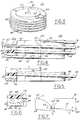
- Figure 1 shows a fuel pump according to the present invention mounted within an automotive fuel tank.
- Figure 2 is a cross-sectional view of a fuel pump according to the present invention.
- Figure 3 is a perspective of a helically shaped pumping element according to the present invention.
- Figure 4 is a side view of a helically shaped pumping element according to the present invention showing the leading edge, the trailing edge, and a lip on the radially outermost portion of the pumping side of the pumping element.
- Figure 5 is a partially cut-away view of the helically shaped pumping element of Figure 4 rotated 90° counterclockwise about an axis through the centre of the pumping element approximately perpendicular to the direction of the blades around the pumping element and showing the inlet section of the pumping element.
- Figure 6 is an enlargement of the inlet section of Figure 5 showing the inlet area as defined by the first turn pumping face, the hub on which the blade is mounted, the back side of the second turn, and an inner face of the inlet end of the pump housing,
- Figure 7 is a partial cross-sectional view of the leading edge of the helically shaped impeller according to the present invention showing the involute shape of the leading edge pumping face.
- Figure 8 is a plan view of a helically shaped pumping element according to the present invention.
- Figure 9 is a section view along line 9-9 of Figure 8 of the leading edge of a helically shaped pumping element according to the present invention at a radially outer lip portion of the pumping blade.
- Figure 10 is a section view along line 10-10 of Figure 8 of the leading edge of a helically shaped pumping element according to the present invention at a radially inner portion of the pumping blade.
- Figure 11 is a partially cut-away view of the helically shaped pumping element of Figure 4 rotated 90° clockwise about an axis through the centre of the pumping element approximately perpendicular to the direction of the blades around the pumping element and showing the outlet section of the pumping element.
- Figure 12 is a back view of the helically shaped pumping element of Figure 4 rotated 180° about an axis through the centre of the pumping element approximately perpendicular to the direction of the blades around the pumping element.
- Figure 13a is a cross-sectional view of a prior art pumping mechanism showing a regenerative turbine impeller within a pumping chamber.
- Figure 13b is a cross-sectional view of a prior art pumping mechanism having gerotor within a pumping chamber.
- Figure 13c is a cross-sectional view of a pumping mechanism according to the present invention having a helically shaped impeller.
- Referring now to Figure 1, a
fuel pump 10 according to the present invention is shown mounted in a known manner in anautomotive fuel tank 12. Afuel line 16 connectspump 10 with engine 14. Fuel is drawn bypump 10 fromtank 12 throughfilter 18 and is pumped throughfuel line 16 to engine 14. - A cross-sectional view of
fuel pump 10 is shown in Figure 2.Fuel pump 10 has ahousing 20 for containing its inner components. Amotor 22, preferably an electric motor, is mounted withinmotor space 23 for rotating ashaft 24 extending therefrom in the direction ofend portion 32.Motor 22 is preferably driven by brushed or brushless means, but is not confined to such. A helically shaped rotary pumping element, preferably ahelical impeller 26, is fitted onshaft 24near end portion 32.Impeller 26 has a central axis which is coincident with the axis ofshaft 24.End portion 32 hasinlet 30 therein running generally in the direction of an axis parallel toshaft 24.Helical impeller 26 comprises ahelical blade 45 having a leadingedge 46 which travels in an approximately perpendicular direction to an axis throughinlet 30 and parallel toshaft 24.Shaft 24 passes through shaft opening 42 inimpeller 26, intorecess 31 ofend portion 32, and abuts thrustbutton 33. A thrust bearing (not shown) can be used in place of a thrust button.Shaft 24 is journalled within bearing 28. - Pressurised fuel is discharged from
impeller 26 tomotor space 23 and coolsmotor 22 while passing over it to pumpoutlet 34 at an end ofpump 10 axially oppositeinlet 30. The fuel also cleans and coolsmotor commutator 27, motorupper bearings 29, and motor brushes (not shown). Check valve 38 opens to lower system pressure intotank 12 shouldmotor space 23 become overpressurised. - A perspective view of
impeller 26, preferably having an outer diameter of approximately 38 millimetres, is shown in Figure 3.Impeller 26 has a generallycylindrical hub 40 with acentral axis 43 therethrough.Shaft opening 42 extends throughhub 40 coaxially withcentral axis 43. Pumpingblade 45, shown with five (5) blade turns 44, extends fromhub 40. Preferably,impeller 26 has at least two (2) turns, but may have any number within the physical limitations imposed by the size ofpump 10. Eachturn 44 has a pumpingface 52 generally facingmotor 22 and aback face 54 generally facing inlet 30 (Figures 2 and 4).Pump 10 output pressure is directly proportional the number of blade turns 44 onimpeller 26. - Blade turns 44 extend radially outward from
wall 56 ofhub 40 and helically wind aroundcentral axis 43, as is more clearly seen in Figure 4. The helical turn angle, α, betweenlines Line 60 is perpendicular tocentral axis 43 andline 62 is parallel withblade turn 44a. Angle α preferably is approximately 2°, butsatisfactory pump 10 performance is achieved between 1.5° and 4°. For low pressure applications, angle α can range up to 30°, but is limited by the physical size ofpump 10 as the higher angle α becomes, thelonger impeller 26 must be to accommodate angled blade turns 44. - Still referring to Figure 4,
blade 45 has involute shaped leadingedge 46 designed to efficiently funnel fuel onto pumpingface 52. The axial width ofblade 45 narrows onback face 54 toward trailingedge 50, as seen at the top of Figure 4, from the width atblade section 76 to the width atblade section 74.Lip 48, on a radially outermost circumference of pumpingface 52 ofblade 45, forms a trough to prevent fuel splash-back between blade turns 44. - Figure 5 is a partially cut-away side view of
impeller 26, rotated 90° counterclockwise aboutcentre axis 43, showingimpeller inlet 49 at leadingedge 46. As better seen in Figure 6,impeller inlet 49 is bounded byhub 56, pumpingface 52 of first turn 44b, back face 54 ofsecond turn 44c, andline 58, which is parallel to pump housing 20 (not shown).Impeller inlet 49 preferably has a cross-sectional area of approximately between 2 mm² and 25 mm², and leads to impeller pumpingchannel 35 which runs circumferentially aroundhub 40 betweenblades 44, as is best seen in Figure 4.Impeller pumping channel 35 has an essentially constant cross-sectional area, A, preferably equal to the cross-sectional area ofimpeller inlet 49. - The design parameters of
impeller 26influence pump 10 flowrate and output pressure. For example, it is believed that pump 10 output pressure increases as the average turn distance, D', increases (Figure 5). Distance D' is the average of distances D₁, the distance fromcentre axis 43 to the outermost circumference ofblades 44 along a line perpendicular tocentre axis 43, and D₂, the distance fromcentre axis 43 tohub 56 along a line perpendicular tocentre axis 43. In addition, flowrate throughpump 10 is influenced byseveral impeller 26 variables, as shown in the following equation:
where - Q =
- fuel flowrate;
- A =
- the pumping channel cross-sectional area;
- D₁=
- the distance to the outermost point of the impeller from the center axis;
- D₂=
- the distance to the hub of the impeller from the center axis;
- RPM=
- revolutions per minute of the impeller;
- α =
- the impeller blade helical angle.
- Thus, pump 10 flowrate varies with the size of pumping channel cross-sectional area, A,
impeller blade 45 helical angle, α, and pump 10 speed (RPMs).Motor 22 typically rotatesshaft 24 andimpeller 26 at speeds approximately between 500 rpm and 15,000 rpm. - A partial cross-sectional view of the involute shape of leading
edge 46 offirst turn 44 ofblade 45 is shown in Figure 7. Leadingedge 46 is shaped such that the angle β betweenline 66, which is perpendicular to a line 64 that is tangent to leadingedge 46, andinner face 68 ofend portion 32 is between approximately 3° and 8°, and preferably is approximately 5°. Pumpingface 52 ofblade 44 near leadingedge 46 is shaped such that the distance E frominner face 68 ofend portion 32 to leadingedge 46 is not more than twenty percent (20%) of the distance B frominner face 68 ofend portion 32 to a point C on pumpingface 52 at which the cross-sectional area ofimpeller inlet 49 begins to remain constant for at least one turn ofblade 45. - Figure 8 is a plan view of
impeller 26showing blade 45 attached tohub 40, both of which are concentric withshaft opening 42. Figure 9 is a cross-sectional view along line 9-9 of Figure 8 at a radially outer portion ofblade 45 throughlip 48. Figure 10 is a cross-sectional view along line 10-10 of Figure 8 through leadingedge 46 ofimpeller 26 at a radially inner portion ofblade 45 showing thesmaller blade 45 thicknessrelative lip 48 thickness as shown in Figure 9. - Figure 11 shows a partially cut-away view of
impeller 26 rotated 90° clockwise aboutcenter axis 43 from the position shown in Figure 4.Impeller outlet 78 is bounded byhub 56, pumpingface 52 of second-to-last blade turn 44d, back face 54 oflast turn 44e, andline 79, which is parallel to pump housing 20 (not shown). The cross-sectional area ofimpeller outlet 78, which preferably is larger than the cross-sectional area ofimpeller pumping channel 35, is preferably approximately between 3 mm² and 36 mm². This increase in cross-sectional area is accomplished by reducing the axial width ofblade 45 onback face 54 toward trailingedge 50, as seen at the top of Figure 4, from the width atblade section 76 to the width atblade section 74. - Figure 12 is a back view of
impeller 26 rotated 180° aboutcenter axis 43 from the view of Figure 4 showingimpeller pumping channel 35 betweenblades 44. - In operation, as
motor 22 rotatesimpeller 26 onshaft 24, fuel is drawn fromtank 12 throughinlet 30, is scooped up by leadingedge 46 intoimpeller inlet 49, and is propelled axially towardmotor 22 and radially towardpump housing 20 throughimpeller pumping channel 35. Rotation ofimpeller 26 imparts both an axial force component and a radial force component to the fuel due to the helical shape ofblade 45 aroundhub 40. When the fuel reachesimpeller outlet 78, fuel pressure increases atimpeller outlet 78 due to the increased cross-sectional area, as discussed above, and flows intomotor space 23. -
Impeller 26 is preferably injection moulded using glass filled polymers or multi-property polymers (ter-polymers) or other plastic, thermoplastic, or nonplastic materials known to those skilled in the art and suggested by this disclosure. Alternatively,impeller 26 can be machined out of lightweight aluminium using computerised numeric control (CNC) methods.
Claims (10)
- A fuel pump for supplying fuel from a fuel tank to an automotive engine, comprising:
a pump housing(20);
a motor (22) mounted within a motor chamber (23) within said housing (20) and having a shaft (24) extending therefrom;
an inlet (30) in an end of said housing in fluid communication with said tank; and
a helically shaped pumping element (26) fitted to said shaft (24) between said inlet (30) and said motor (22) for pumping fuel in a generally axial direction from said tank (12), through said inlet (30), to said motor chamber (23), and to an outlet (34) leading to said engine, with said pumping (26) element being toleranced so as not to contact said pump housing. - A fuel pump according to Claim 1 wherein said helically shaped pumping element comprises a helical blade making at least two turns around a longitudinal axis through said shaft, and wherein said at least two turns have a pumping face generally facing said motor and a back face generally facing said inlet.
- A fuel pump according to Claim 1 wherein said pump housing has an end portion with said inlet therein running generally in the direction of an axis parallel to said shaft, and wherein said helically shaped pumping element comprises a helical blade having a leading edge which travels in an approximately perpendicular direction to an axis through said inlet and parallel to said shaft.
- A fuel pump according to Claim 3 wherein said leading edge is shaped such that the angle between a line perpendicular to a line tangent to said leading edge and an inner face of said end portion is approximately 5°.
- A fuel pump according to Claim 2 wherein fuel flows from said tank, through said inlet, and is scooped by said leading edge into an impeller inlet in said helically shaped pumping element defined by said leading edge, said cover portion, a hub fitted to said shaft and to which said blade is attached, and a back side of a blade turn adjacent said inlet blade turn, said back side of said blade generally facing said inlet.
- A fuel pump according to Claim 5 wherein said leading edge is shaped such that the distance from an inner face of said end portion to said leading edge is not more than twenty percent (20%) of the distance from said inner face of said end portion to a point on said pumping face of said first turn of said blade at which the cross-sectional areas of said impeller inlet begins to remain constant for at least one blade turn.
- A fuel pump according to Claim 6 wherein said impeller inlet has a cross-sectional area of approximately 2 mm² to 25 mm².
- A fuel pump according to Claim 3 wherein said blade has a pumping side generally facing said motor, said pumping side having a lip along the radially outermost portion of said blade for reducing blade tip losses.
- A fuel pump according to Claim 2 wherein said blade has a trailing edge of reduced thickness located at an axially opposite end of said blade from said leading edge.
- A fuel pump according to Claim 2 wherein said at least two turns of said blade are angled between approximately 1.5° to 4° from a line perpendicular to said shaft.
Applications Claiming Priority (2)
| Application Number | Priority Date | Filing Date | Title |
|---|---|---|---|
| US162566 | 1988-03-01 | ||
| US08/162,566 US5487650A (en) | 1993-12-07 | 1993-12-07 | Automotive fuel pump with helical impeller |
Publications (2)
| Publication Number | Publication Date |
|---|---|
| EP0657640A1 true EP0657640A1 (en) | 1995-06-14 |
| EP0657640B1 EP0657640B1 (en) | 1998-12-23 |
Family
ID=22586180
Family Applications (1)
| Application Number | Title | Priority Date | Filing Date |
|---|---|---|---|
| EP94307695A Expired - Lifetime EP0657640B1 (en) | 1993-12-07 | 1994-10-19 | Automotive fuel pump with helical impeller |
Country Status (4)
| Country | Link |
|---|---|
| US (1) | US5487650A (en) |
| EP (1) | EP0657640B1 (en) |
| JP (1) | JPH07189844A (en) |
| DE (1) | DE69415485T2 (en) |
Cited By (5)
| Publication number | Priority date | Publication date | Assignee | Title |
|---|---|---|---|---|
| FR2818320A1 (en) * | 2000-12-14 | 2002-06-21 | Marwal Systems | FUEL PUMP DEVICE FOR A MOTOR VEHICLE TANK |
| FR2818321A1 (en) * | 2000-12-14 | 2002-06-21 | Marwal Systems | Fuel delivery system, for vehicles, has brushless suction pump fitted with fine filter, upstream of pump. |
| US6733249B2 (en) | 2001-05-17 | 2004-05-11 | Delphi Technologies, Inc. | Multi-stage internal gear fuel pump |
| US6758656B2 (en) * | 2001-05-17 | 2004-07-06 | Delphi Technologies, Inc. | Multi-stage internal gear/turbine fuel pump |
| EP3650192A1 (en) * | 2018-11-12 | 2020-05-13 | TI Automotive Technology Center GmbH | Helical fuel pumping element |
Families Citing this family (13)
| Publication number | Priority date | Publication date | Assignee | Title |
|---|---|---|---|---|
| US6068454A (en) * | 1998-04-06 | 2000-05-30 | Ford Motor Company | Fuel pump with helical impeller |
| US6468029B2 (en) | 2001-02-21 | 2002-10-22 | George J. Teplanszky | Pump device |
| US6767181B2 (en) | 2002-10-10 | 2004-07-27 | Visteon Global Technologies, Inc. | Fuel pump |
| US6984099B2 (en) * | 2003-05-06 | 2006-01-10 | Visteon Global Technologies, Inc. | Fuel pump impeller |
| US20040258545A1 (en) * | 2003-06-23 | 2004-12-23 | Dequan Yu | Fuel pump channel |
| US7008174B2 (en) * | 2004-05-10 | 2006-03-07 | Automotive Components Holdings, Inc. | Fuel pump having single sided impeller |
| US7267524B2 (en) * | 2004-05-10 | 2007-09-11 | Ford Motor Company | Fuel pump having single sided impeller |
| US7931448B2 (en) * | 2006-08-01 | 2011-04-26 | Federal Mogul World Wide, Inc. | System and method for manufacturing a brushless DC motor fluid pump |
| US20080038135A1 (en) * | 2006-08-10 | 2008-02-14 | White Drive Products, Inc. | Corrosion resistant hydraulic motor |
| US7847457B2 (en) | 2007-05-09 | 2010-12-07 | Federal-Mogul World Wide, Inc | BLDC motor assembly |
| WO2018028205A1 (en) * | 2016-08-06 | 2018-02-15 | 中山大洋电机股份有限公司 | Wind wheel and blower using the same |
| US12196213B2 (en) * | 2019-04-10 | 2025-01-14 | Af5, Llc | Activity pool axial flow pump |
| DE102020206493A1 (en) * | 2020-05-25 | 2021-11-25 | Hyundai Motor Company | Fuel pump for a liquid fuel injection system of a motor vehicle |
Citations (4)
| Publication number | Priority date | Publication date | Assignee | Title |
|---|---|---|---|---|
| US2846952A (en) * | 1955-12-27 | 1958-08-12 | Hydro Aire Inc | Fuel pump |
| US2887959A (en) * | 1951-02-17 | 1959-05-26 | Thompson Ramo Wooldridge Inc | Submerged booster pump |
| US5015156A (en) * | 1989-06-19 | 1991-05-14 | Scholz Daniel E | Aircraft fuel pump |
| DE4123384A1 (en) * | 1991-07-15 | 1993-01-21 | Leistritz Ag | Non-pulsating pump for volatile fuels - has electric driven pair of meshing spiral shafts inside motor housing |
Family Cites Families (12)
| Publication number | Priority date | Publication date | Assignee | Title |
|---|---|---|---|---|
| US2925043A (en) * | 1960-02-16 | Booster pump | ||
| GB354551A (en) * | 1929-08-08 | 1931-08-13 | Siemens-Bauunion G.M.B.H. Kommanditgesellschaft | |
| US2760437A (en) * | 1951-02-24 | 1956-08-28 | Thompson Prod Inc | Submerged booster pump |
| US2845871A (en) * | 1955-05-20 | 1958-08-05 | Borg Warner | Mixed flow booster pump |
| US3107626A (en) * | 1962-01-08 | 1963-10-22 | Borg Warner | Booster pumps |
| US3431855A (en) * | 1967-03-06 | 1969-03-11 | Boris Afanasievich Kazantsev | Screw pump |
| US3522997A (en) * | 1968-07-01 | 1970-08-04 | Rylewski Eugeniusz | Inducer |
| US3602604A (en) * | 1969-10-15 | 1971-08-31 | Bernard M Ronellenfitch | Pump construction |
| US4481020A (en) * | 1982-06-10 | 1984-11-06 | Trw Inc. | Liquid-gas separator apparatus |
| US4545742A (en) * | 1982-09-30 | 1985-10-08 | Dunham-Bush, Inc. | Vertical axis hermetic helical screw rotary compressor with discharge gas oil mist eliminator and dual transfer tube manifold for supplying liquid refrigerant and refrigerant vapor to the compression area |
| DE3913148C1 (en) * | 1989-04-21 | 1990-10-04 | Karl-August 7070 Schwaebisch Gmuend De Radlik | |
| US5324177A (en) * | 1989-05-08 | 1994-06-28 | The Cleveland Clinic Foundation | Sealless rotodynamic pump with radially offset rotor |
-
1993
- 1993-12-07 US US08/162,566 patent/US5487650A/en not_active Expired - Lifetime
-
1994
- 1994-10-19 EP EP94307695A patent/EP0657640B1/en not_active Expired - Lifetime
- 1994-10-19 DE DE69415485T patent/DE69415485T2/en not_active Expired - Fee Related
- 1994-11-09 JP JP6275169A patent/JPH07189844A/en active Pending
Patent Citations (4)
| Publication number | Priority date | Publication date | Assignee | Title |
|---|---|---|---|---|
| US2887959A (en) * | 1951-02-17 | 1959-05-26 | Thompson Ramo Wooldridge Inc | Submerged booster pump |
| US2846952A (en) * | 1955-12-27 | 1958-08-12 | Hydro Aire Inc | Fuel pump |
| US5015156A (en) * | 1989-06-19 | 1991-05-14 | Scholz Daniel E | Aircraft fuel pump |
| DE4123384A1 (en) * | 1991-07-15 | 1993-01-21 | Leistritz Ag | Non-pulsating pump for volatile fuels - has electric driven pair of meshing spiral shafts inside motor housing |
Cited By (6)
| Publication number | Priority date | Publication date | Assignee | Title |
|---|---|---|---|---|
| FR2818320A1 (en) * | 2000-12-14 | 2002-06-21 | Marwal Systems | FUEL PUMP DEVICE FOR A MOTOR VEHICLE TANK |
| FR2818321A1 (en) * | 2000-12-14 | 2002-06-21 | Marwal Systems | Fuel delivery system, for vehicles, has brushless suction pump fitted with fine filter, upstream of pump. |
| US6733249B2 (en) | 2001-05-17 | 2004-05-11 | Delphi Technologies, Inc. | Multi-stage internal gear fuel pump |
| US6758656B2 (en) * | 2001-05-17 | 2004-07-06 | Delphi Technologies, Inc. | Multi-stage internal gear/turbine fuel pump |
| EP3650192A1 (en) * | 2018-11-12 | 2020-05-13 | TI Automotive Technology Center GmbH | Helical fuel pumping element |
| WO2020100037A1 (en) * | 2018-11-12 | 2020-05-22 | Ti Automotive Technology Center Gmbh | Helical fuel conveying element |
Also Published As
| Publication number | Publication date |
|---|---|
| JPH07189844A (en) | 1995-07-28 |
| EP0657640B1 (en) | 1998-12-23 |
| US5487650A (en) | 1996-01-30 |
| DE69415485T2 (en) | 1999-05-12 |
| DE69415485D1 (en) | 1999-02-04 |
Similar Documents
| Publication | Publication Date | Title |
|---|---|---|
| EP0657640B1 (en) | Automotive fuel pump with helical impeller | |
| US5407318A (en) | Regenerative pump and method of manufacturing impeller | |
| US5328325A (en) | Peripheral pump, particularly for delivering fuel from a storage tank to the internal combustion engine of a motor vehicle | |
| US5762469A (en) | Impeller for a regenerative turbine fuel pump | |
| US7037066B2 (en) | Turbine fuel pump impeller | |
| EP0931927B1 (en) | Impeller of motor-driven fuel pump | |
| US5265997A (en) | Turbine-vane fuel pump | |
| US6824361B2 (en) | Automotive fuel pump impeller with staggered vanes | |
| JPH0631633B2 (en) | Turbin type fuel pump | |
| US6527506B2 (en) | Pump section for fuel pump | |
| US5660536A (en) | High capacity simplified sea water pump | |
| CA2285797A1 (en) | Fuel pump chamber with contamination control | |
| US5375975A (en) | Fuel pump pre-swirl inlet channel | |
| US20030118438A1 (en) | Fuel pump | |
| US6688844B2 (en) | Automotive fuel pump impeller | |
| CN100339590C (en) | Turbine fuel pump | |
| US6669437B2 (en) | Regenerative fuel pump with leakage prevent grooves | |
| EP1045148B1 (en) | Automotive fuel pump with a high efficiency vapor venting system | |
| US20020071758A1 (en) | Impeller for fuel pump | |
| EP0784158B1 (en) | Regenerative pump | |
| US5364238A (en) | Divergent inlet for an automotive fuel pump | |
| US20030180160A1 (en) | Gear feed pump | |
| CN1049476C (en) | Blade used in fluid mechanism and fluid mechanism using same | |
| US5261783A (en) | Kinetic pump having a centerless impeller | |
| CN2632357Y (en) | Spiral sealer for pump |
Legal Events
| Date | Code | Title | Description |
|---|---|---|---|
| PUAI | Public reference made under article 153(3) epc to a published international application that has entered the european phase |
Free format text: ORIGINAL CODE: 0009012 |
|
| AK | Designated contracting states |
Kind code of ref document: A1 Designated state(s): DE FR GB |
|
| 17P | Request for examination filed |
Effective date: 19951106 |
|
| 17Q | First examination report despatched |
Effective date: 19970502 |
|
| GRAG | Despatch of communication of intention to grant |
Free format text: ORIGINAL CODE: EPIDOS AGRA |
|
| GRAG | Despatch of communication of intention to grant |
Free format text: ORIGINAL CODE: EPIDOS AGRA |
|
| GRAH | Despatch of communication of intention to grant a patent |
Free format text: ORIGINAL CODE: EPIDOS IGRA |
|
| GRAH | Despatch of communication of intention to grant a patent |
Free format text: ORIGINAL CODE: EPIDOS IGRA |
|
| GRAA | (expected) grant |
Free format text: ORIGINAL CODE: 0009210 |
|
| AK | Designated contracting states |
Kind code of ref document: B1 Designated state(s): DE FR GB |
|
| REF | Corresponds to: |
Ref document number: 69415485 Country of ref document: DE Date of ref document: 19990204 |
|
| ET | Fr: translation filed | ||
| PLBE | No opposition filed within time limit |
Free format text: ORIGINAL CODE: 0009261 |
|
| STAA | Information on the status of an ep patent application or granted ep patent |
Free format text: STATUS: NO OPPOSITION FILED WITHIN TIME LIMIT |
|
| 26N | No opposition filed | ||
| PGFP | Annual fee paid to national office [announced via postgrant information from national office to epo] |
Ref country code: FR Payment date: 20001018 Year of fee payment: 7 |
|
| REG | Reference to a national code |
Ref country code: GB Ref legal event code: IF02 |
|
| PG25 | Lapsed in a contracting state [announced via postgrant information from national office to epo] |
Ref country code: FR Free format text: LAPSE BECAUSE OF NON-PAYMENT OF DUE FEES Effective date: 20020628 |
|
| REG | Reference to a national code |
Ref country code: FR Ref legal event code: ST |
|
| PGFP | Annual fee paid to national office [announced via postgrant information from national office to epo] |
Ref country code: GB Payment date: 20030929 Year of fee payment: 10 |
|
| PGFP | Annual fee paid to national office [announced via postgrant information from national office to epo] |
Ref country code: DE Payment date: 20031010 Year of fee payment: 10 |
|
| PG25 | Lapsed in a contracting state [announced via postgrant information from national office to epo] |
Ref country code: GB Free format text: LAPSE BECAUSE OF NON-PAYMENT OF DUE FEES Effective date: 20041019 |
|
| PG25 | Lapsed in a contracting state [announced via postgrant information from national office to epo] |
Ref country code: DE Free format text: LAPSE BECAUSE OF NON-PAYMENT OF DUE FEES Effective date: 20050503 |
|
| GBPC | Gb: european patent ceased through non-payment of renewal fee |
Effective date: 20041019 |