EP0657269A1 - Injection molding apparatus with perpendicular hot tip gates - Google Patents
Injection molding apparatus with perpendicular hot tip gates Download PDFInfo
- Publication number
- EP0657269A1 EP0657269A1 EP94118892A EP94118892A EP0657269A1 EP 0657269 A1 EP0657269 A1 EP 0657269A1 EP 94118892 A EP94118892 A EP 94118892A EP 94118892 A EP94118892 A EP 94118892A EP 0657269 A1 EP0657269 A1 EP 0657269A1
- Authority
- EP
- European Patent Office
- Prior art keywords
- gates
- parting line
- extending
- nozzle
- manifold
- Prior art date
- Legal status (The legal status is an assumption and is not a legal conclusion. Google has not performed a legal analysis and makes no representation as to the accuracy of the status listed.)
- Granted
Links
- 238000001746 injection moulding Methods 0.000 title claims abstract description 14
- 108091092889 HOTTIP Proteins 0.000 title abstract description 9
- 239000000155 melt Substances 0.000 claims description 20
- 238000010008 shearing Methods 0.000 abstract description 6
- 238000001816 cooling Methods 0.000 description 8
- 238000010438 heat treatment Methods 0.000 description 5
- 238000007789 sealing Methods 0.000 description 4
- 239000000498 cooling water Substances 0.000 description 3
- 238000000465 moulding Methods 0.000 description 3
- 238000005086 pumping Methods 0.000 description 2
- 229910000831 Steel Inorganic materials 0.000 description 1
- 230000000694 effects Effects 0.000 description 1
- 238000002347 injection Methods 0.000 description 1
- 239000007924 injection Substances 0.000 description 1
- 239000000463 material Substances 0.000 description 1
- 238000012986 modification Methods 0.000 description 1
- 230000004048 modification Effects 0.000 description 1
- 238000012856 packing Methods 0.000 description 1
- 238000000926 separation method Methods 0.000 description 1
- 239000010959 steel Substances 0.000 description 1
- 230000036962 time dependent Effects 0.000 description 1
Images
Classifications
-
- B—PERFORMING OPERATIONS; TRANSPORTING
- B29—WORKING OF PLASTICS; WORKING OF SUBSTANCES IN A PLASTIC STATE IN GENERAL
- B29C—SHAPING OR JOINING OF PLASTICS; SHAPING OF MATERIAL IN A PLASTIC STATE, NOT OTHERWISE PROVIDED FOR; AFTER-TREATMENT OF THE SHAPED PRODUCTS, e.g. REPAIRING
- B29C45/00—Injection moulding, i.e. forcing the required volume of moulding material through a nozzle into a closed mould; Apparatus therefor
- B29C45/17—Component parts, details or accessories; Auxiliary operations
- B29C45/26—Moulds
- B29C45/27—Sprue channels ; Runner channels or runner nozzles
- B29C45/2735—Sprue channels ; Runner channels or runner nozzles for non-coaxial gates, e.g. for edge gates
Definitions
- This invention relates generally to injection molding and more particularly to apparatus wherein nozzles extend diagonally from an elongated manifold to convey melt to gates extending parallel to the parting line.
- Injection molding simultaneously through a number of gates to a number of different cavities is well known in the art and is referred to as multi-cavity molding. It is well known to do this using a number of hot tip gated nozzles to convey melt out from a common melt distribution manifold or using a single edge gated nozzle to convey melt to a number of surrounding gates. Examples of edge gated nozzles are shown in the applicants' U.S. Patent Number 4,344,750 which issued August 17, 1982 and in Figure 4 of U.S. Patent Number 5,217,730 to Teng which issued June 8, 1993. These configurations have the advantage that the gates extend parallel to the parting line or perpendicular to the direction of mold opening and thus provide very clean shearing at the gate when the parts are demolded from the cavities.
- the invention provides an injection molding apparatus having a plurality of heated nozzles extending from a common elongated manifold with a melt passage inlet to convey melt from the melt passage inlet to a plurality of gates, each gate extending through a mold to a separate cavity extending from a common parting line, the parting line extending substantially perpendicular to the melt passage inlet, each nozzle being seated in a well in the mold and having a longitudinal axis, a rear end abutting against the manifold, and a pointed tip aligned with a respective one of the gates, having the improvement wherein the gates extend substantially parallel to the parting line, the manifold has at least one longitudinally extending diagonal surface against which the rear ends of the nozzles abut, whereby each nozzle extends forwardly and outwardly from the manifold at a first predetermined angle to the parting line, the pointed tip of each nozzle extending outwardly at a second predetermined angle to the longitudinal
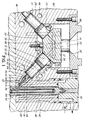
- Figure 1 shows a portion of a multi-cavity injection molding system or apparatus having several steel nozzles 10 extending from a melt distribution manifold 12 to convey pressurized plastic melt through a melt passage 14 to respective gates 16 leading to different cavities 18 in the mold 20.
- the melt distribution manifold 12 has a suitable elongated shape with a pair of diagonal surfaces 22, 24 extending longitudinally along it. While only two nozzles 10 are seen, there are several nozzles spaced in a row 26, 28 along each of the diagonal surfaces 22, 24.
- the melt passage 14 extends from a common inlet 30 in an inlet portion 32 of the melt distribution manifold 12 and branches in the manifold 12 to a separate arm 34 which extends in alignment with a melt bore 36 extending through each of the nozzles 10.
- the mold 20 is shown including only a nozzle and cavity retainer plate 38, cavity insert 40, cavity insert retainer plate 42, and core insert 44.
- Other molds may include a variety of additional plates or parts depending upon the application.
- the nozzle and cavity retainer plate 38 is cooled by pumping cooling water through cooling channels 46. Cooling is provided around each cavity 18 by pumping cooling water through a cooling conduit 48 with alternate portions extending forwardly and rearwardly on an angle to form a cooling circuit around the cavity 18. Cooling is also provided by cooling water flowing through a central cooling tube 50 extending in the core insert 44.
- Each nozzle 10 is seated in an opening 52 in the nozzle plate 38 with its rear end 54 abutting against one of the diagonal surfaces 22, 24 running along the elongated manifold 12.
- the nozzles 10 extend forwardly and outwardly from the manifold 12 with a longitudinal axis 56 extending at the same angle A to the common parting line 58 between the cavities 18 as the diagonal surfaces 22, 24 face.
- the angle A is substantially 45°, although in other embodiments the nozzles 10 can extend diagonally on some other suitable angle as described further below.
- Each nozzle 10 has a rear collar portion 60, a central cylindrical locating and sealing flange 62, and a forward nose portion 64.
- the locating and sealing flange 62 seals and locates in the opening 52 with an insulative air space 68 between the angled inner surface 70 of the opening 52 and the outer surface 72 of the locating flange 62.
- the insulative air space 68 ensures there is sufficient thermal separation between the cooled nozzle and cavity retainer plate 38 and the nozzle 10 which is heated by an integral electrical heating element 74.
- the heating element 74 extends around the melt bore 36 from an external terminal 76 near the rear end 54 and has a forward end 78 which extends centrally into the forward nose portion 64 of the nozzle 10.
- the melt bore 36 through the nozzle 10 has a central portion 78 which extends forwardly from the rear end 54 and a diagonal portion 80 which extends outwardly to a space 82 surrounding the forward nose portion 64.
- the locating and sealing flange 62 has a seal 84 which fits against the angled inner surface 70 of the opening 52 to prevent pressurized melt escaping from the space 82 around the forward nose portion 64 into the insulative air space 68 around the locating and sealing flange 62.
- the nozzles 10 are secured in place in the openings 52 in the nozzle and cavity retainer plate 38 by the elongated manifold 12.
- the manifold 12 is, in turn, held securely in place between a retaining plate 86 and a locating ring 88 by mounting screws 90.
- the melt distribution manifold 12 which can be heated by an integral electrical heating element (not shown) is mounted with an insulative air space 92 extending between it and the adjacent cooled nozzle and cavity retainer plate 38.
- the parting line 58 extends perpendicularly to the melt passage inlet 30 in the inlet portion 32 of the manifold and the mold opens in a direction perpendicular to the parting line 58.
- the walls 94 of the cavities 18 are also shown extending perpendicularly to the parting line 58, it is well known in the art that they must extend at a draft angle of from 0.5° to 5° from perpendicular to facilitate demolding from the cavities 18. While this draft has been disregarded to facilitate the following discussion, in actual fact it is well known that allowance must be made for it in determining the actual orientation of the cavity walls 94 and gates 16.
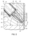
- the forward nose portion 64 of each nozzle 10 has a pointed tip 96 which extends in alignment with one of the gates 16.
- the pointed tip 96 extends outwardly at an angle B to the longitudinal axis 56 of the nozzle 10.
- the angle B is substantially 45° which is the same as angle A at which the longitudinal axis 56 of the nozzle 10 extends to provide that the pointed tips 96 and gates 16 extend in a direction substantially parallel to the parting line 58.
- the gates 16 extend perpendicular to the cavity wall 94 so the term "substantially parallel” is defined herein as allowing or providing for the required small draft angle referred to above.
- the angle B at which the pointed tips 96 extend also has to be 40° to result in the pointed tips 96 and gates 16 extending substantially parallel to the parting line 58.
- this has the advantage that the gates 16 extend substantially perpendicular to the direction of mold opening which produces very clean shearing at the gates 16.
- the injection molding system or apparatus is assembled as shown in Figures 1 and 2. Electrical power is applied to the heating element in the manifold 12 and to the heating elements 74 in the nozzles 10 to heat them to a predetermined operating temperature. Pressurized melt is applied from a molding machine (not shown) to the common inlet 30 to the melt passage 14 according to a predetermined molding cycle. The melt flows from the melt distribution manifold 12 through the nozzles 10 and gates 16 into the cavities 18. After the cavities 18 are filled and a suitable packing and cooling period has expired, injection pressure is released and the melt conveying system is decompressed to avoid possible stringing through the open gates 16. The mold 20 is then opened to demold the molded products.
- the orientation of the gates 16 substantially perpendicular to the direction of opening ensures very clean shearing at the gates 16 in line with the cavity wall 94.
- the mold 20 is closed and the cycle repeated continuously with a cycle time dependent upon the size of the cavities 18 and the type of material being molded.
Abstract
Description
- This invention relates generally to injection molding and more particularly to apparatus wherein nozzles extend diagonally from an elongated manifold to convey melt to gates extending parallel to the parting line.
- Injection molding simultaneously through a number of gates to a number of different cavities is well known in the art and is referred to as multi-cavity molding. It is well known to do this using a number of hot tip gated nozzles to convey melt out from a common melt distribution manifold or using a single edge gated nozzle to convey melt to a number of surrounding gates. Examples of edge gated nozzles are shown in the applicants' U.S. Patent Number 4,344,750 which issued August 17, 1982 and in Figure 4 of U.S. Patent Number 5,217,730 to Teng which issued June 8, 1993. These configurations have the advantage that the gates extend parallel to the parting line or perpendicular to the direction of mold opening and thus provide very clean shearing at the gate when the parts are demolded from the cavities. However, in addition to not being hot tip gated, they have the serious disadvantage for many larger cavity applications that the gates must be located relatively close together around the single nozzle between them. This space restriction limits the extent and location of cooling which can be provided adjacent the cavities which is important for fast cycles. It also limits the position of the gate on the cavity which is important in other situations to avoid undue core shift.
- An example of a number of hot tip gated nozzles extending out from a common melt distribution manifold is shown in U.S. Patent Number 4,768,945 to Schmidt et al. which issued September 6, 1988. While avoiding the above disadvantages of edge gating, this configuration has the disadvantage that the hot tip gates cannot be oriented to extend to a portion of the cavity wall which is perpendicular to the parting line to produce the shearing effect of edge gating. An example of nozzles extending diagonally outwardly from a common manifold is shown in Figure 28 of Plastverarbeiter
Volume 30 Number 2, 1979 pages 83 - 88 but it similarly has the disadvantage that the gates cannot extend parallel to the parting line and must be positioned at an angled portion of the cavity wall. Page 7 of Mold-Masters Limited Brochure E-CMSSN-11-90 Injection Molding with Compact Master-Shot shows nozzles for both angled hot tip gating and angled edge gating. However, none of the prior art shows the combined advantages of hot tip gating and shearing at the gates provided by the gates being oriented perpendicular to the direction of opening of the mold. - According, it is an object of the present invention to at least partially overcome the disadvantages of the prior art by providing injection molding apparatus for multi-cavity hot tip gating with the gates extending substantially parallel to the parting line.
- To this end, in one of its aspects, the invention provides an injection molding apparatus having a plurality of heated nozzles extending from a common elongated manifold with a melt passage inlet to convey melt from the melt passage inlet to a plurality of gates, each gate extending through a mold to a separate cavity extending from a common parting line, the parting line extending substantially perpendicular to the melt passage inlet, each nozzle being seated in a well in the mold and having a longitudinal axis, a rear end abutting against the manifold, and a pointed tip aligned with a respective one of the gates, having the improvement wherein the gates extend substantially parallel to the parting line, the manifold has at least one longitudinally extending diagonal surface against which the rear ends of the nozzles abut, whereby each nozzle extends forwardly and outwardly from the manifold at a first predetermined angle to the parting line, the pointed tip of each nozzle extending outwardly at a second predetermined angle to the longitudinal axis of the nozzle whereby the pointed tip is aligned with the respective one of the gates in a direction substantially parallel to the parting line.
- Further objects and advantages of the invention will appear from the following description taken together with the accompanying drawings.
-
- Figure 1 is a partial sectional view of a portion of a multi-cavity injection molding system showing apparatus according to a preferred embodiment of the invention, and
- Figure 2 is an enlarged sectional view of a portion of Figure 1 showing angles A and B.
- Reference is first made to Figure 1 which shows a portion of a multi-cavity injection molding system or apparatus having
several steel nozzles 10 extending from amelt distribution manifold 12 to convey pressurized plastic melt through amelt passage 14 torespective gates 16 leading todifferent cavities 18 in themold 20. Themelt distribution manifold 12 has a suitable elongated shape with a pair ofdiagonal surfaces nozzles 10 are seen, there are several nozzles spaced in arow diagonal surfaces melt passage 14 extends from acommon inlet 30 in aninlet portion 32 of themelt distribution manifold 12 and branches in themanifold 12 to aseparate arm 34 which extends in alignment with amelt bore 36 extending through each of thenozzles 10. - For ease of illustration, the
mold 20 is shown including only a nozzle andcavity retainer plate 38,cavity insert 40, cavityinsert retainer plate 42, andcore insert 44. Other molds may include a variety of additional plates or parts depending upon the application. The nozzle andcavity retainer plate 38 is cooled by pumping cooling water throughcooling channels 46. Cooling is provided around eachcavity 18 by pumping cooling water through acooling conduit 48 with alternate portions extending forwardly and rearwardly on an angle to form a cooling circuit around thecavity 18. Cooling is also provided by cooling water flowing through acentral cooling tube 50 extending in thecore insert 44. - Each
nozzle 10 is seated in anopening 52 in thenozzle plate 38 with its rear end 54 abutting against one of thediagonal surfaces elongated manifold 12. As best seen in Figure 2, thenozzles 10 extend forwardly and outwardly from themanifold 12 with alongitudinal axis 56 extending at the same angle A to thecommon parting line 58 between thecavities 18 as thediagonal surfaces nozzles 10 can extend diagonally on some other suitable angle as described further below. Eachnozzle 10 has arear collar portion 60, a central cylindrical locating and sealingflange 62, and aforward nose portion 64. The locating and sealingflange 62 seals and locates in the opening 52 with an insulative air space 68 between the angledinner surface 70 of the opening 52 and theouter surface 72 of the locatingflange 62. The insulative air space 68 ensures there is sufficient thermal separation between the cooled nozzle andcavity retainer plate 38 and thenozzle 10 which is heated by an integralelectrical heating element 74. Theheating element 74 extends around themelt bore 36 from anexternal terminal 76 near the rear end 54 and has aforward end 78 which extends centrally into theforward nose portion 64 of thenozzle 10. The melt bore 36 through thenozzle 10 has acentral portion 78 which extends forwardly from the rear end 54 and adiagonal portion 80 which extends outwardly to aspace 82 surrounding theforward nose portion 64. The locating and sealingflange 62 has aseal 84 which fits against the angledinner surface 70 of the opening 52 to prevent pressurized melt escaping from thespace 82 around theforward nose portion 64 into the insulative air space 68 around the locating and sealingflange 62. Thenozzles 10 are secured in place in theopenings 52 in the nozzle andcavity retainer plate 38 by theelongated manifold 12. Themanifold 12 is, in turn, held securely in place between aretaining plate 86 and a locatingring 88 by mountingscrews 90. Thus, themelt distribution manifold 12 which can be heated by an integral electrical heating element (not shown) is mounted with aninsulative air space 92 extending between it and the adjacent cooled nozzle andcavity retainer plate 38. - The
parting line 58 extends perpendicularly to themelt passage inlet 30 in theinlet portion 32 of the manifold and the mold opens in a direction perpendicular to theparting line 58. Although thewalls 94 of thecavities 18 are also shown extending perpendicularly to theparting line 58, it is well known in the art that they must extend at a draft angle of from 0.5° to 5° from perpendicular to facilitate demolding from thecavities 18. While this draft has been disregarded to facilitate the following discussion, in actual fact it is well known that allowance must be made for it in determining the actual orientation of thecavity walls 94 andgates 16. Theforward nose portion 64 of eachnozzle 10 has apointed tip 96 which extends in alignment with one of thegates 16. As best seen in Figure 2, thepointed tip 96 extends outwardly at an angle B to thelongitudinal axis 56 of thenozzle 10. In this embodiment, the angle B is substantially 45° which is the same as angle A at which thelongitudinal axis 56 of thenozzle 10 extends to provide that thepointed tips 96 andgates 16 extend in a direction substantially parallel to theparting line 58. Thegates 16 extend perpendicular to thecavity wall 94 so the term "substantially parallel" is defined herein as allowing or providing for the required small draft angle referred to above. If thediagonal surfaces manifold 12 are shaped so the rows ofnozzles 10 extend outwardly withangle A 40° then the angle B at which thepointed tips 96 extend also has to be 40° to result in thepointed tips 96 andgates 16 extending substantially parallel to theparting line 58. As mentioned above, this has the advantage that thegates 16 extend substantially perpendicular to the direction of mold opening which produces very clean shearing at thegates 16. - In use, the injection molding system or apparatus is assembled as shown in Figures 1 and 2. Electrical power is applied to the heating element in the
manifold 12 and to theheating elements 74 in thenozzles 10 to heat them to a predetermined operating temperature. Pressurized melt is applied from a molding machine (not shown) to thecommon inlet 30 to themelt passage 14 according to a predetermined molding cycle. The melt flows from the melt distribution manifold 12 through thenozzles 10 andgates 16 into thecavities 18. After thecavities 18 are filled and a suitable packing and cooling period has expired, injection pressure is released and the melt conveying system is decompressed to avoid possible stringing through theopen gates 16. Themold 20 is then opened to demold the molded products. As described above, the orientation of thegates 16 substantially perpendicular to the direction of opening ensures very clean shearing at thegates 16 in line with thecavity wall 94. After demolding, themold 20 is closed and the cycle repeated continuously with a cycle time dependent upon the size of thecavities 18 and the type of material being molded. - While the description of the injection molding apparatus according to the invention has been given with respect to a preferred embodiment, it will be evident that various other modifications are possible without departing from the scope of the invention as understood by those skilled in the art and as defined in the following claims.
Claims (4)
- The embodiments of the invention in which an exclusive property or privilege is claimed are defined as follows:
- In an injection molding apparatus having a plurality of heated nozzles extending from a common elongated manifold with a melt passage inlet to convey melt from the melt passage inlet to a plurality of gates, each gate extending through a mold to a separate cavity extending from a common parting line, the parting line extending substantially perpendicular to the melt passage inlet, each nozzle being seated in a well in the mold and having a longitudinal axis, a rear end abutting against the manifold, and a pointed tip aligned with a respective one of the gates, having the improvement wherein;
the gates extend substantially parallel to the parting line, the manifold has at least one longitudinally extending diagonal surface against which the rear ends of the nozzles abut, whereby each nozzle extends forwardly and outwardly from the manifold at a first predetermined angle to the parting line, the pointed tip of each nozzle extending outwardly at a second predetermined angle to the longitudinal axis of the nozzle, whereby the pointed tip is aligned with the respective one of the gates in a direction substantially parallel to the parting line. - Injection molding apparatus as claimed in claim 1 wherein the manifold has a pair of longitudinally extending diagonal surfaces, each diagonal surface facing forwardly and in opposite directions outwardly at the first predetermined angle to the parting line, the nozzles being spaced along both of the diagonal surfaces in two rows extending forwardly and in opposite directions outwardly at the first predetermined angle to the parting line.
- Injection molding apparatus as claimed in claim 2 wherein the first predetermined angle at which each nozzle extends to the parting line is substantially 45° and the second predetermined angle at which the pointed tip of each nozzle extends outwardly to the longitudinal axis of the nozzle is substantially 45°.
Applications Claiming Priority (3)
| Application Number | Priority Date | Filing Date | Title |
|---|---|---|---|
| CA002110438A CA2110438C (en) | 1993-12-01 | 1993-12-01 | Injection molding apparatus with perpendicular hot tip gates |
| CA2110438 | 1993-12-01 | ||
| US08/170,827 US5366370A (en) | 1993-12-01 | 1993-12-21 | Injection molding apparatus with perpendicular hot tip gates |
Publications (2)
| Publication Number | Publication Date |
|---|---|
| EP0657269A1 true EP0657269A1 (en) | 1995-06-14 |
| EP0657269B1 EP0657269B1 (en) | 1999-09-22 |
Family
ID=25676826
Family Applications (1)
| Application Number | Title | Priority Date | Filing Date |
|---|---|---|---|
| EP94118892A Expired - Lifetime EP0657269B1 (en) | 1993-12-01 | 1994-11-30 | Injection molding apparatus with perpendicular hot tip gates |
Country Status (4)
| Country | Link |
|---|---|
| US (1) | US5366370A (en) |
| EP (1) | EP0657269B1 (en) |
| JP (1) | JP3571090B2 (en) |
| DE (1) | DE4442667C2 (en) |
Cited By (2)
| Publication number | Priority date | Publication date | Assignee | Title |
|---|---|---|---|---|
| EP2199055A1 (en) * | 2008-12-17 | 2010-06-23 | Hans Schreck | Device for spraying plastic moulds |
| US11548195B2 (en) | 2020-10-22 | 2023-01-10 | Mold-Masters (2007) Limited | Angle gating injection molding apparatus |
Families Citing this family (7)
| Publication number | Priority date | Publication date | Assignee | Title |
|---|---|---|---|---|
| CA2164557C (en) * | 1995-12-06 | 2007-05-08 | Jobst Ulrich Gellert | Injection molding nozzle manifold |
| US5993190A (en) * | 1998-02-24 | 1999-11-30 | Illinois Tool Works Inc. | Injection molding system with improved pressure bushing |
| CA2471659A1 (en) * | 2003-06-20 | 2004-12-20 | Mold-Masters Limited | Injection molding manifold with multi-axis adjustable manifold blocks and nozzles |
| WO2012115614A2 (en) * | 2010-02-01 | 2012-08-30 | Husky Injection Molding Systems Ltd | Side gate nozzle assembly |
| CN102328381B (en) | 2010-06-16 | 2015-04-01 | 马斯特模具(2007)有限公司 | Edge-gated nozzle |
| US8899964B2 (en) * | 2012-03-16 | 2014-12-02 | Mold-Masters (2007) Limited | Edge-gated injection molding apparatus |
| JP6729588B2 (en) * | 2015-07-21 | 2020-07-22 | コニカミノルタ株式会社 | Molding die and method for manufacturing plate-shaped optical component |
Citations (2)
| Publication number | Priority date | Publication date | Assignee | Title |
|---|---|---|---|---|
| EP0124951A2 (en) * | 1983-05-06 | 1984-11-14 | van Noort, Jacob | Method, injection moulding machine and injection mould for producing holder shaped products, holder shaped products and hot runner system |
| EP0186413A2 (en) * | 1984-12-21 | 1986-07-02 | Tanner AG | Equipment for injection moulding of plastics |
Family Cites Families (3)
| Publication number | Priority date | Publication date | Assignee | Title |
|---|---|---|---|---|
| US4344750A (en) * | 1981-04-02 | 1982-08-17 | Gellert Jobst U | Edge gated injection molding system with hollow seals |
| CA1261573A (en) * | 1987-10-16 | 1989-09-26 | Harald H. Schmidt | Injection molding nozzle having grounded heating element brazed into pointed tip |
| US5217730A (en) * | 1992-05-04 | 1993-06-08 | Alex C. Teng | Multi-cavity injection molding heated nozzle |
-
1993
- 1993-12-21 US US08/170,827 patent/US5366370A/en not_active Expired - Lifetime
-
1994
- 1994-11-30 EP EP94118892A patent/EP0657269B1/en not_active Expired - Lifetime
- 1994-11-30 DE DE4442667A patent/DE4442667C2/en not_active Expired - Fee Related
- 1994-12-01 JP JP29858994A patent/JP3571090B2/en not_active Expired - Lifetime
Patent Citations (2)
| Publication number | Priority date | Publication date | Assignee | Title |
|---|---|---|---|---|
| EP0124951A2 (en) * | 1983-05-06 | 1984-11-14 | van Noort, Jacob | Method, injection moulding machine and injection mould for producing holder shaped products, holder shaped products and hot runner system |
| EP0186413A2 (en) * | 1984-12-21 | 1986-07-02 | Tanner AG | Equipment for injection moulding of plastics |
Non-Patent Citations (2)
| Title |
|---|
| GOLDBACH: "Heisskanal-Werkzeuge für die Verarbeitung "technischer" Thermoplaste", PLASTVERARBEITER, vol. 30, no. 2, 1979, SPEYER/RHEIN DE, pages 83 - 88 * |
| VOGEL: "Variationsmöglichkeiten moderner Heisskanalsysteme", PLASTVERARBEITER, vol. 40, no. 5, 1989, SPEYER/RHEIN DE, pages 130 - 131, XP000101057 * |
Cited By (2)
| Publication number | Priority date | Publication date | Assignee | Title |
|---|---|---|---|---|
| EP2199055A1 (en) * | 2008-12-17 | 2010-06-23 | Hans Schreck | Device for spraying plastic moulds |
| US11548195B2 (en) | 2020-10-22 | 2023-01-10 | Mold-Masters (2007) Limited | Angle gating injection molding apparatus |
Also Published As
| Publication number | Publication date |
|---|---|
| US5366370A (en) | 1994-11-22 |
| DE4442667C2 (en) | 2003-01-30 |
| JPH07195446A (en) | 1995-08-01 |
| DE4442667A1 (en) | 1995-06-08 |
| JP3571090B2 (en) | 2004-09-29 |
| EP0657269B1 (en) | 1999-09-22 |
Similar Documents
| Publication | Publication Date | Title |
|---|---|---|
| US5820899A (en) | Injection molding nozzle with edge gate inserts and sealing ring | |
| EP0681900B1 (en) | Injection molding nozzle with two removable inserts | |
| US6079972A (en) | Injection molding cooling core having spiral grooves | |
| US5387099A (en) | Injection molding valve member sealing bushing with a thin collar portion | |
| US5106291A (en) | Injection molding apparatus with heated valve member | |
| US5366369A (en) | Injection molding insert having an aligned pin and melt inlet | |
| CA2057438C (en) | Injection molding sealing collar with a central hot tip shaft | |
| US5494433A (en) | Injection molding hot tip side gate seal having a circumferential rim | |
| EP0444455A2 (en) | Injection molding cooled manifold | |
| US5591465A (en) | Side gated injection molding apparatus with radially mounted gate inserts | |
| CA2164557C (en) | Injection molding nozzle manifold | |
| EP0523549A2 (en) | Injection molding manifold with removable inserts | |
| CA2030287C (en) | Injection molding apparatus having separate heating element in the cavity forming insert | |
| US5460510A (en) | Valve gated stack injection molding apparatus | |
| US5366370A (en) | Injection molding apparatus with perpendicular hot tip gates | |
| US5318434A (en) | Injection molding torpedo providing a fixed ring gate | |
| US5536165A (en) | Injection molding apparatus with nozzle advanceable to mount side gate seals | |
| US5474440A (en) | Injection molding nozzle with collar having locating and retaining lug protions | |
| US5118280A (en) | Injection molding apparatus with integral cooling in a forward portion of the nozzle | |
| EP0842751B1 (en) | Injection molding nozzle with edge gate inserts and sealing ring | |
| EP0535616B1 (en) | Injection molding apparatus with angled tip probe | |
| EP0633118B1 (en) | Two-piece injection molding nozzle seal | |
| US5346388A (en) | Injection molding nozzle which retains a thermocouple element | |
| CA2110438C (en) | Injection molding apparatus with perpendicular hot tip gates | |
| US4795338A (en) | Mounting for injection molding nozzle |
Legal Events
| Date | Code | Title | Description |
|---|---|---|---|
| PUAI | Public reference made under article 153(3) epc to a published international application that has entered the european phase |
Free format text: ORIGINAL CODE: 0009012 |
|
| AK | Designated contracting states |
Kind code of ref document: A1 Designated state(s): AT BE CH DE DK ES FR GB IE IT LI LU NL PT SE |
|
| 17P | Request for examination filed |
Effective date: 19951206 |
|
| 17Q | First examination report despatched |
Effective date: 19970110 |
|
| GRAG | Despatch of communication of intention to grant |
Free format text: ORIGINAL CODE: EPIDOS AGRA |
|
| GRAG | Despatch of communication of intention to grant |
Free format text: ORIGINAL CODE: EPIDOS AGRA |
|
| GRAH | Despatch of communication of intention to grant a patent |
Free format text: ORIGINAL CODE: EPIDOS IGRA |
|
| GRAH | Despatch of communication of intention to grant a patent |
Free format text: ORIGINAL CODE: EPIDOS IGRA |
|
| GRAA | (expected) grant |
Free format text: ORIGINAL CODE: 0009210 |
|
| AK | Designated contracting states |
Kind code of ref document: B1 Designated state(s): AT BE CH DE DK ES FR GB IE IT LI LU NL PT SE |
|
| PG25 | Lapsed in a contracting state [announced via postgrant information from national office to epo] |
Ref country code: SE Free format text: THE PATENT HAS BEEN ANNULLED BY A DECISION OF A NATIONAL AUTHORITY Effective date: 19990922 Ref country code: BE Free format text: LAPSE BECAUSE OF FAILURE TO SUBMIT A TRANSLATION OF THE DESCRIPTION OR TO PAY THE FEE WITHIN THE PRESCRIBED TIME-LIMIT Effective date: 19990922 |
|
| REF | Corresponds to: |
Ref document number: 184829 Country of ref document: AT Date of ref document: 19991015 Kind code of ref document: T |
|
| REG | Reference to a national code |
Ref country code: CH Ref legal event code: NV Representative=s name: PATENTANWALTSBUERO JEAN HUNZIKER Ref country code: CH Ref legal event code: EP |
|
| REF | Corresponds to: |
Ref document number: 69420820 Country of ref document: DE Date of ref document: 19991028 |
|
| PG25 | Lapsed in a contracting state [announced via postgrant information from national office to epo] |
Ref country code: IE Free format text: LAPSE BECAUSE OF NON-PAYMENT OF DUE FEES Effective date: 19991130 |
|
| REG | Reference to a national code |
Ref country code: IE Ref legal event code: FG4D Ref country code: ES Ref legal event code: FG2A Ref document number: 2136693 Country of ref document: ES Kind code of ref document: T3 |
|
| ITF | It: translation for a ep patent filed |
Owner name: MARCHI & PARTNERS S.R.L. |
|
| PG25 | Lapsed in a contracting state [announced via postgrant information from national office to epo] |
Ref country code: DK Free format text: LAPSE BECAUSE OF FAILURE TO SUBMIT A TRANSLATION OF THE DESCRIPTION OR TO PAY THE FEE WITHIN THE PRESCRIBED TIME-LIMIT Effective date: 19991222 |
|
| ET | Fr: translation filed | ||
| REG | Reference to a national code |
Ref country code: PT Ref legal event code: SC4A Free format text: AVAILABILITY OF NATIONAL TRANSLATION Effective date: 19990927 |
|
| PLBE | No opposition filed within time limit |
Free format text: ORIGINAL CODE: 0009261 |
|
| STAA | Information on the status of an ep patent application or granted ep patent |
Free format text: STATUS: NO OPPOSITION FILED WITHIN TIME LIMIT |
|
| 26N | No opposition filed | ||
| REG | Reference to a national code |
Ref country code: IE Ref legal event code: MM4A |
|
| REG | Reference to a national code |
Ref country code: GB Ref legal event code: IF02 |
|
| REG | Reference to a national code |
Ref country code: CH Ref legal event code: PUE Owner name: MOLD-MASTERS (2007) LIMITED Free format text: GELLERT, JOBST ULRICH#7A PRINCE STREET#GEORGETOWN, ONTARIO L7G 7X1 (CA) -TRANSFER TO- MOLD-MASTERS (2007) LIMITED#233 ARMSTRONG AVENUE#GEORGETOWN ON L7G4X5 (CA) |
|
| REG | Reference to a national code |
Ref country code: GB Ref legal event code: 732E |
|
| REG | Reference to a national code |
Ref country code: PT Ref legal event code: PC4A Owner name: MOLD-MASTERS (2007) LIMITED, CA Effective date: 20080819 |
|
| NLS | Nl: assignments of ep-patents |
Owner name: MOLD-MASTERS (2007) LIMITED Effective date: 20080610 |
|
| REG | Reference to a national code |
Ref country code: FR Ref legal event code: TP |
|
| PGFP | Annual fee paid to national office [announced via postgrant information from national office to epo] |
Ref country code: NL Payment date: 20081028 Year of fee payment: 15 Ref country code: LU Payment date: 20081029 Year of fee payment: 15 Ref country code: DE Payment date: 20081126 Year of fee payment: 15 Ref country code: CH Payment date: 20081103 Year of fee payment: 15 |
|
| PGFP | Annual fee paid to national office [announced via postgrant information from national office to epo] |
Ref country code: PT Payment date: 20081103 Year of fee payment: 15 Ref country code: ES Payment date: 20081107 Year of fee payment: 15 Ref country code: AT Payment date: 20081023 Year of fee payment: 15 |
|
| PGFP | Annual fee paid to national office [announced via postgrant information from national office to epo] |
Ref country code: IT Payment date: 20081117 Year of fee payment: 15 |
|
| PGFP | Annual fee paid to national office [announced via postgrant information from national office to epo] |
Ref country code: FR Payment date: 20081126 Year of fee payment: 15 |
|
| PGFP | Annual fee paid to national office [announced via postgrant information from national office to epo] |
Ref country code: GB Payment date: 20081029 Year of fee payment: 15 |
|
| REG | Reference to a national code |
Ref country code: PT Ref legal event code: MM4A Free format text: LAPSE DUE TO NON-PAYMENT OF FEES Effective date: 20100531 |
|
| REG | Reference to a national code |
Ref country code: NL Ref legal event code: V1 Effective date: 20100601 |
|
| REG | Reference to a national code |
Ref country code: CH Ref legal event code: PL |
|
| GBPC | Gb: european patent ceased through non-payment of renewal fee |
Effective date: 20091130 |
|
| PG25 | Lapsed in a contracting state [announced via postgrant information from national office to epo] |
Ref country code: PT Free format text: LAPSE BECAUSE OF NON-PAYMENT OF DUE FEES Effective date: 20100531 |
|
| REG | Reference to a national code |
Ref country code: FR Ref legal event code: ST Effective date: 20100730 |
|
| PG25 | Lapsed in a contracting state [announced via postgrant information from national office to epo] |
Ref country code: AT Free format text: LAPSE BECAUSE OF NON-PAYMENT OF DUE FEES Effective date: 20091130 |
|
| PG25 | Lapsed in a contracting state [announced via postgrant information from national office to epo] |
Ref country code: NL Free format text: LAPSE BECAUSE OF NON-PAYMENT OF DUE FEES Effective date: 20100601 Ref country code: LI Free format text: LAPSE BECAUSE OF NON-PAYMENT OF DUE FEES Effective date: 20091130 Ref country code: FR Free format text: LAPSE BECAUSE OF NON-PAYMENT OF DUE FEES Effective date: 20091130 Ref country code: CH Free format text: LAPSE BECAUSE OF NON-PAYMENT OF DUE FEES Effective date: 20091130 |
|
| PG25 | Lapsed in a contracting state [announced via postgrant information from national office to epo] |
Ref country code: DE Free format text: LAPSE BECAUSE OF NON-PAYMENT OF DUE FEES Effective date: 20100601 |
|
| PG25 | Lapsed in a contracting state [announced via postgrant information from national office to epo] |
Ref country code: GB Free format text: LAPSE BECAUSE OF NON-PAYMENT OF DUE FEES Effective date: 20091130 |
|
| REG | Reference to a national code |
Ref country code: ES Ref legal event code: FD2A Effective date: 20110329 |
|
| PG25 | Lapsed in a contracting state [announced via postgrant information from national office to epo] |
Ref country code: IT Free format text: LAPSE BECAUSE OF NON-PAYMENT OF DUE FEES Effective date: 20091130 |
|
| PG25 | Lapsed in a contracting state [announced via postgrant information from national office to epo] |
Ref country code: LU Free format text: LAPSE BECAUSE OF NON-PAYMENT OF DUE FEES Effective date: 20091130 |
|
| PG25 | Lapsed in a contracting state [announced via postgrant information from national office to epo] |
Ref country code: ES Free format text: LAPSE BECAUSE OF NON-PAYMENT OF DUE FEES Effective date: 20110316 |
|
| PG25 | Lapsed in a contracting state [announced via postgrant information from national office to epo] |
Ref country code: ES Free format text: LAPSE BECAUSE OF NON-PAYMENT OF DUE FEES Effective date: 20091201 |