EP0657258A1 - Process for making building elements, in particular from fibre reinforced mineral materials - Google Patents
Process for making building elements, in particular from fibre reinforced mineral materials Download PDFInfo
- Publication number
- EP0657258A1 EP0657258A1 EP94118641A EP94118641A EP0657258A1 EP 0657258 A1 EP0657258 A1 EP 0657258A1 EP 94118641 A EP94118641 A EP 94118641A EP 94118641 A EP94118641 A EP 94118641A EP 0657258 A1 EP0657258 A1 EP 0657258A1
- Authority
- EP
- European Patent Office
- Prior art keywords
- reinforcement
- extrusion
- extrusion head
- mold
- pressure
- Prior art date
- Legal status (The legal status is an assumption and is not a legal conclusion. Google has not performed a legal analysis and makes no representation as to the accuracy of the status listed.)
- Withdrawn
Links
Images


Classifications
-
- B—PERFORMING OPERATIONS; TRANSPORTING
- B28—WORKING CEMENT, CLAY, OR STONE
- B28B—SHAPING CLAY OR OTHER CERAMIC COMPOSITIONS; SHAPING SLAG; SHAPING MIXTURES CONTAINING CEMENTITIOUS MATERIAL, e.g. PLASTER
- B28B1/00—Producing shaped prefabricated articles from the material
- B28B1/52—Producing shaped prefabricated articles from the material specially adapted for producing articles from mixtures containing fibres, e.g. asbestos cement
-
- B—PERFORMING OPERATIONS; TRANSPORTING
- B28—WORKING CEMENT, CLAY, OR STONE
- B28B—SHAPING CLAY OR OTHER CERAMIC COMPOSITIONS; SHAPING SLAG; SHAPING MIXTURES CONTAINING CEMENTITIOUS MATERIAL, e.g. PLASTER
- B28B1/00—Producing shaped prefabricated articles from the material
- B28B1/24—Producing shaped prefabricated articles from the material by injection moulding
-
- B—PERFORMING OPERATIONS; TRANSPORTING
- B28—WORKING CEMENT, CLAY, OR STONE
- B28B—SHAPING CLAY OR OTHER CERAMIC COMPOSITIONS; SHAPING SLAG; SHAPING MIXTURES CONTAINING CEMENTITIOUS MATERIAL, e.g. PLASTER
- B28B3/00—Producing shaped articles from the material by using presses; Presses specially adapted therefor
- B28B3/20—Producing shaped articles from the material by using presses; Presses specially adapted therefor wherein the material is extruded
Definitions
- the present invention relates to a method for the production of components, in particular rod-shaped or plate-shaped components with and without a profiled cross section made of fiber-reinforced mineral-bound building materials, and to systems for carrying out such a method.
- the present invention relates to a method for producing components with improved mechanical properties.
- the mechanical properties can only be improved by increasing the fiber content if the water / cement value does not have to be increased at the same time. This is achieved when the matrix and fibers are not premixed, but are separately introduced into the mold by spraying, which, however, involves a correspondingly high outlay and is therefore generally uneconomical for series production.
- a method is known from EP 0 173 873 in which the hydraulically setting mass is applied to a base in a predetermined thickness, whereupon fiber chips are sprinkled onto the surface and pressed into the matrix.
- continuous fibers can also be placed and / or drawn into the mass of the panel to be produced.
- rod-shaped components with a constant cross-section can be produced extremely efficiently. Due to the low water / cement value of the stiff plastic processable fiber composite material there are favorable properties with regard to strength, shrinkage and swelling. Disadvantages are the extremely brittle fracture behavior and the inadequate surface properties for many applications.
- This goal was achieved by providing a process for the production of components, in particular from fiber-reinforced cementitious building materials, which is characterized in that the building material is introduced into a support mold under pressure, so that it is exposed to the same pressure conditions at every point of the component.
- the method is preferably carried out in such a way that the flow of the material freshly introduced into the mold is largely laminar.
- This method is particularly suitable for all filled e.g. fiber-reinforced cementitious building materials.
- Known filling materials in particular fiber bundles or. Short fibers obtained from fiber bundles can be used.
- Natural and artificial fibers for example mineral, metallic or organic fibers as well as carbon fibers as individual fibers or bundled both as short and as continuous fibers, can be considered as fiber reinforcement. Examples of such fiber materials are AR glass fibers, plastic fibers, carbon fibers and steel wires. These can be used both alone and in combinations of materials. Possible pre-treatments of the reinforcement materials are known.
- the cementitious building materials can contain commonly used additives, for example concrete plasticizers, high-performance concrete plasticizers and polymer dispersions.
- Preferred building materials usually contain polymer dispersions in such amounts that the solids content is 0-10% by volume with respect to the entire matrix.
- the short fiber content is only limited by the processability. However, corresponding mixtures preferably contain 0.3 to 3% by volume of short fibers, preferably 1.5 to 2.5% by volume, and have a water / cement value in the range from 0.2 to 0.5, in particular 0 , 2 to 0.3.
- the filled material is introduced into a space 6 from a pressure vessel 1, which is provided with an agitator 2, a pressure relief valve 3 and a riser pipe 4, via a pressure hose 5 and the piston rod tube 9, which is limited by the injection mold 6a, 6b and the piston surface 8. Due to the inflow of the material, the piston 8, 9 is displaced within the mold 6a, 6b in the opposite direction to the material flow. In order to prevent a pressure drop in the space 6, the piston surface 8 is sealed off from the injection mold 6a with a seal 10. Of course, the piston 8, 9 can also be moved actively.
- the device shown in Figure 1 is also very well suited for the production of components with additional endless, directed reinforcement, for example with spun threads, yarn, wires or rovings (fiber strands).
- the piston with the reinforcement 11 moved into the starting position against the forehead of form 6b.
- the guide bores 8a in the piston surface 8 hold the individual reinforcement threads in position.
- the reinforcement 11 is anchored in the forehead of shape 6b.
- the designated partitions 7 of the forehead respectively. another fastening device, clamp or. hold the individual threads or the wires and position them. After anchoring, the reinforcement is slightly tensioned.
- Compressed air usually with 2 to 3 bar acts on the fiber composite material filled in a pressure vessel 1.
- the pressure acting on the material surface conveys the composite material via a riser pipe 4 into the pressure hose 5. From there, the material reaches the piston rod pipe 9 and on to the mouth in the piston chamber 6.
- the pressing of the fiber composite material into the piston chamber 6 pushes the injection piston 8.9 back.
- the piston counterforce regulates the pressure in the system.
- the fiber composite material flows around the reinforcement 11 as soon as it leaves the piston surface (guide). This ensures that the reinforcement 11 is positioned with millimeter accuracy.
- the piston moves during the injection process, it carries the reinforcement, which, for example, has previously been unwound from coils (not shown) and has been fixed in the end face 6b.
- a slight vibration can be provided directly on the piston in order to additionally compress the fiber composite material.
- the injection into a closed mold achieves a high-quality surface of the component that is smooth on all sides and good dimensional stability.
- the injection method using pistons also enables precise positioning of the reinforcement by guiding it in the piston surface and precise arrangement of the reinforcement at every point in the profile cross-section.
- a process similar to piston injection is the extrusion process.
- Simple extrusion is suitable for components that are not additionally reinforced with continuous fibers.
- a suitable system is shown in Figure 2.
- extrusion is carried out in a support mold 6a, 6b by means of a special extrusion head which tapers towards the mouth.
- the special design of the extrusion head enables pressure to be built up, which leads to the favorable discharge conditions of a preform with simultaneous additional compression. Immediately after discharge, the support mold is compressed again, which improves the shape accuracy and enables the surface finish.
- the pasty fiber composite material is conveyed into the extrusion head 13 via a pressure hose 5.
- the flow path of the fiber composite material becomes when entering the extrusion head 13 with a deflection of about 90 ° usually broken. This eliminates the influence on the flow behavior by the delivery hose 5 in the head 13.
- the material is compressed in the extrusion head 13, which tapers towards the mouth, and is given the preform, which is similar to the final shape of the component, by the corresponding design of the head at the mouth. Due to the compression in the extrusion head 13 and the narrowing shape of the head extension above and to the side at the mouth of the extrusion head 13, a largely laminar flow is achieved at the mouth.
- the fiber composite material is discharged and pressed into the support mold 6a, 6b by the narrowing shape of the head extension.
- the special design of the mouth in particular also its weak inclination with respect to the bottom of the support mold 6a, 6b, allows the air to escape and thus prevents it from being trapped.
- a small vibrator 15 on the drag mold 14 supports the entire discharge process and, in conjunction with other processes, brings about a high surface quality of the component.
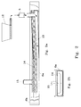
- FIG. 1 A method using two extruders (duplex extrusion) is shown in FIG.
- two pumps 12 pasty fiber composite materials are each conveyed via a pressure hose 5 into the extrusion head 13a or into the extrusion head 13b.
- the delivery rate can be set separately for each pump 12, which influences the delivery rate and delivery pressure.
- the flow path of the materials is severely broken upon entry into the extrusion heads 13a, 13b with a deflection of preferably approximately 90 °.
- the material is compressed in both extrusion heads and is given the appropriate preforms by the appropriate design of the heads at the mouth, which together are similar to the final shape of the component.
- the compression stage is designed differently depending on the component, so that laminar flow conditions of the same speed arise at the mouth even with uneven profile cross sections.
- the fiber composite material of the first extrusion head 13a is discharged and pressed into the support mold 6a, 6b by the narrowing shape of the head extension.
- the special design of the mouth in particular the head extension at the top and the inclination of the extrusion heads 13a, 13b relative to the bottom of the support mold, allow the air to escape and thus prevent it from being trapped.
- a reinforcement guide 8a can be provided, through which a continuous, oriented reinforcement material can be fed from an unwinding device via a tensioning device (not shown).
- the reinforcement material is guided over the reinforcement guide 8a to the clamping device for the reinforcement 7 and is slightly tensioned.
- the reinforcement material is fed in under constant light tension, for example unwound from spools.
- the guide between the mouths of the two extrusion heads 13a, 13b positions the reinforcement on the first extrusion layer with millimeter precision.
- the fiber composite material of the extrusion head 13b is discharged.
- the elongated upper part of the head 13b presses the second extrusion layer against the first and embeds the additional reinforcement, fabric, cord, spun threads, yarn, rovings, wire, etc. in between.
- endlessly longitudinal and / or transverse reinforced components can be manufactured with good homogeneity.
- fabric and cord allow any choice of reinforcement orientation and thus the determination of the properties depending on the component.
- the method can also be carried out with more than two extrusion heads, whereby an endless, oriented reinforcement does not necessarily have to be provided for each layer. it can also be used for the production of composite materials with or without oriented reinforcement, especially for those with at least one layer of a pasty, fibrous, cementitious building material.
- composite cross-sections from different construction or Materials are manufactured. For example, a core layer with a lower bulk density can be introduced between two cementitious layers.
- the special extrusion process of the present invention in particular the duplex extrusion, is characterized by the following special features:
- the extrusion takes place in a support mold 6a, 6b, whereby precise dimensions of the contour and a smooth, non-porous surface in the region of the support mold are achieved.
- the deformation and compression in the extrusion heads result in a compact structure and ensure good shape even with relatively dry material.
- the surface in particular also becomes denser.
- the duplex resp. Multiplex extrusion enables the reinforcement to be precisely positioned by guide 8a at the mouth between the at least two extrusion heads 13a, 13b.
- the reinforcement level is freely selectable and can therefore be precisely matched to the component and its stress.
- the drag mold 14 causes slow pressure reduction in the molded component. With slight vibration at the same time, a pore-free surface of the component on the mold side and a dimensionally stable contour on the rear of the component are achieved.
- extrusion systems according to the invention have few wearing parts and only require relatively simple extrusion tools. Therefore, you only need a small amount of maintenance and relatively inexpensive extrusion tools.
- extrusion heads 13a, 13b, etc. are preferably separable from one another, so that the “threading” of the reinforcement for the first time is simplified.
Abstract
Description
Die vorliegende Erfindung betrifft ein Verfahren für die Herstellung von Bauteilen, insbesonders von stab- oder plattenförmigen Bauteilen mit und ohne profiliertem Querschnitt aus faserverstärkten mineralisch gebundenen Baustoffen, sowie Anlagen zur Durchführung eines solchen Verfahrens. Im speziellen betrifft die vorliegende Erfindung ein Verfahren zur Herstellung von Bauteilen mit verbesserten mechanischen Eigenschaften.The present invention relates to a method for the production of components, in particular rod-shaped or plate-shaped components with and without a profiled cross section made of fiber-reinforced mineral-bound building materials, and to systems for carrying out such a method. In particular, the present invention relates to a method for producing components with improved mechanical properties.
Bauteile aus faserverstärkten zementösen Baustoffen, beispielsweise Faserbeton, Faserzement, werden nach verschiedenen Verfahren hergestellt. Für flächige und stabförmige Bauteile gelangt häufig das Giessverfahren zur Anwendung, bei welchem die vorgeschnittenen Fasern im Mischer in die Zementmatrix eingemischt werden. Der giessfähige Faserverbundwerkstoff (Matrix + Fasern) wird in Formen gefüllt und durch Vibration verdichtet. Dieses Verfahren eignet sich gut für die Herstellung von Kleinteilen mit
- beschränkten Anforderungen an die mechanischen Eigenschaften (Biegezugfestigkeit, Bruchdehnung)
- Ansprüchen an die Oberflächengestaltung (z.B. Struktur der Giessform).
- limited requirements for the mechanical properties (bending tensile strength, elongation at break)
- Demands on the surface design (eg structure of the mold).
Höhere Anforderungen bezüglich mechanischer Eigenschaften können insbesondere erfüllt werden, wenn bei gegebenem Kurzfasergehalt der Wasser/Zement-Wert gesenkt oder zusätzlich orientierte Faserbündel als Bewehrung eingebracht werden.Higher requirements with regard to mechanical properties can be met in particular if the water / cement value is reduced for a given short fiber content or if additionally oriented fiber bundles are introduced as reinforcement.
Eine Erhöhung des Kurzfasergehalts führt zu erheblichen Erschwernissen bei der Verarbeitung und hat insbesonders auch eine Erhöhung des Wasser/Zement-Wertes zur Folge. Diese Erhöhung des Wasser/Zement-Wertes wirkt sich jedoch in verschiedenen Beziehungen nachteilig auf die mechanischen Eigenschaften des Faserverbundwerkstoffes aus, wie
- Verlangsamung der Festigkeitsentwicklung
- tiefere Druck-, Zug- und Biegezugfestigkeit
- reduzierte Frostbeständigkeit
- grösseres Schwindmass und grössere feuchtigkeitsbedingte Formänderungen.
- Slowdown in strength development
- lower compressive, tensile and flexural tensile strength
- reduced frost resistance
- greater shrinkage and greater moisture-related changes in shape.
Die Verbesserung der mechanischen Eigenschaften durch Erhöhung des Fasergehaltes gelingt demzufolge nur, wenn nicht gleichzeitig der Wasser/Zement-Wert erhöht werden muss. Dies wird erreicht, wenn Matrix und Fasern nicht vorgemischt, sondern im Spritzverfahren getrennt in die Form eingebracht werden, was allerdings mit einem entsprechend grossen Aufwand verbunden und deshalb für die Serienfertigung in der Regel unwirtschaftlich ist.The mechanical properties can only be improved by increasing the fiber content if the water / cement value does not have to be increased at the same time. This is achieved when the matrix and fibers are not premixed, but are separately introduced into the mold by spraying, which, however, involves a correspondingly high outlay and is therefore generally uneconomical for series production.
Bei beiden Verfahren (Giess- und Spritzverfahren) variiert infolge der Verdichtung der Wassergehalt über den Querschnitt, was zu unterschiedlichem Schwinden über den Querschnitt führt.In both processes (pouring and spraying processes) the water content varies across the cross section due to the compression, which leads to different shrinkage across the cross section.
Aus EP 0 173 873 ist ein Verfahren bekannt, bei dem die hydraulisch abbindende Masse in einer vorgegebenen Dicke auf eine Unterlage aufgebracht wird, worauf Faserschnitzel auf die Oberfläche aufgestreut und in die Matrix eingedrückt werden. Zusätzlich können auch Endlosfasern in die Masse der herzustellenden Platte aufgelegt und/oder eingezogen werden.A method is known from EP 0 173 873 in which the hydraulically setting mass is applied to a base in a predetermined thickness, whereupon fiber chips are sprinkled onto the surface and pressed into the matrix. In addition, continuous fibers can also be placed and / or drawn into the mass of the panel to be produced.
Nachteilig bei diesem Verfahren sind die Aufeinanderfolge vieler Einzelschritte sowie die beschränkten Gestaltungsmöglichkeiten bezüglich Formgebung und Oberfläche.The disadvantage of this method is the sequence of many individual steps and the limited design options with regard to shape and surface.
Es wurde auch bereits versucht gewisse Faserverbundwerkstoffe zu extrudieren.Attempts have also already been made to extrude certain fiber composite materials.
Mit diesem Verfahren lassen sich stabförmige Bauteile mit gleichbleibendem Querschnitt äusserst rationell herstellen. Aufgrund des niedrigen Wasser/Zement-Wertes des steifplastisch verarbeitbaren Faserverbundwerkstoffes ergeben sich günstige Eigenschaften bezüglich Festigkeit, Schwinden und Quellen. Nachteilig sind das ausgesprochen spröde Bruchverhalten und die für viele Anwendungen unzureichende Oberflächenbeschaffenheit.With this process, rod-shaped components with a constant cross-section can be produced extremely efficiently. Due to the low water / cement value of the stiff plastic processable fiber composite material there are favorable properties with regard to strength, shrinkage and swelling. Disadvantages are the extremely brittle fracture behavior and the inadequate surface properties for many applications.
Ziel der vorliegenden Erfindung war es deshalb ein Verfahren zu entwickeln, welches die Vorteile des klassischen Extrusionsverfahrens mit dem des Giess- und Spritzverfahrens vereinigt, sowie Anlagen zur Durchführung dieses Verfahrens bereitzustellen. Die Vorteile des erfindungsgemässen Verfahrens sind:
- rationelle Fertigung von standardisierten profilierten und nicht profilierten Bauteilen mit stabförmiger oder flächiger Ausbildung
- gute mechanische Eigenschaften dank tiefem Wasser/Zement-Wert
- kurze Härtungszeiten
- hervorragende Oberflächengüte, entsprechend den verwendeten Formen
- gezielt in den Zonen der grössten Zugbeanspruchung angeordnete Zusatzbewehrung.
- rational production of standardized profiled and non-profiled components with rod-shaped or flat training
- good mechanical properties thanks to deep water / cement value
- short curing times
- excellent surface quality, according to the shapes used
- Additional reinforcement arranged specifically in the zones of the greatest tensile stress.
Dieses Ziel wurde erreicht durch die Bereitstellung eines Verfahrens zur Herstellung von Bauteilen, insbesondere aus faserverstärkten zementösen Baustoffen, welches dadurch gekennzeichnet ist, dass der Baustoff unter Druck in eine Stützform eingebracht wird, so dass er an jeder Stelle des Bauteils den gleichen Druckbedingungen ausgesetzt wird.This goal was achieved by providing a process for the production of components, in particular from fiber-reinforced cementitious building materials, which is characterized in that the building material is introduced into a support mold under pressure, so that it is exposed to the same pressure conditions at every point of the component.
Durch die gleichbleibenden Druckbedingungen werden Inhomogenitäten innerhalb eines Bauteils weitgehend vermieden, was zu einer Erhöhung der Festigkeit beiträgt und die Formbeständigkeit verbessert. Zudem lassen sich unter Druck steifplastischere Baustoffe verarbeiten, wodurch bei tiefem Wasser/Zement-Wert Materialien mit hohem Kurzfasergehalt verarbeitet werden können.Due to the constant pressure conditions, inhomogeneities within a component are largely avoided, which contributes to an increase in strength and improves dimensional stability. In addition, more rigid plastic materials can be processed under pressure, which means that materials with a high short fiber content can be processed when the water / cement value is low.
Vorzugsweise wird das Verfahren derart durchgeführt, dass die Strömung des frisch in die Form geleiteten Materials weitgehend laminar ist.The method is preferably carried out in such a way that the flow of the material freshly introduced into the mold is largely laminar.
Durch die gleichbleibenden Druckbedingungen sowie die vorzugsweise weitgehend laminare Strömung lassen sich auch Bewehrungen aus Endlosfasern, resp. Rovings, Cords und Gewebe, zur zusätzlichen Verbesserung der Festigkeiten und des Bruchverhaltens in das Bauteil einbauen, ohne dass Inhomogenitäten entstehen.Due to the constant pressure conditions and the preferably largely laminar flow, reinforcements made of continuous fibers, respectively. Install rovings, cords and fabric to further improve the strength and breaking behavior in the component without creating inhomogeneities.
Dieses Verfahren eignet sich insbesonders für sämtliche gefüllten z.B. faserverstärkten zementösen Baustoffe. Als Fasern können bekannte Füllmaterialien, insbesonders Faserbündel resp. aus Faserbündeln erhaltene Kurzfasern verwendet werden. Als Faserverstärkung kommen natürliche und künstliche Fasern, beispielsweise mineralische, metallische oder organische Fasern sowie Carbonfasern als Einzelfasern oder gebündelt sowohl als Kurzwie auch als Endlosfasern in Betracht. Beispiele für solche Fasermaterialien sind AR-Glasfasern, Kunststoff-Fasern, Kohlenstoff-Fasern und Stahldrähte. Diese können sowohl allein als auch in Materialkombinationen eingesetzt werden. Mögliche Vorbehandlungen der Bewehrungsmaterialien sind bekannt.This method is particularly suitable for all filled e.g. fiber-reinforced cementitious building materials. Known filling materials, in particular fiber bundles or. Short fibers obtained from fiber bundles can be used. Natural and artificial fibers, for example mineral, metallic or organic fibers as well as carbon fibers as individual fibers or bundled both as short and as continuous fibers, can be considered as fiber reinforcement. Examples of such fiber materials are AR glass fibers, plastic fibers, carbon fibers and steel wires. These can be used both alone and in combinations of materials. Possible pre-treatments of the reinforcement materials are known.
Die zementösen Baustoffe können allgemein gebräuchliche Zusätze enthalten, beispielsweise Betonverflüssiger, Hochleistungsbetonverflüssiger und Polymerdispersionen.The cementitious building materials can contain commonly used additives, for example concrete plasticizers, high-performance concrete plasticizers and polymer dispersions.
Bevorzugte Baustoffe enthalten Polymerdispersionen gewöhnlich in solchen Mengen, dass der Feststoffanteil bezüglich der ganzen Matrix 0-10 Vol % beträgt.Preferred building materials usually contain polymer dispersions in such amounts that the solids content is 0-10% by volume with respect to the entire matrix.
Der Kurzfasergehalt wird nur durch die Verarbeitbarkeit limitiert. Vorzugsweise enthalten entsprechende Mischungen aber 0,3 bis 3 Vol.-% Kurzfasern, bevorzugt 1,5 bis 2,5 Vol.-%, und weisen einen Wasser/Zement-Wert im Bereich von 0,2 bis 0,5, insbesondere 0,2 bis 0,3 auf.The short fiber content is only limited by the processability. However, corresponding mixtures preferably contain 0.3 to 3% by volume of short fibers, preferably 1.5 to 2.5% by volume, and have a water / cement value in the range from 0.2 to 0.5, in particular 0 , 2 to 0.3.
Spezielle Ausführungsarten und Anlagen zur Durchführung des Verfahrens werden anhand der Figuren näher erläutert.
Figur 1 stellt eine Vorrichtung für die Injektion über einen Kolben dar, wobei Figur 1a ein Längsschnitt und Figur 1b ein Querschnitt ist;Figur 2 zeigt eine Vorrichtung zur Herstellung eines Bauteils ohne Endlosfasern mittels Extrusion, wobei Figur 2a einen Längsschnitt und Figur 2b einen Querschnitt durch dieselbe Vorrichtung zeigt;Figur 3 zeigt einen Anlagenteil zur Herstellung eines Bauteils unter Verwendung eines Mehrfach-Extrusionskopfes, beispielsweise für die Herstellung von Produkten mit Endlosfasern als zusätzliche Bewehrung (Duplex-Extrusion), wobei Figur 3a einen Längsschnitt und Figur 3b einen Querschnitt durch denselben Anlagenteil zeigt, und- Figur 4 zeigt eine Vergrösserung des Austrittsbereichs von
Figur 3.
- FIG. 1 shows a device for injection via a piston, FIG. 1a being a longitudinal section and FIG. 1b being a cross section;
- FIG. 2 shows a device for producing a component without continuous fibers by means of extrusion, FIG. 2a showing a longitudinal section and FIG. 2b a cross section through the same device;
- FIG. 3 shows a system part for the production of a component using a multiple extrusion head, for example for the production of products with continuous fibers as additional reinforcement (duplex extrusion), FIG. 3a showing a longitudinal section and FIG. 3b a cross section through the same system part, and
- FIG. 4 shows an enlargement of the exit area from FIG. 3.
Bei der Injektion über Kolben (vgl. Figur 1) wird das gefüllte Material aus einem Druckbehälter 1, der mit einem Rührwerk 2, einem Druckbegrenzungsventil 3 und einem Steigrohr 4 versehen ist, über einen Druckschlauch 5 und das Kolbenstangenrohr 9 in einen Raum 6 eingebracht, der durch die Injektionsform 6a,6b und die Kolbenfläche 8 begrenzt wird. Durch das Einströmen des Materials wird der Kolben 8,9 innerhalb der Form 6a,6b in Gegenrichtung zum Materialfluss verschoben. Um einen Druckabfall im Raum 6 zu verhindern ist die Kolbenfläche 8 gegenüber der Injektionsform 6a mit einer Dichtung 10 abgedichtet. Selbstverständlich kann der Kolben 8,9 auch aktiv bewegt werden.In the case of injection via pistons (see FIG. 1), the filled material is introduced into a
Die in Figur 1 dargestellte Vorrichtung eignet sich auch sehr gut für die Herstellung von Bauteilen mit zusätzlicher endloser, gerichteter Bewehrung, beispielsweise mit Spinnfäden, Garn, Drähten oder Rovings (Fasersträngen). Dabei wird der Kolben mit der Bewehrung 11 in die Ausgangslage gegen die Stirne der Form 6b gefahren. Die Führungsbohrungen 8a in der Kolbenfläche 8 halten die einzelnen Bewehrungsfäden in Position.The device shown in Figure 1 is also very well suited for the production of components with additional endless, directed reinforcement, for example with spun threads, yarn, wires or rovings (fiber strands). The piston with the
Das Verankern der Bewehrung 11 erfolgt in der Stirne der Form 6b. Die dafür vorgesehenen Trennflächen 7 der Stirne resp. eine andere Befestigungsvorrichtung, klemmen resp. halten die einzelnen Fäden oder die Drähte und positionieren diese. Nach dem Verankern wird die Bewehrung leicht gespannt.The
Pressluft mit üblicherweise 2 bis 3 bar beaufschlagt den in einen Druckbehälter 1 gefüllten Faserverbundwerkstoff. Der auf die Materialoberfläche wirkende Druck fördert den Verbundwerkstoff über ein Steigrohr 4 in den Druckschlauch 5. Von dort gelangt der Werkstoff ins Kolbenstangenrohr 9 und weiter zur Mündung in den Kolbenraum 6.Compressed air usually with 2 to 3 bar acts on the fiber composite material filled in a
Das Einpressen des Faserverbundwerkstoffes in den Kolbenraum 6 schiebt den Injektionskolben 8,9 zurück. Die Kolbengegenkraft regelt den Druck im System. Der Faserverbundwerkstoff umströmt die Bewehrung 11, sobald diese die Kolbenfläche (Führung) verlässt. Dadurch ist eine millimetergenaue Positionierung der Bewehrung 11 gewährleistet.The pressing of the fiber composite material into the
Wenn sich der Kolben während des Injektionsvorgangs bewegt, führt er die Bewehrung, welche beispielsweise vorgängig von Spulen (nicht gezeigt) abwickelt und in der Stirnfläche 6b fixiert worden ist.If the piston moves during the injection process, it carries the reinforcement, which, for example, has previously been unwound from coils (not shown) and has been fixed in the
Zusätzlich kann direkt am Kolben eine leichte Vibration vorgesehen werden, um den Faserverbundwerkstoff zusätzlich zu verdichten.In addition, a slight vibration can be provided directly on the piston in order to additionally compress the fiber composite material.
Durch die Injektion in eine geschlossene Form wird eine allseitig modellglatte, hochwertige Oberfläche des Bauteils sowie gute Masshaltigkeit erzielt.The injection into a closed mold achieves a high-quality surface of the component that is smooth on all sides and good dimensional stability.
Die Injektion über Kolben bewirkt ein über den ganzen Injektionsprozess gleiches Strömungsverhalten, homogenen Materialaufbau und dadurch gleichmässiges Schwinden über das ganze Bauteil.Injection via pistons results in the same flow behavior over the entire injection process, homogeneous material build-up and thus even shrinkage over the entire component.
Das Verdichten in der Form unter Druck und gegebenenfalls leichter Vibration führt zu einem kompakten Gefüge und wenig Lufteinschluss.The compression in the mold under pressure and possibly slight vibration leads to a compact structure and little air entrapment.
Das Injektionsverfahren über Kolben ermöglicht ausserdem genaue Positionierung der Bewehrung durch Führung in der Kolbenfläche sowie präzise Anordnung der Bewehrung an jeder Stelle des Profilquerschnittes.The injection method using pistons also enables precise positioning of the reinforcement by guiding it in the piston surface and precise arrangement of the reinforcement at every point in the profile cross-section.
Die Anlage ist einfach und weist sehr wenig Verschleissteile auf, da wenig bewegte Teile vorhanden sind, zumal wenn der Kolbenvorschub durch den Injektionswerkstoff erzeugt wird. Dadurch werden
- der Unterhalt geringer, und
- die Injektionswerkzeuge sowie
- die Anlage kostengünstiger.
- maintenance less, and
- the injection tools as well
- the plant cheaper.
Durch den im Vergleich zu Giessverfahren deutlich geringeren Wasseranspruch der Mischung (tieferer Wasser/Zement-Wert) wird zudem das Schwind- und Quellmass kleiner.Due to the significantly lower water requirements of the mixture compared to the pouring process (lower water / cement value), the shrinkage and swelling dimensions are also smaller.
Ein der Injektion über Kolben ähnliches Verfahren ist der Extrusionsprozess. Für nicht zusätzlich mit Endlosfasern bewehrte Bauteile eignet sich die einfache Extrusion. Eine geeignete Anlage ist in Figur 2 dargestellt.A process similar to piston injection is the extrusion process. Simple extrusion is suitable for components that are not additionally reinforced with continuous fibers. A suitable system is shown in Figure 2.
Um die gleichmässigen Druckbedingungen im Extrusionsverfahren zu gewährleisten, wird mittels eines speziellen, sich gegen die Mündung hin verjüngenden Extrusionskopfs in eine Stützform 6a,6b extrudiert.In order to ensure the uniform pressure conditions in the extrusion process, extrusion is carried out in a
Die spezielle Gestaltung des Extrusionskopfs gestattet den Druckaufbau, was zu den günstigen Austragsbedingungen einer Vorform bei gleichzeitig zusätzlicher Verdichtung führt. Direkt nach dem Austragen erfolgt eine Nachverdichtung in der Stützform, was die Formgenauigkeit verbessert und die Oberflächenvergütung ermöglicht.The special design of the extrusion head enables pressure to be built up, which leads to the favorable discharge conditions of a preform with simultaneous additional compression. Immediately after discharge, the support mold is compressed again, which improves the shape accuracy and enables the surface finish.
Mit einer Pumpe 12 wird der pastöse Faserverbundwerkstoff über einen Druckschlauch 5 in den Extrusionskopf 13 gefördert. Der Strömungsverlauf des Faserverbundwerkstoffs wird beim Eintritt in den Extrusionskopf 13 mit einer Umlenkung von üblicherweise ca.90°stark gebrochen. Damit wird im Kopf 13 die Beeinflussung des Strömungsverhaltens durch den Förderschlauch 5 eliminiert. Der Werkstoff wird im Extrusionskopf 13, der sich auf die Mündung zu verjüngt, verdichtet und erhält durch die entsprechende Ausbildung des Kopfs an der Mündung die Vorform, welche der endgültigen Form des Bauteils ähnlich ist. Durch die Verdichtung im Extrusionskopf 13 und die verengende Form der Kopfverlängerung oben und seitlich an der Mündung des Extrusionskopfs 13 wird an der Mündung eine weitgehend laminare Strömung erzielt. Der Faserverbundwerkstoff wird ausgetragen und durch die verengende Form der Kopfverlängerung in die Stützform 6a,6b gepresst. Die spezielle Gestaltung der Mündung, insbesondere auch deren schwache Neigung gegenüber dem Boden der Stützform 6a,6b, ermöglicht das Entweichen der Luft und verhindert so deren Einschluss. Mit einer Schleppform 14, die die Kontur der Bauteilrückseite hat und vor dem Extrusionskopf resp. diesen etwas überlagernd angeordnet ist, wird der vorhandene Druck in der Austragszone langsam abgebaut. Ein kleiner Vibrator 15 auf der Schleppform 14 unterstützt den gesamten Austragungsprozess und bewirkt im Zusammenspiel mit anderen Vorgängen eine hohe Oberflächengüte des Bauteils.With a
Ein Verfahren unter Verwendung von zwei Extrudern (Duplex-Extrusion) wird in Figur 3 dargestellt. Mit zwei Pumpen 12 werden pastöse Faserverbundwerkstoffe über je einen Druckschlauch 5 in den Extrusionskopf 13a bzw. in den Extrusionskopf 13b befördert. Für jede Pumpe 12 kann die Förderleistung separat eingestellt werden, was die Fördermenge und den Förderdruck beeinflusst. Wie beim Verfahren mit nur einem Extruder wird der Strömungsverlauf der Werkstoffe beim Eintritt in die Extrusiosköpfe 13a, 13b mit einer Umlenkung von vorzugsweise ca. 90° stark gebrochen. Der Werkstoff wird in beiden Extrusionsköpfen verdichtet und erhält durch die entsprechende Ausbildung der Köpfe an der Mündung entsprechende Vorformen, welche gemeinsam der endgültigen Form des Bauteils ähnlich sind. Die Verdichtungsstufe wird je nach Bauteil unterschiedlich ausgebildet, damit auch bei ungleichmässigen Profilquerschnitten an der Mündung laminare Strömungsverhältnisse gleicher Geschwindigkeit entstehen. Der Faserverbundwerkstoff des ersten Extrusionskopfs 13a wird ausgetragen und durch die verengende Form der Kopfverlängerung in die Stützform 6a,6b gepresst. Die spezielle Gestaltung der Mündung, insbesondere die Kopfverlängerung oben und die Neigung der Extrusionsköpfe 13a,13b gegenüber dem Boden der Stützform, ermöglicht das Entweichen der Luft und verhindert so deren Einschluss. Im vorgezogenen schleppformseitigen Teil des Extrusionskopfs 13a kann eine Bewehrungsführung 8a vorgesehen sein, durch die ein kontinuierliches, orientiertes Bewehrungsmaterial von einer Abwickelvorrichtung über eine Spannvorrichtung (nicht gezeigt) zugeführt werden kann. Für die Herstellung von Bauteilen, die mit einer endlosen, gerichteten Bewehrung versehen sind, wird das Bewehrungsmaterial über die Bewehrungsführung 8a zur Klemmvorrichtung für die Bewehrung 7 geführt und leicht gespannt. Während der Produktion wird das Bewehrungsmaterial unter konstanter leichter Spannung zugeführt, beispielsweise von Spulen abgewickelt. Die Führung zwischen den Mündungen der beiden Extrusionsköpfe 13a, 13b positioniert die Bewehrung millimetergenau auf der ersten Extrusionsschicht. Der Faserverbundwerkstoff des Extrusionskopfs 13b wird ausgetragen. Der verlängerte Oberteil des Kopfes 13b presst die zweite Extrusionsschicht gegen die erste und bettet die dazwischenliegende Zusatzbewehrung, Gewebe, Cord, Spinnfäden, Garn, Rovings, Draht etc., ein. Wie bei der einfachen Extrusion wird mit einer Schleppform, welche die Kontur der Bauteilrückseite hat, der vorhandene Druck in der Austragszone langsam abgebaut. Auch hier unterstützt ein kleiner Vibrator 15 auf der Schleppform 14, den gesamten Austragungsprozess und bewirkt im Zusammenspiel mit anderen Vorgängen eine hohe Oberflächengüte des Bauteils.A method using two extruders (duplex extrusion) is shown in FIG. With two
Die genaue Ausbildung einer möglichen Anlage für die Duplex-Extrusion im Bereich des Materialaustrags aus den Extrusionsköpfen 13a,13b in die Stützform 6a,6b wird in Figur 4 gezeigt. Wichtig für die Erzielung der gewünschten Eigenschaften ist, dass die Formgebung unter Druck geschieht. Dies kann dadurch bewirkt werden, dass der Extrusionskopf 13a,13b oben, d.h. schleppformsseitig verlängert ist. Die genaue Ausbildung ist sowohl material- als auch bauteilabhängig.The exact design of a possible system for duplex extrusion in the area of material discharge from the extrusion heads 13a, 13b into the
Mittels dieses Duplex-Extrusionsverfahrens können endlos längs- und/oder querbewehrte Bauteile mit guter Homogenität hergestellt werden. Insbesondere Gewebe und Cord ermöglichen die beliebige Wahl der Bewehrungsausrichtung und damit die Bestimmung der Eigenschaften je nach Bauteil.Using this duplex extrusion process, endlessly longitudinal and / or transverse reinforced components can be manufactured with good homogeneity. In particular, fabric and cord allow any choice of reinforcement orientation and thus the determination of the properties depending on the component.
Das Verfahren kann selbstverständlich auch mit mehr als zwei Extrusionsköpfen durchgeführt werden, wobei nicht unbedingt bei jeder Schicht eine endlose, orientierte Bewehrung vorgesehen werden muss, resp. kann es auch zur Herstellung von Verbundwerkstoffen mit oder ohne orientierte Bewehrung verwendet werden, insbesondere für solche, mit mindestens einer Schicht aus einem pastösen, faserhaltigen, zementösen Baustoff. Mit beispielsweise mind. zwei Extrudern können Verbundquerschnitte aus unterschiedlichen Bau- resp. Werkstoffen hergestellt werden. Beispielsweise kann zwischen zwei zementösen Schichten eine Kernschicht mit geringerer Rohdichte eingebracht werden.Of course, the method can also be carried out with more than two extrusion heads, whereby an endless, oriented reinforcement does not necessarily have to be provided for each layer. it can also be used for the production of composite materials with or without oriented reinforcement, especially for those with at least one layer of a pasty, fibrous, cementitious building material. With at least two extruders, for example, composite cross-sections from different construction or Materials are manufactured. For example, a core layer with a lower bulk density can be introduced between two cementitious layers.
Das spezielle Extrusionsverfahren der vorliegenden Erfindung, insbesonders die Duplex-Extrusion, wird durch die folgenden speziellen Merkmale gekennzeichnet: Die Extrusion erfolgt in eine Stützform 6a,6b, wodurch genaue Abmessungen der Kontur sowie eine glatte, porenfreie Oberfläche im Bereich der Stützform erzielt wird.The special extrusion process of the present invention, in particular the duplex extrusion, is characterized by the following special features: The extrusion takes place in a
Dank der Möglichkeit Faserverbundwerkstoffe mit kleinstmöglichem Wassergehalt zu verarbeiten, werden gute Festigkeitswerte, kleines Schwinden, gute Formstabilität im frischen Zustand, homogener Materialaufbau über den gesamten Profilquerschnitt und gleichmässiges Schwinden über den ganzen Querschnitt erzielt.Thanks to the possibility of processing fiber composite materials with the lowest possible water content, good strength values, small shrinkage, good dimensional stability in the fresh state, homogeneous material structure over the entire profile cross section and uniform shrinkage over the entire cross section are achieved.
Die Verformung und die Verdichtung in den Extrusionsköpfen führen zu einem kompakten Gefüge und gewährleisten gute Formgebung auch bei relativ trockenem Werkstoff.The deformation and compression in the extrusion heads result in a compact structure and ensure good shape even with relatively dry material.
Infolge des zweiten Druckaufbaus in der Stützform 6a,6b wird insbesondere auch die Oberfläche dichter.As a result of the second pressure build-up in the
Durch die spezielle Ausbildung der Extrusionsköpfe 13a,13b im Bereich der Mündung sowie die Neigung der Köpfe, kann die Luft gut entweichen, wodurch Lufteinschluss weitgehend vermieden werden kann.Due to the special design of the extrusion heads 13a, 13b in the region of the mouth and the inclination of the heads, the air can escape well, as a result of which air inclusion can be largely avoided.
Die Duplex- resp. Multiplex-Extrusion ermöglicht die genaue Positionierung der Bewehrung durch Führung 8a an der Mündung zwischen den mindestens zwei Extrusionsköpfen 13a,13b. Die Bewehrungsebene ist frei wählbar und kann damit genau auf das Bauteil und dessen Beanspruchung abgestimmt werden.The duplex resp. Multiplex extrusion enables the reinforcement to be precisely positioned by
Durch die Schleppform 14 wird ein langsamer Druckabbau im geformten Bauteil bewirkt. Bei gleichzeitiger leichter Vibration wird eine porenfreie Oberfläche des Bauteils auf der Formseite sowie eine masshaltige Kontur auf der Bauteilrückseite bewirkt.The
Die erfindungsgemässen Extrusionsanlagen weisen wenig Verschleissteile auf und benötigen nur relativ einfache Extrusionswerkzeuge. Deshalb brauchen Sie nur geringen Unterhalt sowie relativ kostengünstige Extrusionswerkzeuge.The extrusion systems according to the invention have few wearing parts and only require relatively simple extrusion tools. Therefore, you only need a small amount of maintenance and relatively inexpensive extrusion tools.
Vorzugsweise sind die Extrusionsköpfe 13a, 13b etc. voneinander trennbar, damit das erstmalige "Einfädeln" der Bewehrung vereinfacht wird.The extrusion heads 13a, 13b, etc. are preferably separable from one another, so that the “threading” of the reinforcement for the first time is simplified.
Spezielle Ausführungsarten der hier dargelegten Erfindung werden in den abhängigen Ansprüchen näher beschrieben.Special embodiments of the invention presented here are described in more detail in the dependent claims.
Claims (18)
Applications Claiming Priority (2)
| Application Number | Priority Date | Filing Date | Title |
|---|---|---|---|
| CH365493A CH688033A5 (en) | 1993-12-08 | 1993-12-08 | A method for the production of components of building materials faserverstaerkten mineral-bound. |
| CH3654/93 | 1993-12-08 |
Publications (1)
| Publication Number | Publication Date |
|---|---|
| EP0657258A1 true EP0657258A1 (en) | 1995-06-14 |
Family
ID=4260663
Family Applications (1)
| Application Number | Title | Priority Date | Filing Date |
|---|---|---|---|
| EP94118641A Withdrawn EP0657258A1 (en) | 1993-12-08 | 1994-11-26 | Process for making building elements, in particular from fibre reinforced mineral materials |
Country Status (2)
| Country | Link |
|---|---|
| EP (1) | EP0657258A1 (en) |
| CH (1) | CH688033A5 (en) |
Cited By (2)
| Publication number | Priority date | Publication date | Assignee | Title |
|---|---|---|---|---|
| DE19654564A1 (en) * | 1996-12-27 | 1998-07-02 | Fertig Decken Union Gmbh | Fibre reinforced concrete construction element manufactured by casting |
| DE10037766A1 (en) * | 2000-08-03 | 2002-02-14 | Hochtief Fertigteilbau Gmbh | Prestressed concrete hollow slab and method for producing the same |
Citations (14)
| Publication number | Priority date | Publication date | Assignee | Title |
|---|---|---|---|---|
| GB184555A (en) * | 1921-05-10 | 1922-08-10 | William Sykes | Improvements in or relating to the manufacture of lengthy articles of plastic material, with special reference to reinforced concrete |
| DE1121523B (en) * | 1959-02-25 | 1962-01-04 | Gustav Hoke Dr Ing | Method and device for producing bodies from concrete, fiber cement and the like. like vented masses |
| FR1293755A (en) * | 1961-05-26 | 1962-05-18 | Eternit Sa | Method and device for manufacturing, in a mold, a body from an aqueous and fibrous mixture |
| US3146508A (en) * | 1959-11-03 | 1964-09-01 | Henry A Berliner | Apparatus for extruding reinforced members |
| GB1143514A (en) * | 1966-06-02 | 1969-02-26 | Uralita Sa | Moulds for the manufacture of asbestos-cement products |
| GB1277309A (en) * | 1969-09-22 | 1972-06-14 | Oscar Lee Reed | Post forming machine |
| DE2734483A1 (en) * | 1977-07-30 | 1979-02-08 | Norbert Colberg | Panels, extrudates, mouldings used in building or civil engineering - are mfd. from cement-bonded fibres or chips with metal or nylon netting as reinforcement |
| JPS6186209A (en) * | 1984-10-03 | 1986-05-01 | 株式会社クボタ | Manufacture of inorganic board material |
| JPH01103943A (en) * | 1987-10-15 | 1989-04-21 | Kubota Ltd | Method for extrusion molding inorganic product |
| DE3903640A1 (en) * | 1988-02-09 | 1989-08-17 | N Proizv Ob Energostroiprom | Process and installation for producing hollow bodies from building material mixtures, preferably concrete mixtures |
| EP0347092A2 (en) * | 1988-06-11 | 1989-12-20 | Redland Roof Tiles Limited | Process for the production of concrete building products |
| JPH0269368A (en) * | 1988-09-02 | 1990-03-08 | Kubota Ltd | Extrusion molding method of inorganic product |
| WO1993020990A1 (en) * | 1992-04-14 | 1993-10-28 | Assadollah Redjvani | A method of continuous concrete casting by extrusion |
| DE4218710C1 (en) * | 1992-06-06 | 1993-11-18 | Hochtief Ag Hoch Tiefbauten | Tubbing-production equipment for tunnel-lining - uses fully-enclosed shell mould with two unions in bottom for concrete pumped from mixer |
-
1993
- 1993-12-08 CH CH365493A patent/CH688033A5/en not_active IP Right Cessation
-
1994
- 1994-11-26 EP EP94118641A patent/EP0657258A1/en not_active Withdrawn
Patent Citations (14)
| Publication number | Priority date | Publication date | Assignee | Title |
|---|---|---|---|---|
| GB184555A (en) * | 1921-05-10 | 1922-08-10 | William Sykes | Improvements in or relating to the manufacture of lengthy articles of plastic material, with special reference to reinforced concrete |
| DE1121523B (en) * | 1959-02-25 | 1962-01-04 | Gustav Hoke Dr Ing | Method and device for producing bodies from concrete, fiber cement and the like. like vented masses |
| US3146508A (en) * | 1959-11-03 | 1964-09-01 | Henry A Berliner | Apparatus for extruding reinforced members |
| FR1293755A (en) * | 1961-05-26 | 1962-05-18 | Eternit Sa | Method and device for manufacturing, in a mold, a body from an aqueous and fibrous mixture |
| GB1143514A (en) * | 1966-06-02 | 1969-02-26 | Uralita Sa | Moulds for the manufacture of asbestos-cement products |
| GB1277309A (en) * | 1969-09-22 | 1972-06-14 | Oscar Lee Reed | Post forming machine |
| DE2734483A1 (en) * | 1977-07-30 | 1979-02-08 | Norbert Colberg | Panels, extrudates, mouldings used in building or civil engineering - are mfd. from cement-bonded fibres or chips with metal or nylon netting as reinforcement |
| JPS6186209A (en) * | 1984-10-03 | 1986-05-01 | 株式会社クボタ | Manufacture of inorganic board material |
| JPH01103943A (en) * | 1987-10-15 | 1989-04-21 | Kubota Ltd | Method for extrusion molding inorganic product |
| DE3903640A1 (en) * | 1988-02-09 | 1989-08-17 | N Proizv Ob Energostroiprom | Process and installation for producing hollow bodies from building material mixtures, preferably concrete mixtures |
| EP0347092A2 (en) * | 1988-06-11 | 1989-12-20 | Redland Roof Tiles Limited | Process for the production of concrete building products |
| JPH0269368A (en) * | 1988-09-02 | 1990-03-08 | Kubota Ltd | Extrusion molding method of inorganic product |
| WO1993020990A1 (en) * | 1992-04-14 | 1993-10-28 | Assadollah Redjvani | A method of continuous concrete casting by extrusion |
| DE4218710C1 (en) * | 1992-06-06 | 1993-11-18 | Hochtief Ag Hoch Tiefbauten | Tubbing-production equipment for tunnel-lining - uses fully-enclosed shell mould with two unions in bottom for concrete pumped from mixer |
Non-Patent Citations (3)
| Title |
|---|
| DATABASE WPI Week 8624, Derwent World Patents Index; AN 86-152871 * |
| PATENT ABSTRACTS OF JAPAN vol. 13, no. 326 (C - 620) 24 July 1989 (1989-07-24) * |
| PATENT ABSTRACTS OF JAPAN vol. 14, no. 250 (C - 0723) 29 May 1990 (1990-05-29) * |
Cited By (3)
| Publication number | Priority date | Publication date | Assignee | Title |
|---|---|---|---|---|
| DE19654564A1 (en) * | 1996-12-27 | 1998-07-02 | Fertig Decken Union Gmbh | Fibre reinforced concrete construction element manufactured by casting |
| DE19654564C2 (en) * | 1996-12-27 | 2000-01-20 | Fertig Decken Union Gmbh | Casting process suitable for the plant and construction site for the manufacture of a large-format component reinforced by fibers with a relatively large thickness made of concrete |
| DE10037766A1 (en) * | 2000-08-03 | 2002-02-14 | Hochtief Fertigteilbau Gmbh | Prestressed concrete hollow slab and method for producing the same |
Also Published As
| Publication number | Publication date |
|---|---|
| CH688033A5 (en) | 1997-04-30 |
Similar Documents
| Publication | Publication Date | Title |
|---|---|---|
| EP0710313B1 (en) | Anchorage device for high-performance fiber composite cables | |
| EP0771259B1 (en) | Device for manufacturing plastic parts with incorporated reinforcement fibres | |
| EP0579047B1 (en) | Method for production of fiber reinforced semi-finished products of medium to high viscosity thermoplastics | |
| EP0149195B1 (en) | Structural foam with an integral skin and method for producing it | |
| WO1990006218A1 (en) | Preform made from injection moulded or extruded plastic waste materials | |
| DE19930920A1 (en) | Long fiber reinforced thermoplastic material and method of making the same | |
| EP0158118A2 (en) | Method and apparatus for producing composite sections | |
| EP0364828B1 (en) | Extrusion impregnation apparatus | |
| DE4302409C2 (en) | Tension or rock anchors with molded thread and method for producing the same | |
| EP0026795B1 (en) | Profiled building strip, especially a profile strip for the manufacture of window frames, and process for its manufacture | |
| EP0151930B1 (en) | Method of manufacturing a tubular element and compound tube obtained by said method | |
| DE19625426A1 (en) | High strength composite connector, connector use | |
| DE3438448C2 (en) | ||
| EP0657258A1 (en) | Process for making building elements, in particular from fibre reinforced mineral materials | |
| DE3839835A1 (en) | Threaded rods and bolts of thermoplastic materials reinforced with continuous and chopped strands | |
| DE1440200B2 (en) | CONNECTING ELEMENT FOR HANGING INSULATORS OF THE CAP AND LOCKING TYPE IN AN ISOLATOR CHAIN AND A PROCESS FOR MANUFACTURING SUCH CONNECTING ELEMENTS | |
| DE2500375A1 (en) | Screw-threaded polyester rod reinforced with glass fibres - produced by moulding or twisting without cutting glass fibres | |
| EP0185960B1 (en) | Production of reinforced plastics | |
| EP3141362B1 (en) | Method for producing a structure made of mortar or concrete and device for the same | |
| EP3705250B1 (en) | Method for producing a concrete component and concrete part producing device | |
| EP1623807B2 (en) | Method and device for producing a wood-based object | |
| DE2903019A1 (en) | METHOD AND DEVICE FOR THE PRODUCTION OF TUBULAR HOLLOW BODIES AND THE USE THEREOF | |
| DE1504036A1 (en) | Process for the production of workpieces made of plastics with at least longitudinal reinforcement inserts | |
| CH669361A5 (en) | ||
| DE10063461A1 (en) | Shaped part made of a formable building material, in particular as lost formwork, and method and device for producing the same |
Legal Events
| Date | Code | Title | Description |
|---|---|---|---|
| PUAI | Public reference made under article 153(3) epc to a published international application that has entered the european phase |
Free format text: ORIGINAL CODE: 0009012 |
|
| AK | Designated contracting states |
Kind code of ref document: A1 Designated state(s): AT BE CH DE FR IT LI NL |
|
| 17P | Request for examination filed |
Effective date: 19951201 |
|
| 17Q | First examination report despatched |
Effective date: 19980423 |
|
| STAA | Information on the status of an ep patent application or granted ep patent |
Free format text: STATUS: THE APPLICATION IS DEEMED TO BE WITHDRAWN |
|
| 18D | Application deemed to be withdrawn |
Effective date: 20000418 |