EP0656986B1 - Insert for use in slips - Google Patents
Insert for use in slips Download PDFInfo
- Publication number
- EP0656986B1 EP0656986B1 EP93919255A EP93919255A EP0656986B1 EP 0656986 B1 EP0656986 B1 EP 0656986B1 EP 93919255 A EP93919255 A EP 93919255A EP 93919255 A EP93919255 A EP 93919255A EP 0656986 B1 EP0656986 B1 EP 0656986B1
- Authority
- EP
- European Patent Office
- Prior art keywords
- insert
- teeth
- strips
- casing
- slips
- Prior art date
- Legal status (The legal status is an assumption and is not a legal conclusion. Google has not performed a legal analysis and makes no representation as to the accuracy of the status listed.)
- Expired - Lifetime
Links
Images

Classifications
-
- B—PERFORMING OPERATIONS; TRANSPORTING
- B25—HAND TOOLS; PORTABLE POWER-DRIVEN TOOLS; MANIPULATORS
- B25B—TOOLS OR BENCH DEVICES NOT OTHERWISE PROVIDED FOR, FOR FASTENING, CONNECTING, DISENGAGING, OR HOLDING
- B25B1/00—Vices
- B25B1/24—Details, e.g. jaws of special shape, slideways
- B25B1/2405—Construction of the jaws
- B25B1/241—Construction of the jaws characterised by surface features or material
-
- E—FIXED CONSTRUCTIONS
- E21—EARTH OR ROCK DRILLING; MINING
- E21B—EARTH OR ROCK DRILLING; OBTAINING OIL, GAS, WATER, SOLUBLE OR MELTABLE MATERIALS OR A SLURRY OF MINERALS FROM WELLS
- E21B19/00—Handling rods, casings, tubes or the like outside the borehole, e.g. in the derrick; Apparatus for feeding the rods or cables
- E21B19/02—Rod or cable suspensions
- E21B19/06—Elevators, i.e. rod- or tube-gripping devices
- E21B19/07—Slip-type elevators
-
- F—MECHANICAL ENGINEERING; LIGHTING; HEATING; WEAPONS; BLASTING
- F16—ENGINEERING ELEMENTS AND UNITS; GENERAL MEASURES FOR PRODUCING AND MAINTAINING EFFECTIVE FUNCTIONING OF MACHINES OR INSTALLATIONS; THERMAL INSULATION IN GENERAL
- F16L—PIPES; JOINTS OR FITTINGS FOR PIPES; SUPPORTS FOR PIPES, CABLES OR PROTECTIVE TUBING; MEANS FOR THERMAL INSULATION IN GENERAL
- F16L3/00—Supports for pipes, cables or protective tubing, e.g. hangers, holders, clamps, cleats, clips, brackets
- F16L3/08—Supports for pipes, cables or protective tubing, e.g. hangers, holders, clamps, cleats, clips, brackets substantially surrounding the pipe, cable or protective tubing
- F16L3/10—Supports for pipes, cables or protective tubing, e.g. hangers, holders, clamps, cleats, clips, brackets substantially surrounding the pipe, cable or protective tubing divided, i.e. with two members engaging the pipe, cable or protective tubing
-
- Y—GENERAL TAGGING OF NEW TECHNOLOGICAL DEVELOPMENTS; GENERAL TAGGING OF CROSS-SECTIONAL TECHNOLOGIES SPANNING OVER SEVERAL SECTIONS OF THE IPC; TECHNICAL SUBJECTS COVERED BY FORMER USPC CROSS-REFERENCE ART COLLECTIONS [XRACs] AND DIGESTS
- Y10—TECHNICAL SUBJECTS COVERED BY FORMER USPC
- Y10S—TECHNICAL SUBJECTS COVERED BY FORMER USPC CROSS-REFERENCE ART COLLECTIONS [XRACs] AND DIGESTS
- Y10S294/00—Handling: hand and hoist-line implements
- Y10S294/902—Gripping element
Definitions
- This invention relates to an insert for use in slips, an adaptor provided with a plurality of such inserts and slips provided with one or more such adaptors.
- the invention also relates to an elevator provided with inserts in accordance with the invention.
- Slips are used to hold casing in position whilst additional lengths of casing are being added to the casing string.
- WO-A-91 18181 discloses an insert for use in slips, which insert comprises a resilient base member in which are embedded a plurality of pipe gripping members.
- the pipe gripping members disclosed are pins which significantly enhance the gripping properties of the insert whilst causing minimal damage to the surface of the pipe to be gripped.
- US-A-2 493 556 discloses an insert for use in slips, which insert comprises a plurality of strips which are embedded side by side in a resilient base member and each of which has a pipe gripping edge.
- the resilient base member projects beyond the strips so that when the insert is applied to casing the resilient base member is in continuous contact with the casing and forms a fluid tight seal therewith.
- US-A-2 830 788 discloses an apparatus for raising and lowering the deck of a drilling barge on caissons. During the raising and lowering operations the deck is supported temporarily by applying a plurality of segmented metal shoes to the outer surface of the caissons.
- the segmented metal shoes are mounted on the inner periphery of resilient rings which are disposed circumjacent the respective caissons.
- the segmented metal shoes are urged against the caissons by the application of fluid pressure to the resilient rings.
- Each segmented metal shoe covers a significant portion of the circumference of its respective caisson.
- the present invention aims, at least in its preferred embodiments, to provide an insert which will adequately grip reasonably long casing strings with minimal damage to the casing.
- an insert for use in slips which insert comprises a plurality of strips which are embedded side by side in a resilient base member and each of which has a pipe gripping edge, characterised in that said strips project beyond said resilient base member to form channels between adjacent strips to accommodate debris from the surface of the casing to be gripped.
- This arrangement allows space between the strips to accommodate paint and other debris derived from the surface of the casing.
- said pipe gripping edge comprises teeth.
- it could also comprise particulate material bonded to said strips.
- Such material could comprise, for example carborundum or diamond grit.
- said teeth have a leading face which is inclined at an angle ⁇ of from 60° to 120° to the longitudinal axis of the strip.
- ⁇ is substantially 90°.
- said teeth have a trailing face which is inclined at an angle ⁇ of from 20° to 50° to the longitudinal axis of the strip.
- ⁇ is substantially 35°.
- the depth (d) of said teeth is from 0.2mm to 2mm.
- d is substantially 1mm.
- the teeth may be of differing hardness, for example relatively hard teeth towards the top of the insert and relatively soft teeth towards the bottom.
- said strips in use, extend substantially parallel with the longitudinal axis of casing to be gripped. If desired, said strip could be inclined to the longitudinal axis of the casing. In an alternative embodiment, the strips would be arranged perpendicular to the longitudinal axis of the casing to be gripped. Such an embodiment could be used where resistance to torsional forces is particularly important.
- said pipe gripping surface is covered with a material which is corrosion-resistant, for example titanium.
- the present invention also provides an adaptor provided with a plurality of inserts in accordance with the invention.
- each insert may have teeth of a specific hardness, with the hardness of the teeth of one insert differing from the hardness of the teeth of another insert.
- slips provided with one or more adaptors in accordance with the present invention.
- the present invention also provides an elevator incorporating an insert in accordance with the present invention.
- the insert 1 comprises a resilient base member 2 which is provided with a multiplicity of strips 3 which are embedded side by side in said resilient base member and an edge of each of which is provided with a plurality of teeth 4. It will be noted that the strips 3 project beyond the resilient base member 2 to form channels between adjacent strips 3.
- the resilient base member 2 is made from rubber and the strips 3 are vulcanized in position as shown.
- the teeth 4 have the shape shown in Figure 2.
- the teeth have a leading face 13 which is inclined at an angle ⁇ of 90° to the vertical X-X and a trailing face 14 which is inclined at an angle ⁇ of 35° to the vertical X-X.
- the strip 3 typically has a width W of 9mm and a length of 60mm.
- the teeth have a depth d of 1mm.
- the top rear surface of the strip 3 is provided with a chamfer 15 which enables the strips 3 to be correctly orientated during fabrication of the insert.
- the strips 3 are coated with titanium to inhibit corrosion and improve wear properties.
- an adaptor 5 which comprises an arcuate outer member 6 provided with a plurality of ribs 7 bounded by members 8.
- the arcuate outer member 6, ribs 7 and members 8 define six separate cavities 9.
- the construction of the adaptor 5 increases overall rigidity and resists twisting.
- the adaptor 5 is provided with tongues 10 which slidably engage in dove-tail grooves 11 in a wedge 12.
- a plurality of adaptors 5, typically three, are arranged in a circle in an apparatus (generally referred to as "slips") for holding a casing string.
- an apparatus generally referred to as "slips" for holding a casing string.
- wedges 12 are lowered into a tapered base member (not shown). This applies the teeth to the side of the casing. As the casing is lowered the teeth grip the casing and urge the wedges 12 downwardly further gripping the casing.
- the channels between adjacent strips 3 accommodate debris from the surface of the casing.
- the teeth 3 of an insert could be of different hardnesses, for example relatively hard (and brittle) teeth at the top of the insert and softer (and less brittle) teeth at the bottom of the insert. Harder teeth are better for gripping the pipe, however, if the hard teeth are snapped off the softer teeth will still grip the pipe, albeit at the cost of some surface damage.
- the teeth of the inserts in an adaptor may have differing hardness with, for example the hardness of the teeth in the uppermost insert being greater than the hardness in the lowermost insert.
- the teeth 4 could be formed by covering the strips 3 with a coating of abrasive material, for example carborundum or diamond dust.
- the teeth shown in Figure 2 are preferred since they help apply the slips when the casing is lowered and are comparatively easy to release when the casing is raised prior to releasing the slips.
- inserts in accordance with the present invention may also be incorporated in elevators for moving individual pipes and short pipe strings.
- the strips used in inserts for elevators may have less pointed teeth, for example as shown in Figure 4 or Figure 5.
- the tips of the teeth are quite rounded whilst in Figure 5 the tip of each tooth is provided with a flat having a length of, for example 0.25mm.
Landscapes
- Engineering & Computer Science (AREA)
- Mechanical Engineering (AREA)
- Geology (AREA)
- General Engineering & Computer Science (AREA)
- Life Sciences & Earth Sciences (AREA)
- Mining & Mineral Resources (AREA)
- General Life Sciences & Earth Sciences (AREA)
- Fluid Mechanics (AREA)
- Environmental & Geological Engineering (AREA)
- Geochemistry & Mineralogy (AREA)
- Physics & Mathematics (AREA)
- Mutual Connection Of Rods And Tubes (AREA)
- Hand Tools For Fitting Together And Separating, Or Other Hand Tools (AREA)
- Earth Drilling (AREA)
- Load-Engaging Elements For Cranes (AREA)
- Golf Clubs (AREA)
- Manipulator (AREA)
Abstract
Description
- This invention relates to an insert for use in slips, an adaptor provided with a plurality of such inserts and slips provided with one or more such adaptors. The invention also relates to an elevator provided with inserts in accordance with the invention.
- Slips are used to hold casing in position whilst additional lengths of casing are being added to the casing string.
- Applicants WO-A-91 18181 discloses an insert for use in slips, which insert comprises a resilient base member in which are embedded a plurality of pipe gripping members. The pipe gripping members disclosed are pins which significantly enhance the gripping properties of the insert whilst causing minimal damage to the surface of the pipe to be gripped.
- US-A-2 493 556 discloses an insert for use in slips, which insert comprises a plurality of strips which are embedded side by side in a resilient base member and each of which has a pipe gripping edge. The resilient base member projects beyond the strips so that when the insert is applied to casing the resilient base member is in continuous contact with the casing and forms a fluid tight seal therewith.
- US-A-2 830 788 discloses an apparatus for raising and lowering the deck of a drilling barge on caissons. During the raising and lowering operations the deck is supported temporarily by applying a plurality of segmented metal shoes to the outer surface of the caissons. The segmented metal shoes are mounted on the inner periphery of resilient rings which are disposed circumjacent the respective caissons. The segmented metal shoes are urged against the caissons by the application of fluid pressure to the resilient rings. Each segmented metal shoe covers a significant portion of the circumference of its respective caisson.
- The present invention aims, at least in its preferred embodiments, to provide an insert which will adequately grip reasonably long casing strings with minimal damage to the casing.
- According to the present invention there is provided an insert for use in slips, which insert comprises a plurality of strips which are embedded side by side in a resilient base member and each of which has a pipe gripping edge, characterised in that said strips project beyond said resilient base member to form channels between adjacent strips to accommodate debris from the surface of the casing to be gripped.
- This arrangement allows space between the strips to accommodate paint and other debris derived from the surface of the casing.
- Preferably, said pipe gripping edge comprises teeth. However, it could also comprise particulate material bonded to said strips. Such material could comprise, for example carborundum or diamond grit.
- Advantageously, said teeth have a leading face which is inclined at an angle α of from 60° to 120° to the longitudinal axis of the strip.
- Preferably, α is substantially 90°.
- Advantageously, said teeth have a trailing face which is inclined at an angle β of from 20° to 50° to the longitudinal axis of the strip.
- Preferably β is substantially 35°.
- Advantageously, the depth (d) of said teeth is from 0.2mm to 2mm.
- Preferably, d is substantially 1mm.
- If desired, the teeth may be of differing hardness, for example relatively hard teeth towards the top of the insert and relatively soft teeth towards the bottom.
- Advantageously, said strips, in use, extend substantially parallel with the longitudinal axis of casing to be gripped. If desired, said strip could be inclined to the longitudinal axis of the casing. In an alternative embodiment, the strips would be arranged perpendicular to the longitudinal axis of the casing to be gripped. Such an embodiment could be used where resistance to torsional forces is particularly important.
- Preferably, said pipe gripping surface is covered with a material which is corrosion-resistant, for example titanium.
- The present invention also provides an adaptor provided with a plurality of inserts in accordance with the invention.
- If desired, each insert may have teeth of a specific hardness, with the hardness of the teeth of one insert differing from the hardness of the teeth of another insert.
- There is also provided slips provided with one or more adaptors in accordance with the present invention.
- The present invention also provides an elevator incorporating an insert in accordance with the present invention.
- For a better understanding of the present invention and to show how the same may be carried into effect, reference will now be made, by way of example, to the accompanying drawings, in which:-
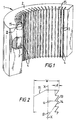
- Fig. 1 is a perspective view, with part cut away, of an insert in accordance with the invention;
- Fig. 2 is an enlarged view of the strip encircled and identified by reference numeral II in Figure 1;
- Fig. 3 is an exploded perspective view of part of a slip using inserts in accordance with the invention;
- Fig. 4 is a side view of an alternative strip; and
- Fig. 5 is a side view of a further alternative strip.
- Referring to Figure 1 of the drawings, there is shown an insert which is generally identified by reference numeral 1. The insert 1 comprises a
resilient base member 2 which is provided with a multiplicity of strips 3 which are embedded side by side in said resilient base member and an edge of each of which is provided with a plurality of teeth 4. It will be noted that the strips 3 project beyond theresilient base member 2 to form channels between adjacent strips 3. - The
resilient base member 2 is made from rubber and the strips 3 are vulcanized in position as shown. - The teeth 4 have the shape shown in Figure 2.
- In particular, the teeth have a leading
face 13 which is inclined at an angle α of 90° to the vertical X-X and atrailing face 14 which is inclined at an angle β of 35° to the vertical X-X. The strip 3 typically has a width W of 9mm and a length of 60mm. The teeth have a depth d of 1mm. In addition the top rear surface of the strip 3 is provided with achamfer 15 which enables the strips 3 to be correctly orientated during fabrication of the insert. The strips 3 are coated with titanium to inhibit corrosion and improve wear properties. - Referring now to Figure 3, there is shown an
adaptor 5 which comprises an arcuate outer member 6 provided with a plurality of ribs 7 bounded by members 8. The arcuate outer member 6, ribs 7 and members 8 define sixseparate cavities 9. The construction of theadaptor 5 increases overall rigidity and resists twisting. - The
adaptor 5 is provided withtongues 10 which slidably engage in dove-tail grooves 11 in awedge 12. - In use, a plurality of
adaptors 5, typically three, are arranged in a circle in an apparatus (generally referred to as "slips") for holding a casing string. When it is desired to hold a casing in the slips,wedges 12 are lowered into a tapered base member (not shown). This applies the teeth to the side of the casing. As the casing is lowered the teeth grip the casing and urge thewedges 12 downwardly further gripping the casing. - The channels between adjacent strips 3 accommodate debris from the surface of the casing.
- The use of multiple inserts 1 supported by respective ribs 7 reduces the overall compression in the longitudinal plane of the inserts 1 compared with an embodiment in which a single insert spans the entire depth of the
adaptor 5. - Various modifications to the embodiment described are envisaged, for example the teeth 3 of an insert could be of different hardnesses, for example relatively hard (and brittle) teeth at the top of the insert and softer (and less brittle) teeth at the bottom of the insert. Harder teeth are better for gripping the pipe, however, if the hard teeth are snapped off the softer teeth will still grip the pipe, albeit at the cost of some surface damage. If desired, the teeth of the inserts in an adaptor may have differing hardness with, for example the hardness of the teeth in the uppermost insert being greater than the hardness in the lowermost insert. In a more radical departure, the teeth 4 could be formed by covering the strips 3 with a coating of abrasive material, for example carborundum or diamond dust. However, the teeth shown in Figure 2 are preferred since they help apply the slips when the casing is lowered and are comparatively easy to release when the casing is raised prior to releasing the slips.
- Whilst primarily intended for use in slips, inserts in accordance with the present invention may also be incorporated in elevators for moving individual pipes and short pipe strings.
- The strips used in inserts for elevators (or light duty slips) may have less pointed teeth, for example as shown in Figure 4 or Figure 5. Thus, in Figure 4, the tips of the teeth are quite rounded whilst in Figure 5 the tip of each tooth is provided with a flat having a length of, for example 0.25mm.
Claims (16)
- An insert for use in slips, which insert (1) comprises a plurality of strips (3) which are embedded side by side in a resilient base member (2) and each of which has a pipe gripping edge (4), characterised in that said strips (3) project beyond said resilient base member (2) to form channels between adjacent strips (3) to accommodate debris from the surface of the casing to be gripped.
- An insert as claimed in Claim 1, wherein said pipe gripping edge (4) comprises teeth (4).
- An insert as claimed in Claim 2, wherein said teeth (4) have a leading face which is inclined at an angle (α) of from 60° to 120° to the longitudinal axis (X-X) of the strip (3).
- An insert as claimed in Claim 3, wherein α is substantially 90°.
- An insert as claimed in Claim 2, 3 or 4, wherein said teeth (4) have a trailing face which is inclined at an angle (β) of from 20° to 50° to the longitudinal axis (X-X) of the strip (3).
- An insert as claimed in Claim 5, wherein β is substantially 35°.
- An insert as claimed in any of Claims 2 to 6, wherein the depth (d) of said teeth (4) is from 0.2mm to 2mm.
- An insert as claimed in Claim 7, wherein d is substantially 1mm.
- An insert as claimed in any of Claims 2 to 8, wherein said teeth are of differing hardness.
- An insert as claimed in any preceding Claim, wherein said strips (3), in use, extend substantially parallel with the longitudinal axis of casing to be gripped.
- An insert as claimed in any preceding Claim, wherein said pipe gripping surface is covered with a material which is corrosion-resistant.
- An insert as claimed in Claim 11, wherein said material comprises titanium.
- An adaptor provided with a plurality of inserts as claimed in any preceding Claim.
- An adaptor as claimed in Claim 13, wherein each insert has teeth of a specific hardness and the hardness of the teeth of one insert differs from the hardness of the teeth of another insert.
- Slips provided with one or more adaptors as claimed in Claim 13 or 14.
- An elevator incorporating an insert as claimed in any of Claims 1 to 12.
Applications Claiming Priority (3)
| Application Number | Priority Date | Filing Date | Title |
|---|---|---|---|
| DE4229345 | 1992-09-04 | ||
| DE4229345A DE4229345C2 (en) | 1992-09-04 | 1992-09-04 | Device for introducing forces into movable bodies |
| PCT/EP1993/002381 WO1994005894A1 (en) | 1992-09-04 | 1993-09-01 | Insert for use in slips |
Publications (2)
| Publication Number | Publication Date |
|---|---|
| EP0656986A1 EP0656986A1 (en) | 1995-06-14 |
| EP0656986B1 true EP0656986B1 (en) | 1996-09-04 |
Family
ID=6467088
Family Applications (1)
| Application Number | Title | Priority Date | Filing Date |
|---|---|---|---|
| EP93919255A Expired - Lifetime EP0656986B1 (en) | 1992-09-04 | 1993-09-01 | Insert for use in slips |
Country Status (6)
| Country | Link |
|---|---|
| US (1) | US5451084A (en) |
| EP (1) | EP0656986B1 (en) |
| AU (1) | AU669216B2 (en) |
| CA (1) | CA2143314C (en) |
| DE (2) | DE4229345C2 (en) |
| WO (1) | WO1994005894A1 (en) |
Cited By (2)
| Publication number | Priority date | Publication date | Assignee | Title |
|---|---|---|---|---|
| EP1452685A3 (en) * | 2003-02-27 | 2005-03-16 | Weatherford/Lamb, Inc. | Insert for gripping apparatus |
| EP1889998A1 (en) | 2003-02-27 | 2008-02-20 | Weatherford/Lamb, Inc. | Insert for gripping apparatus |
Families Citing this family (77)
| Publication number | Priority date | Publication date | Assignee | Title |
|---|---|---|---|---|
| US5971086A (en) * | 1996-08-19 | 1999-10-26 | Robert M. Bee | Pipe gripping die |
| US7036397B2 (en) * | 1996-09-13 | 2006-05-02 | Bangert Daniel S | Granular particle gripping surface |
| US6755097B2 (en) * | 1997-09-15 | 2004-06-29 | Daniel S. Bangert | Granular particle gripping surface |
| US6378399B1 (en) * | 1997-09-15 | 2002-04-30 | Daniel S. Bangert | Granular particle gripping surface |
| US6082224A (en) * | 1997-01-29 | 2000-07-04 | Weatherford/Lamb, Inc. | Power tong |
| GB9701939D0 (en) | 1997-01-30 | 1997-03-19 | Weatherford Lamb | Gripping arrangement for gripping casing |
| US6536520B1 (en) | 2000-04-17 | 2003-03-25 | Weatherford/Lamb, Inc. | Top drive casing system |
| US5984007A (en) * | 1998-01-09 | 1999-11-16 | Halliburton Energy Services, Inc. | Chip resistant buttons for downhole tools having slip elements |
| GB9815809D0 (en) | 1998-07-22 | 1998-09-16 | Appleton Robert P | Casing running tool |
| US6079509A (en) * | 1998-08-31 | 2000-06-27 | Robert Michael Bee | Pipe die method and apparatus |
| GB2346576B (en) | 1999-01-28 | 2003-08-13 | Weatherford Lamb | A rotary and a method for facilitating the connection of pipes |
| GB2346577B (en) | 1999-01-28 | 2003-08-13 | Weatherford Lamb | An apparatus and a method for facilitating the connection of pipes |
| US6330911B1 (en) | 1999-03-12 | 2001-12-18 | Weatherford/Lamb, Inc. | Tong |
| GB2348844A (en) | 1999-04-13 | 2000-10-18 | Weatherford Lamb | Apparatus and method for aligning tubulars |
| US6449824B1 (en) * | 1999-05-27 | 2002-09-17 | John Splawn Page, Jr. | Manually manipulated tube jarring and removing tool |
| EP1357253B1 (en) | 1999-07-29 | 2006-08-30 | Weatherford/Lamb, Inc. | An apparatus and method for facilitating the connection of pipes |
| GB0004354D0 (en) | 2000-02-25 | 2000-04-12 | Wellserv Plc | Apparatus and method |
| US6814149B2 (en) | 1999-11-26 | 2004-11-09 | Weatherford/Lamb, Inc. | Apparatus and method for positioning a tubular relative to a tong |
| US7028585B2 (en) | 1999-11-26 | 2006-04-18 | Weatherford/Lamb, Inc. | Wrenching tong |
| US7861618B2 (en) | 1999-11-26 | 2011-01-04 | Weatherford/Lamb, Inc. | Wrenching tong |
| US6264395B1 (en) | 2000-02-04 | 2001-07-24 | Jerry P. Allamon | Slips for drill pipe or other tubular goods |
| US6471439B2 (en) | 2000-02-04 | 2002-10-29 | Jerry P. Allamon | Slips for drill pipes or other tubular members |
| US7107875B2 (en) * | 2000-03-14 | 2006-09-19 | Weatherford/Lamb, Inc. | Methods and apparatus for connecting tubulars while drilling |
| US6412554B1 (en) | 2000-03-14 | 2002-07-02 | Weatherford/Lamb, Inc. | Wellbore circulation system |
| US6491108B1 (en) | 2000-06-30 | 2002-12-10 | Bj Services Company | Drillable bridge plug |
| US7255178B2 (en) * | 2000-06-30 | 2007-08-14 | Bj Services Company | Drillable bridge plug |
| US7600572B2 (en) * | 2000-06-30 | 2009-10-13 | Bj Services Company | Drillable bridge plug |
| US6578633B2 (en) | 2000-06-30 | 2003-06-17 | Bj Services Company | Drillable bridge plug |
| JP2005506475A (en) * | 2001-10-05 | 2005-03-03 | ヴァーコ アイ/ピー インコーポレイテッド | Installation of non-seizure materials for drilling slip systems |
| US6631792B2 (en) * | 2001-10-09 | 2003-10-14 | David A. Buck | Low friction slip assembly |
| US6640939B2 (en) * | 2001-10-09 | 2003-11-04 | David A. Buck | Snubbing unit with improved slip assembly |
| NO20015551A (en) * | 2001-11-13 | 2003-05-05 | Hagen Oeystein | Locking piece for a slider in a dovetail groove |
| DE60315800D1 (en) * | 2002-01-04 | 2007-10-04 | Varco Int | TUBE STRIP CONSTRUCTION WITH LASTRING |
| US7281451B2 (en) | 2002-02-12 | 2007-10-16 | Weatherford/Lamb, Inc. | Tong |
| US7506564B2 (en) | 2002-02-12 | 2009-03-24 | Weatherford/Lamb, Inc. | Gripping system for a tong |
| US6637296B1 (en) * | 2002-05-01 | 2003-10-28 | Dan Dagenais | Jaw assembly for gripping pipes |
| US8393251B2 (en) | 2002-05-01 | 2013-03-12 | Mccoy Corporation | Jaw assembly for gripping pipes |
| US20040011600A1 (en) * | 2002-07-16 | 2004-01-22 | Ramey Joe Stewart | Tubular slip device and method |
| US7134531B2 (en) * | 2002-07-16 | 2006-11-14 | Access Oil Tools, Inc. | Heavy load carry slips and method |
| US7100697B2 (en) | 2002-09-05 | 2006-09-05 | Weatherford/Lamb, Inc. | Method and apparatus for reforming tubular connections |
| CA2440581C (en) * | 2002-09-12 | 2014-04-15 | National-Oilwell, L.P. | Jaw insert for gripping a cylindrical member and method of manufacture |
| US20040207223A1 (en) * | 2003-04-21 | 2004-10-21 | Bee Robert M. | Pipe die method and apparatus |
| CA2482028C (en) * | 2003-09-19 | 2009-06-30 | Weatherford/Lamb, Inc. | Adapter frame for a power frame |
| US7707914B2 (en) | 2003-10-08 | 2010-05-04 | Weatherford/Lamb, Inc. | Apparatus and methods for connecting tubulars |
| US7163066B2 (en) * | 2004-05-07 | 2007-01-16 | Bj Services Company | Gravity valve for a downhole tool |
| US7267168B1 (en) * | 2004-09-24 | 2007-09-11 | Sipos David L | Spider with discrete die supports |
| US7775270B1 (en) * | 2004-10-05 | 2010-08-17 | Sipos David L | Spider with distributed gripping dies |
| WO2007058864A1 (en) * | 2005-11-10 | 2007-05-24 | Bj Services Company | Self centralizing non-rotational slip and cone system for downhole tools |
| TWM298560U (en) * | 2006-05-04 | 2006-10-01 | Guo-Ping He | Clamping structure for rod members with different diameters |
| RU2348507C1 (en) * | 2007-05-08 | 2009-03-10 | Федеральное Государственное Унитарное Предприятие Государственный научно-производственный ракетно-космический центр "ЦСКБ-Прогресс " (ФГУП ГНПРКЦ "ЦСКБ-Прогресс") | All-purpose hydraulically-driven suspended tongs |
| US7752945B2 (en) * | 2007-09-11 | 2010-07-13 | Frank's Casing Crew & Rental Tools, Inc. | Sprag tool for torquing pipe connections |
| US20090065190A1 (en) * | 2007-09-12 | 2009-03-12 | Leslie Dean Smith | Oil well polish rod clamp for use with a rotator on a beam pumping unit |
| US8286716B2 (en) * | 2007-09-19 | 2012-10-16 | Schlumberger Technology Corporation | Low stress traction system |
| US7600450B2 (en) * | 2008-03-13 | 2009-10-13 | National Oilwell Varco Lp | Curvature conformable gripping dies |
| GB0805424D0 (en) * | 2008-03-26 | 2008-04-30 | Rolls Royce Plc | Fasteners |
| US20100050407A1 (en) * | 2008-08-28 | 2010-03-04 | Buck David A | Method of Repairing Tong Jaw |
| DE102008057336A1 (en) * | 2008-11-14 | 2010-06-02 | Haindl, Hans, Dr. | clamp |
| ITMI20082120A1 (en) * | 2008-11-28 | 2010-05-29 | Saipem Spa | TIGHTENING GROUP OF A LAUNCHING TOWER OF EXTENDED AND CONTINUOUS ELEMENTS IN A BODY OF WATER AND LAUNCHING METHOD OF A STRETCHED AND CONTINUOUS ELEMENT |
| US9175527B2 (en) * | 2010-03-24 | 2015-11-03 | 2M-Tek, Inc. | Apparatus for handling tubulars |
| EP2561173B1 (en) | 2010-04-21 | 2018-09-26 | National Oilwell Varco, L.P. | Apparatus for suspending a downhole well string |
| CN103025961A (en) * | 2010-06-14 | 2013-04-03 | 科内利斯·E·赖拉尔斯达姆 | waterproof barrier |
| WO2012100019A1 (en) | 2011-01-21 | 2012-07-26 | 2M-Tek, Inc. | Tubular running device and method |
| ITRA20110018A1 (en) * | 2011-05-09 | 2012-11-10 | Righini S R L Flli | LOCKING DEVICE |
| US8585110B2 (en) | 2011-12-31 | 2013-11-19 | National Oilwell Varco, L.P. | Internal pipe gripping tool |
| US9671044B2 (en) | 2012-01-24 | 2017-06-06 | Control Flow, Inc | Linear pipe recovery/lay tensioners and method of using same |
| US8821069B2 (en) * | 2012-01-24 | 2014-09-02 | Control Flow, Inc. | Linear pipe recovery/lay tensioners and methods of using same |
| US10828752B2 (en) * | 2012-08-23 | 2020-11-10 | Peter Kroll | Tool for installing and removing threaded members |
| US9175533B2 (en) | 2013-03-15 | 2015-11-03 | Halliburton Energy Services, Inc. | Drillable slip |
| WO2014194234A1 (en) * | 2013-05-30 | 2014-12-04 | Frank's International, Llc | Coating system for tubular gripping components |
| US10876196B2 (en) * | 2013-05-30 | 2020-12-29 | Frank's International, Llc | Coating system for tubular gripping components |
| US10011380B2 (en) * | 2013-08-26 | 2018-07-03 | Tipper Tie, Inc. | Ruckers, reruckers, deruckers and/or skin brakes with stacked gripper layers and related grippers |
| DE102014001382A1 (en) * | 2014-02-01 | 2015-08-06 | GM Global Technology Operations LLC (n. d. Ges. d. Staates Delaware) | Retaining clip for at least one elongated component |
| ITUB20160606A1 (en) * | 2016-02-09 | 2017-08-09 | Saipem Spa | Vibration damper for tubes |
| US10392875B2 (en) | 2016-09-30 | 2019-08-27 | Weatherford Technology Holdings, Llc | Gripper assembly for continuous rod and methods of use thereof |
| EP3535475B1 (en) * | 2016-11-02 | 2021-06-09 | Noetic Technologies Inc. | Grip elements for gripping corrosion-resistant tubulars |
| US10145186B2 (en) * | 2016-11-11 | 2018-12-04 | Weatherford Technology Holdings, Llc | Low marking inserts for casing/tubing tongs |
| US20250361954A1 (en) * | 2024-05-24 | 2025-11-27 | Qiusheng Mai | Bidirectional circular tube fixing bracket |
Citations (1)
| Publication number | Priority date | Publication date | Assignee | Title |
|---|---|---|---|---|
| US2493556A (en) * | 1947-12-20 | 1950-01-03 | Standard Oil Dev Co | Supporting and sealing member |
Family Cites Families (45)
| Publication number | Priority date | Publication date | Assignee | Title |
|---|---|---|---|---|
| US1719533A (en) * | 1925-06-25 | 1929-07-02 | Harold A Gilman | Pipe slip |
| US1838439A (en) * | 1930-01-28 | 1931-12-29 | Struthers Wells Titusville Cor | Casing slip |
| US1836680A (en) * | 1930-09-15 | 1931-12-15 | Jeddy D Nixon | Slip |
| US2184231A (en) * | 1937-01-14 | 1939-12-19 | Abercrombie Pump Company | Slip |
| US2287432A (en) * | 1940-12-07 | 1942-06-23 | Robert B Kinzbach | Pipe holding slip |
| US2596880A (en) * | 1949-09-19 | 1952-05-13 | Charles C Weiss | Die for tong heads |
| DE806426C (en) * | 1949-12-03 | 1952-02-21 | Arnold Von Pohl Dipl Ing | Segment retaining wedge for anchoring the deep drilling rod during installation and removal |
| CH319875A (en) * | 1954-01-13 | 1957-03-15 | Desvaux Jacques | Device for securing elements such as piles and the like with any member |
| US2870794A (en) * | 1954-06-10 | 1959-01-27 | Ellis B Thaxton | Pipe plugs |
| US2830788A (en) * | 1954-09-10 | 1958-04-15 | United States Steel Corp | Pushing and pulling apparatus |
| US2896292A (en) * | 1955-01-13 | 1959-07-28 | Robert B Kinzbach | Automatic tubing spider assembly |
| US3015142A (en) * | 1958-11-14 | 1962-01-02 | Richard A Rosanoff | Friction gripping device |
| US2962919A (en) * | 1959-02-20 | 1960-12-06 | Web Wilson Oil Tools Inc | Gripping dies for pipe wrenches and similar devices |
| US3023651A (en) * | 1959-12-23 | 1962-03-06 | Lamb Rental Tools Inc | Tongs |
| US3122811A (en) * | 1962-06-29 | 1964-03-03 | Lafayette E Gilreath | Hydraulic slip setting apparatus |
| US3261241A (en) * | 1965-02-17 | 1966-07-19 | Byron Jackson Inc | Power pipe tongs |
| US3272038A (en) * | 1965-04-01 | 1966-09-13 | Byron Jackson Inc | Gripping means |
| US3371562A (en) * | 1965-10-23 | 1968-03-05 | Benjamin F. Kelley | Grapple |
| RO52164A2 (en) * | 1968-05-10 | 1977-04-15 | ||
| US3531836A (en) * | 1968-05-28 | 1970-10-06 | Charles D Crickmer | Conformable slip |
| US3513511A (en) * | 1968-06-05 | 1970-05-26 | Charles D Crickmer | Slip assembly |
| US3589742A (en) * | 1969-08-20 | 1971-06-29 | Byron Jackson Inc | Jaw-actuating means for pipe tongs |
| FR2146174B1 (en) * | 1971-07-22 | 1976-04-16 | Inst Francais Du Petrole | |
| US3799010A (en) * | 1971-10-15 | 1974-03-26 | W Guier | Apparatus for rotating a member |
| US3875826A (en) * | 1973-12-18 | 1975-04-08 | Weatherford Oil Tool | Device for the rotation of a pipe |
| US3957113A (en) * | 1974-05-06 | 1976-05-18 | Cameron Iron Works, Inc. | Pipe disconnecting apparatus |
| US4084453A (en) * | 1976-03-30 | 1978-04-18 | Eckel Manufacturing Co., Inc. | Power tongs |
| US4060014A (en) * | 1976-04-29 | 1977-11-29 | Joy Manufacturing Company | Power tong |
| US4077250A (en) * | 1977-02-16 | 1978-03-07 | Wesch William E | Pipe closure apparatus |
| DE2726472C3 (en) * | 1977-06-11 | 1981-03-26 | Weatherford Oil Tool GmbH, 30855 Langenhagen | Pipe wrench, in particular for twisting casing pipes for boreholes |
| US4335632A (en) * | 1979-01-05 | 1982-06-22 | Augerscope, Inc. | Internal pipe wrench |
| US4250773A (en) * | 1979-04-24 | 1981-02-17 | Joy Manufacturing Company | Rotary tong incorporating interchangeable jaws for drill pipe and casing |
| US4276771A (en) * | 1979-05-08 | 1981-07-07 | Wesch Jr William E | Hydrostatic testing apparatus |
| US4281535A (en) * | 1979-06-11 | 1981-08-04 | Wesch Jr William E | Cylinder gripping apparatus |
| US4297922A (en) * | 1980-04-16 | 1981-11-03 | Higdon Charles O | Jaw support for a power tongs |
| US4649777A (en) * | 1984-06-21 | 1987-03-17 | David Buck | Back-up power tongs |
| US4576067A (en) * | 1984-06-21 | 1986-03-18 | Buck David A | Jaw assembly |
| US4593584A (en) * | 1984-06-25 | 1986-06-10 | Eckel Manufacturing Co., Inc. | Power tongs with improved hydraulic drive |
| US4709599A (en) * | 1985-12-26 | 1987-12-01 | Buck David A | Compensating jaw assembly for power tongs |
| US4712284A (en) * | 1986-07-09 | 1987-12-15 | Bilco Tools Inc. | Power tongs with hydraulic friction grip for speciality tubing |
| US4836064A (en) * | 1987-04-10 | 1989-06-06 | Slator Damon T | Jaws for power tongs and back-up units |
| US4869137A (en) * | 1987-04-10 | 1989-09-26 | Slator Damon T | Jaws for power tongs and bucking units |
| GB8828087D0 (en) * | 1988-12-01 | 1989-01-05 | Weatherford Us Inc | Active jaw for power tong |
| DE4108760A1 (en) * | 1990-05-11 | 1991-11-14 | Weatherford Prod & Equip | DEVICE FOR INITIATING FORCES IN MOVABLE BODIES |
| GB9107813D0 (en) * | 1991-04-12 | 1991-05-29 | Weatherford Lamb | Tong |
-
1992
- 1992-09-04 DE DE4229345A patent/DE4229345C2/en not_active Expired - Fee Related
-
1993
- 1993-09-01 CA CA002143314A patent/CA2143314C/en not_active Expired - Lifetime
- 1993-09-01 EP EP93919255A patent/EP0656986B1/en not_active Expired - Lifetime
- 1993-09-01 AU AU49569/93A patent/AU669216B2/en not_active Expired
- 1993-09-01 DE DE69304544T patent/DE69304544T2/en not_active Expired - Fee Related
- 1993-09-01 WO PCT/EP1993/002381 patent/WO1994005894A1/en not_active Ceased
- 1993-09-03 US US08/116,461 patent/US5451084A/en not_active Expired - Lifetime
Patent Citations (1)
| Publication number | Priority date | Publication date | Assignee | Title |
|---|---|---|---|---|
| US2493556A (en) * | 1947-12-20 | 1950-01-03 | Standard Oil Dev Co | Supporting and sealing member |
Cited By (3)
| Publication number | Priority date | Publication date | Assignee | Title |
|---|---|---|---|---|
| EP1452685A3 (en) * | 2003-02-27 | 2005-03-16 | Weatherford/Lamb, Inc. | Insert for gripping apparatus |
| EP1889998A1 (en) | 2003-02-27 | 2008-02-20 | Weatherford/Lamb, Inc. | Insert for gripping apparatus |
| NO331243B1 (en) * | 2003-02-27 | 2011-11-07 | Weatherford Lamb | Insert section for gripper. |
Also Published As
| Publication number | Publication date |
|---|---|
| AU669216B2 (en) | 1996-05-30 |
| EP0656986A1 (en) | 1995-06-14 |
| WO1994005894A1 (en) | 1994-03-17 |
| DE69304544D1 (en) | 1996-10-10 |
| US5451084A (en) | 1995-09-19 |
| DE69304544T2 (en) | 1998-02-19 |
| DE4229345C2 (en) | 1998-01-08 |
| AU4956993A (en) | 1994-03-29 |
| DE4229345A1 (en) | 1994-03-10 |
| CA2143314C (en) | 1999-11-02 |
| CA2143314A1 (en) | 1994-03-17 |
Similar Documents
| Publication | Publication Date | Title |
|---|---|---|
| AU669216B2 (en) | Insert for use in slips | |
| US5499688A (en) | PDC insert featuring side spiral wear pads | |
| CA2300834C (en) | Cutting insert and milling tool for use in a wellbore | |
| US5221099A (en) | Device for conducting forces into movable objects | |
| EP0658682B1 (en) | Gage cutting insert for roller bit | |
| US5197249A (en) | Diamond tool with non-abrasive segments | |
| US6935940B2 (en) | Metal single layer abrasive cutting tool having a contoured cutting surface | |
| EP0356097A2 (en) | Tool insert | |
| US6217431B1 (en) | Sanding brush assembly | |
| US5603481A (en) | Front packer for ram-type blowout preventer | |
| JPH03503666A (en) | earth working bit assembly | |
| JPS61244412A (en) | Tap for cutting thread into work | |
| JPH05209295A (en) | Tool having a work surface for transmitting torque and method for manufacturing the tool | |
| US4880278A (en) | Cutting tool for a mining machine | |
| MX2012014405A (en) | Superabrasive cutting elements with cutting edge geometry having enhanced durability and cutting effieciency and drill bits so equipped. | |
| CA2180312A1 (en) | Tool component | |
| US6332377B1 (en) | Gripping arrangement for gripping casing | |
| CN1119497C (en) | Claw tooth rotary bit | |
| GB2105766A (en) | A rock cutting head | |
| JP2001121331A (en) | Drill tool | |
| US3215010A (en) | Tong die | |
| CN214447467U (en) | Divide face assembled rope saw string of beads structure | |
| US2727319A (en) | Tooth for digger bucket | |
| CA2143702A1 (en) | Mounting strip for sanitary objects | |
| RU2230876C2 (en) | Boring cutter with reinforced armor of claws backs |
Legal Events
| Date | Code | Title | Description |
|---|---|---|---|
| PUAI | Public reference made under article 153(3) epc to a published international application that has entered the european phase |
Free format text: ORIGINAL CODE: 0009012 |
|
| 17P | Request for examination filed |
Effective date: 19950227 |
|
| AK | Designated contracting states |
Kind code of ref document: A1 Designated state(s): AT BE CH DE DK ES FR GB GR IE IT LI LU MC NL PT SE |
|
| RBV | Designated contracting states (corrected) |
Designated state(s): DE FR GB IT NL |
|
| 17Q | First examination report despatched |
Effective date: 19951124 |
|
| GRAH | Despatch of communication of intention to grant a patent |
Free format text: ORIGINAL CODE: EPIDOS IGRA |
|
| GRAH | Despatch of communication of intention to grant a patent |
Free format text: ORIGINAL CODE: EPIDOS IGRA |
|
| GRAA | (expected) grant |
Free format text: ORIGINAL CODE: 0009210 |
|
| ITF | It: translation for a ep patent filed | ||
| AK | Designated contracting states |
Kind code of ref document: B1 Designated state(s): DE FR GB IT NL |
|
| ET | Fr: translation filed | ||
| REF | Corresponds to: |
Ref document number: 69304544 Country of ref document: DE Date of ref document: 19961010 |
|
| PLBE | No opposition filed within time limit |
Free format text: ORIGINAL CODE: 0009261 |
|
| STAA | Information on the status of an ep patent application or granted ep patent |
Free format text: STATUS: NO OPPOSITION FILED WITHIN TIME LIMIT |
|
| 26N | No opposition filed | ||
| REG | Reference to a national code |
Ref country code: GB Ref legal event code: IF02 |
|
| PGFP | Annual fee paid to national office [announced via postgrant information from national office to epo] |
Ref country code: FR Payment date: 20030909 Year of fee payment: 11 |
|
| PGFP | Annual fee paid to national office [announced via postgrant information from national office to epo] |
Ref country code: DE Payment date: 20030911 Year of fee payment: 11 |
|
| PG25 | Lapsed in a contracting state [announced via postgrant information from national office to epo] |
Ref country code: DE Free format text: LAPSE BECAUSE OF NON-PAYMENT OF DUE FEES Effective date: 20050401 |
|
| PG25 | Lapsed in a contracting state [announced via postgrant information from national office to epo] |
Ref country code: FR Free format text: LAPSE BECAUSE OF NON-PAYMENT OF DUE FEES Effective date: 20050531 |
|
| REG | Reference to a national code |
Ref country code: FR Ref legal event code: ST |
|
| PGFP | Annual fee paid to national office [announced via postgrant information from national office to epo] |
Ref country code: GB Payment date: 20120829 Year of fee payment: 20 |
|
| PGFP | Annual fee paid to national office [announced via postgrant information from national office to epo] |
Ref country code: IT Payment date: 20120913 Year of fee payment: 20 |
|
| PGFP | Annual fee paid to national office [announced via postgrant information from national office to epo] |
Ref country code: NL Payment date: 20120908 Year of fee payment: 20 |
|
| REG | Reference to a national code |
Ref country code: NL Ref legal event code: V4 Effective date: 20130901 |
|
| REG | Reference to a national code |
Ref country code: GB Ref legal event code: PE20 Expiry date: 20130831 |
|
| PG25 | Lapsed in a contracting state [announced via postgrant information from national office to epo] |
Ref country code: GB Free format text: LAPSE BECAUSE OF EXPIRATION OF PROTECTION Effective date: 20130831 |