EP0656530A1 - Multi-point cell type weighing machine - Google Patents
Multi-point cell type weighing machine Download PDFInfo
- Publication number
- EP0656530A1 EP0656530A1 EP94308839A EP94308839A EP0656530A1 EP 0656530 A1 EP0656530 A1 EP 0656530A1 EP 94308839 A EP94308839 A EP 94308839A EP 94308839 A EP94308839 A EP 94308839A EP 0656530 A1 EP0656530 A1 EP 0656530A1
- Authority
- EP
- European Patent Office
- Prior art keywords
- floor
- cells
- signals
- vibration
- weight
- Prior art date
- Legal status (The legal status is an assumption and is not a legal conclusion. Google has not performed a legal analysis and makes no representation as to the accuracy of the status listed.)
- Granted
Links
Images


Classifications
-
- G—PHYSICS
- G01—MEASURING; TESTING
- G01G—WEIGHING
- G01G23/00—Auxiliary devices for weighing apparatus
- G01G23/06—Means for damping oscillations, e.g. of weigh beams
- G01G23/10—Means for damping oscillations, e.g. of weigh beams by electric or magnetic means
-
- G—PHYSICS
- G01—MEASURING; TESTING
- G01G—WEIGHING
- G01G3/00—Weighing apparatus characterised by the use of elastically-deformable members, e.g. spring balances
- G01G3/12—Weighing apparatus characterised by the use of elastically-deformable members, e.g. spring balances wherein the weighing element is in the form of a solid body stressed by pressure or tension during weighing
- G01G3/14—Weighing apparatus characterised by the use of elastically-deformable members, e.g. spring balances wherein the weighing element is in the form of a solid body stressed by pressure or tension during weighing measuring variations of electrical resistance
- G01G3/1414—Arrangements for correcting or for compensating for unwanted effects
Definitions
- This invention relates to a weighing machine of the so-called multi-point cell type, characterized as having a weighing table supported by a plurality of scale cells in which the weight signals from these scale cells are added to measure the weight of a target object placed on the weighing table.
- this invention relates to such a machine capable of high-speed weighing.
- Weighing machines of the multi-point cell type have been in use for measuring the weight of a large or heavy target object, such as an automobile, by supporting a weighing table by a plurality of weighing cells and adding the weight signals outputted from the individual cells.
- weighing machines of the multiple-point cell type are advantageous because the size of the weighing table can be made larger since many weighing cells of about the same size can be used to support it.
- the scale cells are typically comprised of a deformable body with strain gauges attached thereon.
- the stabilization time S it takes, however, a significantly long time (referred to as the stabilization time S), say, of about 200msec until such a filtered signal becomes stabilized, and this has indeed been a source of problem in the attempt to achieve high-speed weighing.
- the stabilization time S it has been known to carry out a stabilization routine on weight data in order to speed up a weighing process. For example, if there is a set of time-sequenced signal values a1, a2, a3, a4, a5, a6, ...
- a final equilibrium value to which the signal values are expected to converge may be predicted by first taking the average of a1, a2 and a3, next taking the average of a2, a3 and a4, then taking the average of a3, a4 and a5, and so forth.
- a partially stabilized value can be obtained within a shorter time period, say, of about 150msec without waiting for the full stabilization time S.
- the overall weighing efficiency is thereby improved if such partially stabilized values are used as the stabilized weight value.
- the floor vibrations pick up the effects of environmental vibrations (to be referred to simply as "the floor vibrations") such as vibrations of the ground, building, floor and/or table on which they are set.
- the floor vibrations have frequencies lower than those of the weighing system.
- they are passed through the digital filter 27 and added to the weight signals which are outputted, as shown in Fig. 15. If the averaging method described above were applied to this situation by considering time-sequenced signal values b1, b2, b3, b4, b5, b6, ... , the convergence would be slow because of the effects of these low-frequency components.
- the cutoff frequency of the digital filters 27 is lowered in an attempt to reduce the effects of the floor vibrations, however, this will tend to increase the stabilization time S, adversely affecting the capability of the system as a whole.
- a multi-point cell type weighing machine may be characterized not only as supporting a weighing table by a plurality of scale cells and being adapted to add weight signals from the individual cells to thereby obtain a sum signal representing the weight of an object placed on the weighing table, but also as comprising floor vibration detecting cells set on the same floor as the scale cells, floor vibration adjusting means for outputting a corrected signal by adjusting the weight signals or the sum signal with the vibration components of vibration detection signals outputted from the floor vibration detecting cells to thereby correcting errors in the weight signals due to the floor vibrations, sensitivity calculating means for calculating output sensitivity ratio among the scale cells from outputted values from the individual weighing cells as a standard weight is placed sequentially at more different positions on the weighing table than the number of the scale cells, and sensitivity correcting means for correcting the aforementioned weight signal based on the output sensitivity ratio.
- one of the floor vibration detecting cells is positioned near each of the scale cells.
- a plurality of floor vibration detecting cells are provided and the floor vibration adjusting means includes floor vibration calculating means for detecting vibration mode of the floor from the vibration components of the floor vibration detection signals outputted from the plurality of floor vibration detecting cells and thereby calculating vertical displacements of the floor at the positions of the scale cells and floor vibration correcting means for generating a corrected signal by subtracting components of the floor vibrations from the weight signals.
- each of the scale cells has one of the floor vibration detecting cells at a nearby position, each pair of mutually near cells may be considered to vibrate in the same mode.
- the effects of the floor vibrations can be immediately removed by directly subtracting the corresponding floor vibration detecting signal from each weight signal.
- the mode of vibrations of the floor is detected from the vibration components of the floor vibration detection signals outputted from the plurality of floor vibration detecting cells and the vertical displacement of the floor is calculated therefrom where each of the scale cells is positioned.
- the weight signals are corrected thereby and corrected signals are generated and added together.
- weight signals can be corrected accurately even in a situation where the floor is vibrating differently at the position of a scale cell and that of the corresponding floor vibration detecting cell. Since the limitations on where to set the floor vibration detecting cells become less stringent in this case, there is an increased degree of freedom in the design choice of the weighing machine. If a single floor vibration detecting cell is used at a center, on the other hand, the structure of the weighing machine becomes simpler.
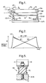
- a multi-point cell type weighing machine uses a weighing conveyor 10 serving as a weighing table, with a belt 10c stretched between a drive roller 10a, rotationally driven by a drive motor (not shown), and a follower roller 10b.
- Bearings 10d and 10e for the two rollers 10a and 10b are supported by a horizontally extending supporting plate 15 through vertically extending members 10f and 10g.
- the supporting plate 15 is in turn supported by a pair of scale cells 1 and 2 at its front and back positions.
- These scale cells 1 and 2 may be of the type comprising a deformable member having strain gauges attached thereto.
- a target object 20 to be weighed is arranged to be brought onto the weighing conveyor 10 from a delivery conveyor 40 disposed on the upstream side such that its weight can be measured by the pair of scale cells 1 and 2 while it is transported in the direction of arrow X on the weighing conveyor 10.
- Weight signals W1 and W2 indicative of the weight values measured by and outputted from the two scale cells 1 and 2 respectively, will generally look as shown in Fig. 2, changing with time as the target object 20 is transported, and its weight can be obtained from the sum W1+W2 of these two weight signals W1 and W2.
- the scale cells 1 and 2 are each disposed such that their axial lines 1c and 2c connecting their fixed ends 1a and 2a respectively with their free ends 1b and 2b are both perpendicular to the direction X of transportation of the object 20.
- These fixed ends 1a and 2a are supported by a base 5 (serving as "the floor F") respectively through fastening devices 3 and 4 to form cantilevers.
- Horizontal arms 8 and 9 are attached to the free ends 1b and 2b through fastening devices 3 and 4, respectively.
- Numerals 11, 12, 13 and 14 indicate holders for supporting the supporting plate 15 thereon.
- Each of the horizontally maintained arms 8 and 9 supports two or more (two in the example shown in Fig. 3) of these holders, each comprising a conically shaped member 11b, 12b, 13b or 14b fastened by a bolt 11a, 12a, 13a or 14a.
- These conically shaped members 11b, 12b, 13b and 14b are pointed at one end and the supporting plate 15 is supported from below by these pointed ends at its four corners.
- Two floor vibration detecting cells 161 and 162 are disposed near the scale cells 1 and 2, respectively, in the direction X of transportation. These two floor vibration detecting cells 161 and 162 are structured similarly to the scale cells 1 and 2 described above, each having one of its ends fastened through a fastening device 171 or 172 to the same base 5 and having a weight 181 or 182 fastened to the other end.
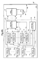
- the weighing machine is provided with a signal processing unit as schematically shown in Fig. 4A, including a CPU (such as a digital signal processor DSP) 25 shown more in detail in Fig. 4B.
- a CPU such as a digital signal processor DSP
- weight signals outputted from the scale cells 1 and 2 are amplified by amplifiers 22
- floor vibration detection signals outputted from the floor vibration detecting cells 161 and 162 are amplified by amplifiers 23, and these amplified signals are all inputted into a multiplexer 24, which is controlled by the CPU 25 through control signals c to selectively output these signals to an A/D converter 26.
- the digital weight signals will be indicated as W1 and W2
- the digital floor vibration detection signals will be indicated as Y1 and Y2.
- the signals W1, W2, Y1 and Y2 are received by the CPU 25, they are individually passed through a digital filtering means 28 having the characteristics of a low pass filter with cutoff frequency higher than 10Hz-20Hz for carrying out a filtering process, for example, by a convolution calculation of a known kind.
- the filtered signals outputted from the digital filtering means 28 will be denoted FW1, FW2, FY1 and FY2, respectively, as shown in Fig. 4B.
- a sensitivity adjusting process is carried out next on the filtered signals FW1, FW2, FY1 and FY2 by a sensitivity adjusting means 52 which includes sensitivity calculating means 54 and sensitivity correcting means 56.
- the sensitivity calculating means 54 calculates the output sensitivity ratio between the scale cell 1 and the floor vibration detecting cell 161 and the output sensitivity ratio between the scale cell 2 and the floor vibration detecting cell 162 on the basis of the differences in the spring constant and the load weight (including the tare) between the scale cell 1 (or 2) and the floor vibration detecting cell 161 (or 162).
- the sensitivity correcting means 56 corrects the filtered signals FY1 and FY2 from the floor vibration detecting cells 161 and 162 on the basis of the output sensitivity ratios thus calculated to output sensitivity-corrected signals SY1 and SY2.
- the filtered signals FY1 and FY2 may be corrected on the basis of these known ratios.
- corrections may similarly be effected on the filtered signals FW1 and FW2 from the scale cells 1 and 2 on the basis of the calculated or known output sensitivity ratios.
- the CPU 25 makes uses of the floor vibration adjusting means 42 and 44 to correct the effects of the floor vibrations on the weight signals to obtain vibration-corrected signals V1 and V2.
- the span-adjustment means 60 for correcting the output sensitivity ratio between the scale cells 1 and 2 when the machine is shipped from the factory or installed at the site of its operation.
- the span-adjustment means 60 is provided with a sensitivity calculating means 62, a sensitivity correcting means 64 and a mode-switching means 68.
- the mode-switching means 68 is for switching the mode of operation of the machine in response to a command from outside between a normal weighing mode and an output sensitivity ratio calculating mode.
- the machine In Fig. 4B, the machine is in the normal weighing mode with software switches 63 in the OFF positions as shown. If the switches 63 are in the ON positions, the machine will be in the output sensitivity calculating mode.
- the machine In general, the machine is switched to the output sensitivity calculating mode to calculate output sensitivity ratios when it is delivered from the factory or installed at a site but it is then switched to the normal weighing mode and kept in this mode thereafter.
- a standard weight 50 (with weight W) is placed at an arbitrary position on the supporting plate 15.
- This output sensitivity ratio S AB between the scale cells 1 and 2 is stored in a non-volatile memory 66 contained in the CPU 25.
- the sensitivity correcting means 64 uses this output sensitivity ratio S AB stored in the memory 66 to carry out a sensitivity correction process. This is done in the normal weighing mode of operation by multiplying the vibration-corrected signals V1 and V2 by the output sensitivity ratio S AB serving as the coefficient for sensitivity ratio correction and thereby outputting sensitivity-corrected signals DV1 and DV2.
- the vibration-corrected signals V1 and V2 are corrected according to the output sensitivity of the plurality of scale cells.
- ⁇ V jk indicates the output differential of the jth scale cell when the weight is placed for the kth time (or at the kth position), and S j indicates the output sensitivity of the jth scale cell.
- S V ⁇ 1W and the output sensitivity of each scale cell can be determined.
- the weight must be placed at N different positions in order to obtain N mutually independent simultaneous equations.
- the supporting table may tend to tilt or experience a strain.
- the supporting table 15 since the supporting table 15 is supported by pointed ends of the conically shaped members 11b, 12b, 13b and 14b, the vertical components of the forces therethrough are directly transmitted to the scale cells 1 and 2 but their horizontal components contribute only to the sliding of the members 11b, 12b, 13b and 14b. Similarly, no torque which may be experienced by the supporting table 15 will contribute a vertical force.
- the scale cells output weight signals representing partial weights of the target object distributed according to the distances of the center of gravity of the target object from the scale cells 1 and 2.
- Fig. 5 shows at 69 another embodiment of the plate supporting members 11, 12, 13 and 14 characterized as having attaching devices 71 and 72 such as bolts attached to mutually opposite ends of an elastic member 70 made, for example, of rubber, one of the attaching devices (71) being adapted to be fastened to the supporting table 15 and the other attaching device (72) to either of the arms 8 and 9.
- attaching devices 71 and 72 such as bolts attached to mutually opposite ends of an elastic member 70 made, for example, of rubber
- one of the attaching devices (71) being adapted to be fastened to the supporting table 15 and the other attaching device (72) to either of the arms 8 and 9.
- the CPU 25 serves to add the sensitivity-corrected signals DV1 and DV2 together by an adder 46 as partial weight data representing the shared load on the scale cells 1 and 2, outputting an added weight signal BW to a stabilization calculating means 36 for carrying out stabilization calculations and outputting a stabilized added signal AW, as shown in Fig. 4A.
- the present invention makes it possible to quickly obtain stabilized output data which have been corrected according to the output sensitivity of the scale cells 1 and 2 and of which low-frequency floor vibration components are attenuated, independently of whether the target object is placed at an off-center position on the weighing plate.
- the value of a measured weight thus obtained may be displayed on a display device (not shown) or printed out by a printer (not shown).
- Fig. 4B shows a CPU 25 with digital filtering means 28 on the upstream side of the adder 46
- the filtering operation may be carried out after signals are added by the adder 46.
- a single A/D converter 26 is shown in Fig. 4A, a plurality of A/D converters may be provided, each corresponding to one of the scale cells or the floor vibration detecting cells.
- the sensitivity correcting means 64 was shown as carrying out corrections on the vibration-corrected signals V1 and V2, the sensitivity correction may be effected on weight signals before the vibration corrections.
- Multi-point cell type weighing machines may be characterized as carrying out floor vibration correction by calculating the vibration mode of the floor.
- Fig. 6 shows the structure of the scale and floor vibration detecting cells 1 (2) and 16 (hereinafter referred to as "the load cell") of the weighing machine described above.
- a load cell of this type is provided with four strain gauges 53 attached individually near one of four notches 51 formed in a central opening therethrough to detect its deformation in terms of the strains measured thereby.
- These four strain gauges 53 form a Wheatstone bridge (not shown) which is adapted such that its output changes only if the load cell 1 (2, 16) is deformed into a parallelogram as shown by a broken line. In other words, there is no change in its output if the load cell 1 (2, 16) undergoes any other kind of deformation.
- the movement of the X-Y plane can be described in terms of the rotation around the X-axis, the rotation around the Y-axis and the motion along an axis (the Z-axis) perpendicular to both the X-axis and the Y-axis.
- the other modes of motion will not be discussed here because they are not detected by the load cell 1 (2, 16).
- V P (t) xA(t)+yB(t)+C(t)
- A(t), B(t) and C(t) in (8) it is theoretically sufficient to detect the floor motion at three positions not in a collinear relationship and solve linear simultaneous equations with three unknowns. In practice, however, motion is detected at more than three positions because the output from each load sensor contains some measurement errors, and A(t), B(t) and C(t) may be obtained preferably by a method of least squares.
- a method such as the one described above, of detecting the vibration modes of a floor and reducing the vibration components of scale cells at arbitrary positions thereon is referred to as a multi-point AFV (anti-floor vibration) process.
- AFV anti-floor vibration
- scale cells are disposed on a plane, or two-dimensionally, floor vibrations are detected by floor vibration detecting cells at three or more positions not in collinear relationship on the plane.
- the vibration modes of the floor are detected from these individual vibrations thus detected, and the vibration components of the floor at the positions of the scale cells are obtained therefrom and subtracted from the weight values outputted from these scale cells.
- scale cells are aligned on a single line, or one-dimensionally, floor vibrations are detected by floor vibration detecting cells at two or more different positions on the line connecting the scale cells, and the vibration components of the floor at the positions of the scale cells are similarly obtained and subtracted from the weight values being outputted therefrom. Vibration components can be subtracted similarly when the scale cells are scattered all over.
- Figs. 8A and 8B show the signal processing unit of another weighing machine of the multi-point cell type according to a second embodiment of the invention characterized as being adapted to calculate the mode of floor vibrations.
- the weighing machine shown as an example in Figs. 8A and 8B, has a plural number m of scale cells 1-m, another plural number n of floor vibration detecting cells 161-16 n , amplifiers 22 and 23, a multiplexer 24, an A/D converter 26 and a CPU 25'.
- the CPU 25' which is shown in Fig.
- the floor vibration calculating means 84 is provided with a floor vibration mode calculating means for calculating the mode of vibrations of the floor and a point vibration calculating means for calculating the floor vibration at the known positions of the scale cells from the calculated mode of vibrations of the floor.
- the signal processing unit of Figs. 8A and 8B are the same as that shown in Figs. 4A and 4B.
- the floor vibration detecting cells 161 and 162 are required to be placed adjacent to the corresponding one of the scale cells 1 and 2 according to the first embodiment of the invention shown in Figs. 4A and 4B, the floor vibration detecting cells 161-16 n may be placed at any positions as long as they are on the same floor F as the scale cells 1-m.
- the second embodiment of the invention is advantageous in that there is an increased degree of freedom in the design of a machine because the floor vibration detecting calls 161-16 n may be farther away from any of the scale cells 1-m.
- weight signals outputted from the scale cells 1-m and floor vibration detection signals outputted from the floor vibration detecting cells 161-16 n are amplified by the amplifiers 22 and 23, respectively, they are passed through the multiplexer 24, converted into digital signals W1-W m (digital weight signals) and Y1-Y n (digital floor vibration detection signals), respectively, and inputted to the CPU 25'.
- the CPU 25' uses digital filtering means 28 to carry out a filtering process on these signals W1-W m and Y1-Y n and produce filtered signals FW1-FW m and FY1-FY n .
- the vibration components of the filtered floor vibration detection signals FY1-FY n are utilized by the floor vibration mode calculating means of the floor vibration calculating means 84 to calculate the vibration component V P (t) of (8).
- the mode of floor vibration thus calculated is used by the point vibration calculating means to carry out a point vibration calculating process by producing displacement signals M1-M m indicative of the vertical displacements of the floor at known positions of the scale cells 1-m.
- a sensitivity adjusting means 52 carries out a sensitivity adjusting process on these displacement signals M1-M m and thereby outputs sensitivity-adjusted displacement signals S1-S m .
- the floor vibration correcting means 82 corrects individually the filtered signals FW1-FW m outputted from the scale cells 1-m by subtracting the displacements according to the displacement signals S1-S m from the filtered signals FW1-FW m , thereby outputting vibration-corrected signals V1-V m .
- the vibration mode of the floor is determined from the vibration components of floor vibration detection signals Y1-Y n outputted from the plurality of floor vibration detecting cells 161-16 n set on the same floor as the scale cells 1-m, and the vertical displacements of the floor at the positions of the scale cells 1-m are subtracted from the individual weight signals W1-W m to output the vibration-corrected signals V1-V m . Since the subtractions and corrections are effected digitally according to the embodiment described above, more accurate corrections are possible than if they were carried out by using analog circuits because there are fluctuations in the characteristics of individual parts and elements of analog circuits.
- Fig. 9 shows an example of mode of floor vibration being detected by floor vibration detecting cells 161-163 at three positions on the floor F.
- the floor vibrations of the floor F at the positions of the scale cells 1-m are calculated from the slope of the surface 103, representing the vibration mode of the floor F.
- Fig. 8A shows a single A/D converter 26, a plurality of such A/D converters may be used, one for each of the scale and floor vibration detecting cells.
- analog filters may be used instead of, or in addition to, the digital filtering means 28 of Fig. 8B. In such a situation, the analog filters are connected at positions 39 shown by dotted lines.
- Fig. 10 shows still another multi-point cell type weighing machine according to a third embodiment of the invention characterized as having only one floor vibration detecting cell 16 at an arbitrary position between a plurality (two in the example shown in Fig. 10) of scale cells 1 and 2 where a target object is intended to be weighed. As shown in Fig.
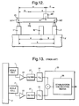
- the signal processing unit of this weighing machine includes amplifiers 22 and 23, a multiplexer 24 and an A/D converter 26 such that weight signals from the scale cells 1 and 2 are amplified by the amplifiers 22, an analog floor vibration detection signal from the single floor vibration detecting cell 16 is amplified by amplifier 23, and these amplified signals are passed through the multiplexer 24 into the A/D converter 26 to be converted into digital weight and analog signals W1, W2 and Y, respectively, and to be inputted to a CPU 25''. As shown in Fig. 11B, the CPU 25'' carries out filtering processes on these signals by digital filtering means 28 and outputs filtered signals FW1, FW2 and FY therefrom.
- the CPU 25'' carries out a sensitivity adjusting process on these filtered signals FW1, FW2 and FY by a sensitivity adjusting means 52.
- sensitivity correction between the scale cells 1 and 2 is effected by a span adjusting means 60 on the sensitivity-adjusted filtered signals FW1 and FW2, they are added together by an adding means 46 to produce an added signal TW.
- a floor vibration adjusting means 48 subtracts the sensitivity-adjusted filtered signal FY from the added signal TW to thereby output an added weight signal BW.
- a stabilization calculation is carried out on this added weight signal BW and a stabilized weight signal AW is outputted.
- Sensitivity adjustment is thus carried out between each scale cell 1 (2) and the floor vibration detecting cell 16 to reduce the floor vibration components and to provide stabilized output data adjusted according to the output sensitivity ratio between the scale cells 1 and 2.
- the sensitivity adjusting means 52 for carrying out sensitivity adjusting processes on the filtered signals FW1, FW2 and FY includes sensitivity' calculating means 54 and sensitivity correcting means 56. Their operations will be explained in detail next with reference to Fig. 12, which is a schematic side view of the weighing machine of Figs. 10, 11A and 11B.
- M G indicates the weight and the position of the center of gravity of the weighing conveyor 10
- M1 and M2 are the loads on the scale cells 1 and 2
- L is the length of the weighing conveyor 10
- m and n are the distances of the center of gravity M G from the scale cells 1 and 2
- x and y are the distances of the target object 20 of weight M from the scale cells 1 and 2
- a and b are the distances of the floor vibration detecting cell 16 from the scale cells 1 and 2.
- the sensitivity correcting means 56 carries out sensitivity correction process on the filtered signals FW1, FW2 and FY. If the outputs from the scale cells due to the floor vibrations are Z1 and Z2, the floor vibration portion Z16 (outputted value of the filtered signal FY) at the output sensitivity of the floor vibration detecting cell 16 at its position obtained from Z1 and Z2 is:
- the weight M of the target object 20 can be obtained by a very simple formula, and this makes a high-speed weighing possible. Since only one floor vibration detecting cell 16 is employed, furthermore, the structure of the machine is simplified.
- the target object 20 is weighed while being transported on a weighing conveyor in all of the embodiments of the invention described above, this is not intended to limit the scope of the invention. This invention can be equally well applied to situations where the target object 20 is weighed in a stationary state.
- A/D converter need not be placed downstream of the multiplexer in any of the embodiments.
- the holders 11, 12, 13 and 14 for supporting the supporting plate 15 need not necessarily be structured as shown in Fig. 5.
Abstract
Description
- This invention relates to a weighing machine of the so-called multi-point cell type, characterized as having a weighing table supported by a plurality of scale cells in which the weight signals from these scale cells are added to measure the weight of a target object placed on the weighing table. In particular, this invention relates to such a machine capable of high-speed weighing.
- Weighing machines of the multi-point cell type, as disclosed in Japanese Patent Publication Tokko 63-285941, have been in use for measuring the weight of a large or heavy target object, such as an automobile, by supporting a weighing table by a plurality of weighing cells and adding the weight signals outputted from the individual cells. Compared to weighing machines with only one cell adapted to measure the entire weight of a target object, weighing machines of the multiple-point cell type are advantageous because the size of the weighing table can be made larger since many weighing cells of about the same size can be used to support it. The scale cells are typically comprised of a deformable body with strain gauges attached thereon.
- When such a weighing machine is used to measure the weight of a target object moving on a weighing conveyor, mechanical vibrations are caused to the plurality of scale cells due, for example, to the shock associated with the shift of the weight of the target object from a conveyor for its transportation to the weighing conveyor. In view of the above, it has been known, as shown in Fig. 13, to use
amplifiers 22, filters (with cutoff frequency 5Hz-10Hz) 27 and A/D converters 24 to process weight signals outputted from a plurality ofscale cells CPU 25 and to thereafter extract a filtered signal with its high-frequency vibration components attenuated. This process is illustrated in Fig. 14. - It takes, however, a significantly long time (referred to as the stabilization time S), say, of about 200msec until such a filtered signal becomes stabilized, and this has indeed been a source of problem in the attempt to achieve high-speed weighing. In view of the above, it has been known to carry out a stabilization routine on weight data in order to speed up a weighing process. For example, if there is a set of time-sequenced signal values a₁, a₂, a₃, a₄, a₅, a₆, ... , a final equilibrium value to which the signal values are expected to converge, may be predicted by first taking the average of a₁, a₂ and a₃, next taking the average of a₂, a₃ and a₄, then taking the average of a₃, a₄ and a₅, and so forth. In this manner, a partially stabilized value can be obtained within a shorter time period, say, of about 150msec without waiting for the full stabilization time S. The overall weighing efficiency is thereby improved if such partially stabilized values are used as the stabilized weight value.
- There are situations, however, where scale cells pick up the effects of environmental vibrations (to be referred to simply as "the floor vibrations") such as vibrations of the ground, building, floor and/or table on which they are set. In general, the floor vibrations have frequencies lower than those of the weighing system. Thus, they are passed through the
digital filter 27 and added to the weight signals which are outputted, as shown in Fig. 15. If the averaging method described above were applied to this situation by considering time-sequenced signal values b₁, b₂, b₃, b₄, b₅, b₆, ... , the convergence would be slow because of the effects of these low-frequency components. If the cutoff frequency of thedigital filters 27 is lowered in an attempt to reduce the effects of the floor vibrations, however, this will tend to increase the stabilization time S, adversely affecting the capability of the system as a whole. - Another problem to be taken into consideration is the difference in sensitivity among the plurality of scale cells, due, for example, to the fluctuations in the resistance of the strain gauges. In other words, sensitivity of each scale cell must be adjusted. Japanese Patent Publication Tokkai 63-282616 taught the technology of preliminarily measuring the sensitivity of each scale cell, storing it in a memory device and correcting weight data from the scale cells by using the stored sensitivity characteristics. According to this technology, however, it is necessary to apply the same load to all scale cells. After a weighing table is attached to the scale cells, it is practically impossible to apply the same load equally to all scale cells when the object to be weighed is incorrectly positioned.
- It is therefore an object of this invention to provide a multi-point cell type weighing machine capable of weighing objects quickly and accurately.
- A multi-point cell type weighing machine according to this invention, with which the above and other objects can be accomplished, may be characterized not only as supporting a weighing table by a plurality of scale cells and being adapted to add weight signals from the individual cells to thereby obtain a sum signal representing the weight of an object placed on the weighing table, but also as comprising floor vibration detecting cells set on the same floor as the scale cells, floor vibration adjusting means for outputting a corrected signal by adjusting the weight signals or the sum signal with the vibration components of vibration detection signals outputted from the floor vibration detecting cells to thereby correcting errors in the weight signals due to the floor vibrations, sensitivity calculating means for calculating output sensitivity ratio among the scale cells from outputted values from the individual weighing cells as a standard weight is placed sequentially at more different positions on the weighing table than the number of the scale cells, and sensitivity correcting means for correcting the aforementioned weight signal based on the output sensitivity ratio.
- According to one embodiment of the invention, one of the floor vibration detecting cells is positioned near each of the scale cells. According to another embodiment of the invention, a plurality of floor vibration detecting cells are provided and the floor vibration adjusting means includes floor vibration calculating means for detecting vibration mode of the floor from the vibration components of the floor vibration detection signals outputted from the plurality of floor vibration detecting cells and thereby calculating vertical displacements of the floor at the positions of the scale cells and floor vibration correcting means for generating a corrected signal by subtracting components of the floor vibrations from the weight signals. According to a third embodiment of the invention, there is only one floor vibration detecting cell and it is positioned at a center position of the individual scale cells.
- With a weighing machine thus structured according to the present invention, errors due to the floor vibrations on weight signals from the scale cells, when a target object is placed on the weighing table, are corrected by placing floor vibration detecting cells on the same floor as the scale cells and the sum signal is obtained after corrections are effected on the basis of the sensitivity ratio among the scale cells. Since the floor vibration components are reduced and the sum signal corrected according to the outputted sensitivity ratio is outputted, accurate weighing can be carried out quickly by a stabilization calculation process.
- If each of the scale cells has one of the floor vibration detecting cells at a nearby position, each pair of mutually near cells may be considered to vibrate in the same mode. Thus, the effects of the floor vibrations can be immediately removed by directly subtracting the corresponding floor vibration detecting signal from each weight signal.
- In the case of a weighing machine according to the second embodiment of the invention, the mode of vibrations of the floor is detected from the vibration components of the floor vibration detection signals outputted from the plurality of floor vibration detecting cells and the vertical displacement of the floor is calculated therefrom where each of the scale cells is positioned. The weight signals are corrected thereby and corrected signals are generated and added together. Thus, weight signals can be corrected accurately even in a situation where the floor is vibrating differently at the position of a scale cell and that of the corresponding floor vibration detecting cell. Since the limitations on where to set the floor vibration detecting cells become less stringent in this case, there is an increased degree of freedom in the design choice of the weighing machine. If a single floor vibration detecting cell is used at a center, on the other hand, the structure of the weighing machine becomes simpler.
- The accompanying drawings, which are incorporated in and form a part of this specification, illustrate embodiments of the invention and, together with the description, serve to explain the principles of the invention. In the drawings:
- Fig. 1 is a schematic side view of a multi-point cell type weighing machine according to an embodiment of the invention;
- Fig. 2 is a signal waveform diagram of a weight signal outputted by the weighing machine of Fig. 1;
- Fig. 3 is a diagonal view of a portion of the weighing machine of Fig. 1;
- Figs. 4A and 4B are block diagrams of the signal processing unit of the weighing machine of Fig. 1;
- Fig. 5 is a sectional view of another plate supporting member according to the invention;
- Fig. 6 shows the shape and deformation of a load cell for explaining the theory of AFV (anti-floor vibration) technology;
- Fig. 7 shows the positioning of the load cell of Fig. 6;
- Figs. 8A and 8B are block diagrams of the signal processing unit of another weighing machine according to a second embodiment of the invention;
- Fig. 9 is a schematic for showing an example of vibration mode of a floor;
- Fig. 10 is a diagonal view of a portion of still another multi-point cell type weighing machine according to a third embodiment of the invention;
- Figs. 11A and 11B are block diagrams of the signal processing unit of the weighing machine of Fig. 10;
- Fig. 12 is a schematic side view of the weighing machine of Figs. 10, 11A and 11B;
- Fig. 13 is a block diagram of a prior art multi-point cell type weighing machine;
- Fig. 14 is a graph of stabilizing signal; and
- Fig. 15 is a graph of stabilizing signal with floor vibrations.
- Throughout herein, those components which are substantially identical, although of machines according to different embodiments, are indicated by the same numeral.
- As schematically shown in Fig. 1, a multi-point cell type weighing machine according to an embodiment of the invention uses a weighing
conveyor 10 serving as a weighing table, with abelt 10c stretched between adrive roller 10a, rotationally driven by a drive motor (not shown), and afollower roller 10b.Bearings rollers plate 15 through vertically extending members 10f and 10g. The supportingplate 15 is in turn supported by a pair ofscale cells scale cells - A
target object 20 to be weighed is arranged to be brought onto the weighingconveyor 10 from adelivery conveyor 40 disposed on the upstream side such that its weight can be measured by the pair ofscale cells weighing conveyor 10. Weight signals W₁ and W₂, indicative of the weight values measured by and outputted from the twoscale cells target object 20 is transported, and its weight can be obtained from the sum W₁+W₂ of these two weight signals W₁ and W₂. Because theconveyor 10 experiences a shock when thetarget object 20 is transferred from thedelivery conveyor 40 onto theweighing conveyor 10, mechanical vibrations (or the weighing system vibrations) are generated in thescale cells conveyor 10. This is indicated by numeral 101 in Fig. 2. - As shown more in detail in Fig. 3, the
scale cells axial lines free ends object 20. These fixed ends 1a and 2a are supported by a base 5 (serving as "the floor F") respectively throughfastening devices Horizontal arms fastening devices -
Numerals plate 15 thereon. Each of the horizontally maintainedarms member bolt members plate 15 is supported from below by these pointed ends at its four corners. - Two floor
vibration detecting cells scale cells vibration detecting cells scale cells fastening device 17₁ or 17₂ to thesame base 5 and having aweight - Although not shown in Fig. 1 or 3, the weighing machine is provided with a signal processing unit as schematically shown in Fig. 4A, including a CPU (such as a digital signal processor DSP) 25 shown more in detail in Fig. 4B. With reference first to Fig. 4A, weight signals outputted from the
scale cells amplifiers 22, floor vibration detection signals outputted from the floorvibration detecting cells amplifiers 23, and these amplified signals are all inputted into amultiplexer 24, which is controlled by theCPU 25 through control signals c to selectively output these signals to an A/D converter 26. The digital weight signals will be indicated as W₁ and W₂, and the digital floor vibration detection signals will be indicated as Y₁ and Y₂. - When the signals W₁, W₂, Y₁ and Y₂ are received by the
CPU 25, they are individually passed through a digital filtering means 28 having the characteristics of a low pass filter with cutoff frequency higher than 10Hz-20Hz for carrying out a filtering process, for example, by a convolution calculation of a known kind. The filtered signals outputted from the digital filtering means 28 will be denoted FW₁, FW₂, FY₁ and FY₂, respectively, as shown in Fig. 4B. - A sensitivity adjusting process is carried out next on the filtered signals FW₁, FW₂, FY₁ and FY₂ by a sensitivity adjusting means 52 which includes
sensitivity calculating means 54 andsensitivity correcting means 56. The sensitivity calculating means 54 calculates the output sensitivity ratio between thescale cell 1 and the floorvibration detecting cell 16₁ and the output sensitivity ratio between thescale cell 2 and the floorvibration detecting cell 16₂ on the basis of the differences in the spring constant and the load weight (including the tare) between the scale cell 1 (or 2) and the floor vibration detecting cell 16₁ (or 16₂). Thesensitivity correcting means 56 corrects the filtered signals FY₁ and FY₂ from the floorvibration detecting cells - If the output sensitivity ratios between the
scale cell 1 and the floorvibration detecting cell 16₁ and between thescale cell 2 and the floorvibration detecting cell 16₂ are preliminarily known, the filtered signals FY₁ and FY₂ may be corrected on the basis of these known ratios. As another variation of the above, corrections may similarly be effected on the filtered signals FW₁ and FW₂ from thescale cells - Next, a floor vibration adjusting means 42 carries out a subtraction process, subtracting the sensitivity-corrected signal SY₁ from the filtered signals FW₁ from the
scale cell 1 and thereby outputting vibration-corrected signal V₁ representing the weight on thescale cell 1 from which the effects of the vertical vibrations of the floor at the position of thescale cell 1 has been removed, or FW₁ - SY₁ = V₁. Similarly, another floor vibration adjusting means 44 carries out another subtraction process, subtracting the sensitivity-corrected signal SY₂ from the filtered signals FW₂ from thescale cell 2 and thereby outputting vibration-corrected signal V₂ representing the weight on thescale cell 2 from which the effects of the vertical vibrations of the floor at the position of thescale cell 2 has been removed, or FW₂ - SY₂ = V₂. In summary, theCPU 25 makes uses of the floor vibration adjusting means 42 and 44 to correct the effects of the floor vibrations on the weight signals to obtain vibration-corrected signals V₁ and V₂. - When a plurality of scale cells are used, as in the example described above, it is necessary to adjust the output sensitivity of the
scale cells 1 and 2 (or to carry out a span adjustment) because their output sensitivity and the gains of theamplifiers scale cells sensitivity correcting means 64 and a mode-switching means 68. The mode-switching means 68 is for switching the mode of operation of the machine in response to a command from outside between a normal weighing mode and an output sensitivity ratio calculating mode. In Fig. 4B, the machine is in the normal weighing mode withsoftware switches 63 in the OFF positions as shown. If theswitches 63 are in the ON positions, the machine will be in the output sensitivity calculating mode. In general, the machine is switched to the output sensitivity calculating mode to calculate output sensitivity ratios when it is delivered from the factory or installed at a site but it is then switched to the normal weighing mode and kept in this mode thereafter. - Next, there will be described the operations of the sensitivity calculating means 62 in the output sensitivity calculating mode. First, a standard weight 50 (with weight W) is placed at an arbitrary position on the supporting
plate 15. - If the output differentials from the vibration-corrected signals V₁ and V₂ are △VA1 and △
V B₁, they are related to the output sensitivity SA and SB of thescale cells 
- If the output differentials are △VA2 and △VB2 when the
standard weight 50 is moved to another arbitrary position on the supportingplate 15,
- From these two equations, one can calculate the output sensitivity ratio SAB between the
scale cells 
- Thus, the output sensitivity of the
scale cells 

- The value of this output sensitivity ratio SAB between the
scale cells non-volatile memory 66 contained in theCPU 25. - Next, after the mode of operation is switched from the output sensitivity calculating mode to the normal weighing mode, the
sensitivity correcting means 64 uses this output sensitivity ratio SAB stored in thememory 66 to carry out a sensitivity correction process. This is done in the normal weighing mode of operation by multiplying the vibration-corrected signals V₁ and V₂ by the output sensitivity ratio SAB serving as the coefficient for sensitivity ratio correction and thereby outputting sensitivity-corrected signals DV₁ and DV₂. Thus, the vibration-corrected signals V₁ and V₂ are corrected according to the output sensitivity of the plurality of scale cells. - Thee method according to this invention has been explained above with reference to an example with only two
scale cells 
or a matrix equation
where

- In the above, △Vjk indicates the output differential of the jth scale cell when the weight is placed for the kth time (or at the kth position), and Sj indicates the output sensitivity of the jth scale cell. Thus, one obtains from (6A)

and the output sensitivity of each scale cell can be determined. In summary, the weight must be placed at N different positions in order to obtain N mutually independent simultaneous equations. - In general, if a target object to be weighed is placed at an off-center position on a supporting table, the supporting table may tend to tilt or experience a strain. According to this invention, since the supporting table 15 is supported by pointed ends of the conically shaped
members scale cells members scale cells - Fig. 5 shows at 69 another embodiment of the
plate supporting members devices elastic member 70 made, for example, of rubber, one of the attaching devices (71) being adapted to be fastened to the supporting table 15 and the other attaching device (72) to either of thearms elastic member 70. As a result, only vertical components of forces are communicated to the scale cells. In other words, accurate weighing can be accomplished independently of the position at which the target object may be placed on the supporting table. If theplate supporting members 69 are made of a vibration-absorbing rubber or alloy material, furthermore, they can absorb external vibrations and thereby prevent errors due to vibrations. - As shown further in Fig. 4B, the
CPU 25 serves to add the sensitivity-corrected signals DV₁ and DV₂ together by anadder 46 as partial weight data representing the shared load on thescale cells scale cells - It now goes without saying that many variation and modifications are possible on the embodiment of the invention described above, For example, although Fig. 4B shows a
CPU 25 with digital filtering means 28 on the upstream side of theadder 46, the filtering operation may be carried out after signals are added by theadder 46. As another example, although a single A/D converter 26 is shown in Fig. 4A, a plurality of A/D converters may be provided, each corresponding to one of the scale cells or the floor vibration detecting cells. As still another example, although thesensitivity correcting means 64 was shown as carrying out corrections on the vibration-corrected signals V₁ and V₂, the sensitivity correction may be effected on weight signals before the vibration corrections. - Multi-point cell type weighing machines according to a second embodiment of the invention may be characterized as carrying out floor vibration correction by calculating the vibration mode of the floor. Before a machine according to this embodiment is described, however, its basic principle will be explained first.
- Fig. 6 shows the structure of the scale and floor vibration detecting cells 1 (2) and 16 (hereinafter referred to as "the load cell") of the weighing machine described above. A load cell of this type is provided with four
strain gauges 53 attached individually near one of fournotches 51 formed in a central opening therethrough to detect its deformation in terms of the strains measured thereby. These fourstrain gauges 53 form a Wheatstone bridge (not shown) which is adapted such that its output changes only if the load cell 1 (2, 16) is deformed into a parallelogram as shown by a broken line. In other words, there is no change in its output if the load cell 1 (2, 16) undergoes any other kind of deformation. Thus, when there is a relative deformation between the fixed side la where it is attached to the floor and thefree side 1b where a load is applied (indicated by an arrow), only the component of a parallelogrammic deformation is detected. When such load cells are used, therefore, only the perpendicular (vertical) components of the vibration modes of the floor need to be considered. - Consider, for example, a load cell 1 (2, 16) affixed at a position P(x, y) on an X-Y plane as shown in Fig. 7. The movement of the X-Y plane can be described in terms of the rotation around the X-axis, the rotation around the Y-axis and the motion along an axis (the Z-axis) perpendicular to both the X-axis and the Y-axis. The other modes of motion will not be discussed here because they are not detected by the load cell 1 (2, 16). Now, let the motion in the Z-direction caused by a rotary motion around the X-axis be denoted by B(t), that caused by a rotary motion around the Y-axis by A(t) and the motion in the direction of the Z-axis by C(t). Of the output signal from the load cell at position P, the component VP(t) contributed by the floor vibration is given as follows:

- In order to obtain the values of A(t), B(t) and C(t) in (8), it is theoretically sufficient to detect the floor motion at three positions not in a collinear relationship and solve linear simultaneous equations with three unknowns. In practice, however, motion is detected at more than three positions because the output from each load sensor contains some measurement errors, and A(t), B(t) and C(t) may be obtained preferably by a method of least squares.
- In general, a method, such as the one described above, of detecting the vibration modes of a floor and reducing the vibration components of scale cells at arbitrary positions thereon is referred to as a multi-point AFV (anti-floor vibration) process. If scale cells are disposed on a plane, or two-dimensionally, floor vibrations are detected by floor vibration detecting cells at three or more positions not in collinear relationship on the plane. The vibration modes of the floor are detected from these individual vibrations thus detected, and the vibration components of the floor at the positions of the scale cells are obtained therefrom and subtracted from the weight values outputted from these scale cells. If the scale cells are aligned on a single line, or one-dimensionally, floor vibrations are detected by floor vibration detecting cells at two or more different positions on the line connecting the scale cells, and the vibration components of the floor at the positions of the scale cells are similarly obtained and subtracted from the weight values being outputted therefrom. Vibration components can be subtracted similarly when the scale cells are scattered all over.
- Figs. 8A and 8B show the signal processing unit of another weighing machine of the multi-point cell type according to a second embodiment of the invention characterized as being adapted to calculate the mode of floor vibrations. The weighing machine, shown as an example in Figs. 8A and 8B, has a plural number m of scale cells 1-m, another plural number n of floor vibration detecting cells 16₁-16n,
amplifiers multiplexer 24, an A/D converter 26 and a CPU 25'. For the convenience of explanation, the individual components which are substantially identical to those shown in Figs. 4A and 4B and explained above with reference thereto are herein indicated by the same numeral and their individual structures and functions will not be described again. The CPU 25', which is shown in Fig. 8A, includes a floor vibration adjusting means 80 provided with a floor vibration correcting means 82 and a floor vibration calculating means 84. The floor vibration calculating means 84 is provided with a floor vibration mode calculating means for calculating the mode of vibrations of the floor and a point vibration calculating means for calculating the floor vibration at the known positions of the scale cells from the calculated mode of vibrations of the floor. In other respect, the signal processing unit of Figs. 8A and 8B are the same as that shown in Figs. 4A and 4B. - Although the floor
vibration detecting cells scale cells - With reference still to Fig. 8A and 8B, after weight signals outputted from the scale cells 1-m and floor vibration detection signals outputted from the floor vibration detecting cells 16₁-16n are amplified by the
amplifiers multiplexer 24, converted into digital signals W₁-Wm (digital weight signals) and Y₁-Yn (digital floor vibration detection signals), respectively, and inputted to the CPU 25'. The CPU 25' uses digital filtering means 28 to carry out a filtering process on these signals W₁-Wm and Y₁-Yn and produce filtered signals FW₁-FWm and FY₁-FYn. - The vibration components of the filtered floor vibration detection signals FY₁-FYn are utilized by the floor vibration mode calculating means of the floor vibration calculating means 84 to calculate the vibration component VP(t) of (8). After this floor vibration mode calculating process is carried out, the mode of floor vibration thus calculated is used by the point vibration calculating means to carry out a point vibration calculating process by producing displacement signals M₁-Mm indicative of the vertical displacements of the floor at known positions of the scale cells 1-m. A sensitivity adjusting means 52 carries out a sensitivity adjusting process on these displacement signals M₁-Mm and thereby outputs sensitivity-adjusted displacement signals S₁-Sm.
- From the displacement signals S₁-Sm thus calculated on the basis of the mode of floor vibration, the floor vibration correcting means 82 corrects individually the filtered signals FW₁-FWm outputted from the scale cells 1-m by subtracting the displacements according to the displacement signals S1-Sm from the filtered signals FW₁-FWm, thereby outputting vibration-corrected signals V₁-Vm.
- In summary, the vibration mode of the floor is determined from the vibration components of floor vibration detection signals Y₁-Yn outputted from the plurality of floor vibration detecting cells 16₁-16n set on the same floor as the scale cells 1-m, and the vertical displacements of the floor at the positions of the scale cells 1-m are subtracted from the individual weight signals W₁-Wm to output the vibration-corrected signals V₁-Vm. Since the subtractions and corrections are effected digitally according to the embodiment described above, more accurate corrections are possible than if they were carried out by using analog circuits because there are fluctuations in the characteristics of individual parts and elements of analog circuits.
- Fig. 9 shows an example of mode of floor vibration being detected by floor vibration detecting cells 16₁-16₃ at three positions on the floor F. The floor vibrations of the floor F at the positions of the scale cells 1-m are calculated from the slope of the
surface 103, representing the vibration mode of the floor F. - There are situations where the floor vibrations are so small that the accuracy of measured weight is adversely affected by errors in the calculations, for example, in an attempt to effect corrections. For this reason, the process of correcting effects of floor vibrations is automatically inhibited if the vibration components of the outputs from the floor vibration detecting cells are smaller than a predefined standard level. Although Fig. 8A shows a single A/
D converter 26, a plurality of such A/D converters may be used, one for each of the scale and floor vibration detecting cells. Moreover, analog filters may be used instead of, or in addition to, the digital filtering means 28 of Fig. 8B. In such a situation, the analog filters are connected atpositions 39 shown by dotted lines. - Fig. 10 shows still another multi-point cell type weighing machine according to a third embodiment of the invention characterized as having only one floor
vibration detecting cell 16 at an arbitrary position between a plurality (two in the example shown in Fig. 10) ofscale cells amplifiers multiplexer 24 and an A/D converter 26 such that weight signals from thescale cells amplifiers 22, an analog floor vibration detection signal from the single floorvibration detecting cell 16 is amplified byamplifier 23, and these amplified signals are passed through themultiplexer 24 into the A/D converter 26 to be converted into digital weight and analog signals W₁, W₂ and Y, respectively, and to be inputted to a CPU 25''. As shown in Fig. 11B, the CPU 25'' carries out filtering processes on these signals by digital filtering means 28 and outputs filtered signals FW₁, FW₂ and FY therefrom. - Next, the CPU 25'' carries out a sensitivity adjusting process on these filtered signals FW₁, FW₂ and FY by a sensitivity adjusting means 52. After sensitivity correction between the
scale cells vibration detecting cell 16 to reduce the floor vibration components and to provide stabilized output data adjusted according to the output sensitivity ratio between thescale cells - As shown in Fig. 11B, the sensitivity adjusting means 52 for carrying out sensitivity adjusting processes on the filtered signals FW₁, FW₂ and FY includes sensitivity' calculating means 54 and
sensitivity correcting means 56. Their operations will be explained in detail next with reference to Fig. 12, which is a schematic side view of the weighing machine of Figs. 10, 11A and 11B. - The operations of the sensitivity calculating means 54 will be explained first. With reference to Fig. 12, MG indicates the weight and the position of the center of gravity of the weighing
conveyor 10, M₁ and M₂ are the loads on thescale cells conveyor 10, m and n are the distances of the center of gravity MG from thescale cells target object 20 of weight M from thescale cells vibration detecting cell 16 from thescale cells scale cells vibration detecting cells weight 18 on the floorvibration detecting cell 16 is M₁₆, the output sensitivity ratios α₁ and α₂ of thescale cells vibration detecting cell 16 are given by α₁ = M₁k₁₆/M₁₆k₁ and α₂ = M₂k₁₆/M₁₆k₂ if it is assumed that the frequencies of the floor vibrations detected by the floorvibration detecting cell 16 are sufficiently lower than the characteristic frequencies of the cell systems and hence the output sensitivity ratios are not influenced by the characteristic vibrations. - On the basis of the output sensitivity ratios α₁ and α₂ thus calculated, the sensitivity correcting means 56 carries out sensitivity correction process on the filtered signals FW₁, FW₂ and FY. If the outputs from the scale cells due to the floor vibrations are Z₁ and Z₂, the floor vibration portion Z₁₆ (outputted value of the filtered signal FY) at the output sensitivity of the floor
vibration detecting cell 16 at its position obtained from Z₁ and Z₂ is:
- Since the output values O₁ and O₂ of the filtered weight signals FW₁ and FW₂ from the
scale cells target object 20 is loaded are each the sum of the load weight and the floor vibration portion,

- When the weight M of the
target object 20 is added to the output condition of thescale cells 
- Since the sum of O₁ and O₂ is the
output 0 of the weighing machine, we obtain from (9) and (11):
- Thus, the weight M of the
target object 20 can be obtained as follows from this and (12):
- Thus, the weight M of the
target object 20 can be obtained by a very simple formula, and this makes a high-speed weighing possible. Since only one floorvibration detecting cell 16 is employed, furthermore, the structure of the machine is simplified. - Although the
target object 20 is weighed while being transported on a weighing conveyor in all of the embodiments of the invention described above, this is not intended to limit the scope of the invention. This invention can be equally well applied to situations where thetarget object 20 is weighed in a stationary state. - This invention has been described above with reference to only a limited number of examples, but these examples are intended to be illustrative, and not as be limitative. Many modifications and variations should be understood to be within the scope of the invention. For example, A/D converter need not be placed downstream of the multiplexer in any of the embodiments. The
holders plate 15 need not necessarily be structured as shown in Fig. 5.
Claims (4)
- A multi-point cell type weighing machine comprising:
a table (10) for supporting thereupon an object to be weighed;
a plural number of scale cells (1,2) set on a floor (5) and supporting said table for outputting weight signals indicative of weights communicated thereto through said table;
weight calculating means (25) for obtaining an added signal by adding said weight signals outputted from said scale cells (1,2);
one or more floor vibration detecting cells (16) which are set on said floor (5) on which said scale cells are set for detecting vibrations of said floor and outputting floor vibration detection signals indicative of said detected floor vibrations;
floor vibration adjusting means (42,44) for adjusting said weight signals or said added signals on the basis of vibration components of said floor vibration detection signals, and thereby outputting vibration-corrected signals by adjusting said weight signals in view of vibrations of said floor;
sensitivity calculating means (54) for obtaining output sensitivity ratios among said scale cells (1,2) from outputted values from said scale cells obtained by placing a standard weight at a larger plural number of places on said table than said plural number of scale cells; and
sensitivity correcting means (56) for correcting said weight signals on the basis of said output sensitivity ratios. - The multi-point cell type weighing machine of claim 1, wherein each of said floor vibration detecting cells (16) is placed near a different one of said scale cells (1,2) so as to experience substantially the same floor vibrations therewith.
- The multi-point cell type weighing machine of claim 1 or claim 2, comprising a plurality of said floor vibration detecting cells (16), said floor vibration adjusting means including:
floor vibration calculating means (84) for detecting a mode of vibrations of said floor (5) on the basis of components of vibrations of said floor vibration detection signals and calculating vertical displacements of said floor where said scale cells are set; and
floor vibration correcting means (82) for generating vibration-corrected signals by removing vibration components of said floor from said weight signals on the basis of said calculated vertical displacements. - The multi-point cell type weighing machine of claim 1, having only one floor vibration detecting cell (16) which is set between said scale cells (1,2).
Applications Claiming Priority (7)
| Application Number | Priority Date | Filing Date | Title |
|---|---|---|---|
| JP33957993 | 1993-12-02 | ||
| JP339578/93 | 1993-12-02 | ||
| JP339579/93 | 1993-12-02 | ||
| JP33957893 | 1993-12-02 | ||
| JP29374494A JP3539582B2 (en) | 1993-12-02 | 1994-11-01 | Multi-point cell type weighing device |
| JP293744/94 | 1994-11-01 | ||
| JP239744/94 | 1994-11-01 |
Publications (2)
| Publication Number | Publication Date |
|---|---|
| EP0656530A1 true EP0656530A1 (en) | 1995-06-07 |
| EP0656530B1 EP0656530B1 (en) | 1998-01-28 |
Family
ID=27337844
Family Applications (1)
| Application Number | Title | Priority Date | Filing Date |
|---|---|---|---|
| EP94308839A Expired - Lifetime EP0656530B1 (en) | 1993-12-02 | 1994-11-30 | Platform scale |
Country Status (4)
| Country | Link |
|---|---|
| US (1) | US6013879A (en) |
| EP (1) | EP0656530B1 (en) |
| JP (1) | JP3539582B2 (en) |
| DE (1) | DE69408289T2 (en) |
Cited By (7)
| Publication number | Priority date | Publication date | Assignee | Title |
|---|---|---|---|---|
| FR2768222A1 (en) * | 1997-09-05 | 1999-03-12 | Pellenc Sa | ONBOARD AND CONTINUOUS HARVEST WEIGHING DEVICE AND METHOD, AND HARVESTING MACHINES USING THE SAME |
| EP0908706A1 (en) * | 1997-10-08 | 1999-04-14 | Ishida Co., Ltd. | Weighing apparatus having an automatic filter adjusting capability |
| WO2002037066A1 (en) * | 2000-11-06 | 2002-05-10 | David Lechtman | Method of operating a device exposed to ambient conditions and installation including such a device |
| EP1895280A2 (en) | 2006-09-04 | 2008-03-05 | Wipotec Wiege- und Positioniersysteme GmbH | Weighing device, in particular weighing cell for a composite weighing machine |
| EP2202498A3 (en) * | 2008-12-23 | 2011-09-14 | Wipotec Wiege- und Positioniersysteme GmbH | Device for compensating for vibration of the load signal of a scale sensor |
| EP1715309B1 (en) * | 2005-04-19 | 2012-06-13 | Librawerk Maschinenfabrik GmbH | Hopper balance |
| CN105251071A (en) * | 2009-12-24 | 2016-01-20 | 昆山韦睿医疗科技有限公司 | Weighing unit of automated peritoneal dialysis (APD) cycler systems |
Families Citing this family (22)
| Publication number | Priority date | Publication date | Assignee | Title |
|---|---|---|---|---|
| US6313414B1 (en) * | 2000-01-31 | 2001-11-06 | Harvestmaster, Inc. | Slope and motion compensator for weighing on a dynamic platform |
| US6727438B1 (en) * | 2002-05-15 | 2004-04-27 | Steve Stokes | Method for determining oil and grease content using a reference weight signal for live cancellation of disturbances in the weighting signal |
| US6963036B1 (en) | 2002-11-01 | 2005-11-08 | Heinz Zicher | Accurate, high speed weighing apparatus and method |
| JP3808841B2 (en) * | 2003-04-02 | 2006-08-16 | 株式会社イシダ | Weight detector |
| US7297662B2 (en) * | 2004-01-29 | 2007-11-20 | Turbo-Chem International, Inc. | Method and composition for inhibiting lost circulation during well operation |
| DE102005018708B4 (en) * | 2005-04-21 | 2007-01-11 | Wipotec Wiege- Und Positioniersysteme Gmbh | Weighing device, in particular multi-track weighing device |
| JP4694292B2 (en) * | 2005-07-13 | 2011-06-08 | 大和製衡株式会社 | Weighing conveyor |
| JP2007101463A (en) * | 2005-10-07 | 2007-04-19 | Ishida Co Ltd | Weight-detecting device |
| US7279645B1 (en) | 2006-05-12 | 2007-10-09 | Mettler-Toledo, Inc. | Multiple conveyor and scale weighing apparatus |
| CA2851129C (en) * | 2011-10-30 | 2017-10-31 | Paskal Technologies Agriculture Cooperative Society Ltd. | Self-learning of plant growth strategy in a greenhouse |
| EP2650660A1 (en) * | 2012-04-13 | 2013-10-16 | Mettler-Toledo Garvens GmbH | Metal detector belt with integrated weighing cell |
| US20150157520A1 (en) * | 2013-12-05 | 2015-06-11 | Stryker Corporation | Patient support |
| US10935416B1 (en) | 2013-12-18 | 2021-03-02 | Amazon Technologies, Inc. | System for generating compensated weight data using a gyroscope |
| GB201405926D0 (en) * | 2014-04-02 | 2014-05-14 | Metryx Ltd | Semiconductor wafer weighing apparatus and methods |
| JP2016151461A (en) * | 2015-02-17 | 2016-08-22 | 大和製衡株式会社 | Weighting device |
| EP3187840A1 (en) * | 2015-12-31 | 2017-07-05 | Radwag Wagi Elektroniczne Witold Lewandowski | Method of compensation for vibrations impact, exerted on mass measurement carried out with use of a dynamic scale, with application of an empirical mathematical model |
| JP6447530B2 (en) * | 2016-01-29 | 2019-01-09 | オムロン株式会社 | Signal processing apparatus, signal processing apparatus control method, control program, and recording medium |
| CN106428674A (en) * | 2016-11-19 | 2017-02-22 | 无锡当升智能装备科技有限公司 | Weighing device for packaging machine |
| CN106742118A (en) * | 2016-11-19 | 2017-05-31 | 无锡当升智能装备科技有限公司 | The weighing unit of packing machine |
| JP6987451B2 (en) * | 2017-12-20 | 2022-01-05 | 大和製衡株式会社 | Weight sorter |
| US11642028B2 (en) * | 2019-06-05 | 2023-05-09 | Aegle BioTech, LLC | Force reading devices and methods |
| CN113350075A (en) * | 2021-06-24 | 2021-09-07 | 姜翠华 | Sick bed for assisting severe patient to turn over and lean on body |
Citations (6)
| Publication number | Priority date | Publication date | Assignee | Title |
|---|---|---|---|---|
| EP0122796A1 (en) * | 1983-04-14 | 1984-10-24 | Kabushiki Kaisha Ishida Koki Seisakusho | Weighing apparatus |
| US4751973A (en) * | 1987-09-16 | 1988-06-21 | Pitney Bowes Inc. | Load cell scale with reference channel for live load correction |
| EP0403200A1 (en) * | 1989-06-12 | 1990-12-19 | Ncr International Inc. | Method for scale calibration and weighing |
| EP0429725A1 (en) * | 1989-11-29 | 1991-06-05 | Yamato Scale Company, Limited | Device and method for filtering weight indicative signal from weighing device |
| EP0430695A2 (en) * | 1989-12-01 | 1991-06-05 | ISHIDA CO., Ltd. | Weighing apparatus |
| EP0622617A1 (en) * | 1993-04-30 | 1994-11-02 | ISHIDA CO., Ltd. | Weighing machine |
Family Cites Families (10)
| Publication number | Priority date | Publication date | Assignee | Title |
|---|---|---|---|---|
| CH621409A5 (en) * | 1978-02-24 | 1981-01-30 | Mettler Instrumente Ag | |
| US4593778A (en) * | 1983-06-21 | 1986-06-10 | Kabushiki Kaisha Ishida Koki Seisakusho | Weighing machine with dummy load cell for error correction |
| AU565314B2 (en) * | 1983-12-28 | 1987-09-10 | K.S. Ishida K.K. | Weight sensor |
| US4660662A (en) * | 1985-09-11 | 1987-04-28 | National Controls, Inc. | Digital electronic scale with stabilized display |
| US4804052A (en) * | 1987-11-30 | 1989-02-14 | Toledo Scale Corporation | Compensated multiple load cell scale |
| US5172783A (en) * | 1991-07-01 | 1992-12-22 | Pitney Bowes, Inc. | Weighing scale with validating reference channel |
| US5296655A (en) * | 1992-02-10 | 1994-03-22 | Beowulf Corporation | Control system for multiple input scales |
| US5220969A (en) * | 1992-07-31 | 1993-06-22 | Pitney Bowes Inc. | Scale having variable thickness document feed belt |
| US5561274A (en) * | 1992-09-15 | 1996-10-01 | Intel Corporation | Apparatus for weighing objects |
| EP0756158B1 (en) * | 1995-07-26 | 2002-10-02 | ISHIDA CO., Ltd. | Weighing apparatus |
-
1994
- 1994-11-01 JP JP29374494A patent/JP3539582B2/en not_active Expired - Fee Related
- 1994-11-30 EP EP94308839A patent/EP0656530B1/en not_active Expired - Lifetime
- 1994-11-30 DE DE69408289T patent/DE69408289T2/en not_active Expired - Fee Related
-
1997
- 1997-09-03 US US08/923,060 patent/US6013879A/en not_active Expired - Lifetime
Patent Citations (6)
| Publication number | Priority date | Publication date | Assignee | Title |
|---|---|---|---|---|
| EP0122796A1 (en) * | 1983-04-14 | 1984-10-24 | Kabushiki Kaisha Ishida Koki Seisakusho | Weighing apparatus |
| US4751973A (en) * | 1987-09-16 | 1988-06-21 | Pitney Bowes Inc. | Load cell scale with reference channel for live load correction |
| EP0403200A1 (en) * | 1989-06-12 | 1990-12-19 | Ncr International Inc. | Method for scale calibration and weighing |
| EP0429725A1 (en) * | 1989-11-29 | 1991-06-05 | Yamato Scale Company, Limited | Device and method for filtering weight indicative signal from weighing device |
| EP0430695A2 (en) * | 1989-12-01 | 1991-06-05 | ISHIDA CO., Ltd. | Weighing apparatus |
| EP0622617A1 (en) * | 1993-04-30 | 1994-11-02 | ISHIDA CO., Ltd. | Weighing machine |
Cited By (12)
| Publication number | Priority date | Publication date | Assignee | Title |
|---|---|---|---|---|
| FR2768222A1 (en) * | 1997-09-05 | 1999-03-12 | Pellenc Sa | ONBOARD AND CONTINUOUS HARVEST WEIGHING DEVICE AND METHOD, AND HARVESTING MACHINES USING THE SAME |
| WO1999013301A1 (en) * | 1997-09-05 | 1999-03-18 | Pellenc Societe Anonyme | On-board device and method for continuous weighing of harvest, and harvesting machines using same |
| US6283853B1 (en) | 1997-09-05 | 2001-09-04 | Pellenc S.A. | On-board device and method for continuous weighing of harvest and harvesting machines using same |
| EP0908706A1 (en) * | 1997-10-08 | 1999-04-14 | Ishida Co., Ltd. | Weighing apparatus having an automatic filter adjusting capability |
| WO2002037066A1 (en) * | 2000-11-06 | 2002-05-10 | David Lechtman | Method of operating a device exposed to ambient conditions and installation including such a device |
| EP1715309B1 (en) * | 2005-04-19 | 2012-06-13 | Librawerk Maschinenfabrik GmbH | Hopper balance |
| EP1895280A2 (en) | 2006-09-04 | 2008-03-05 | Wipotec Wiege- und Positioniersysteme GmbH | Weighing device, in particular weighing cell for a composite weighing machine |
| DE102006041836B4 (en) * | 2006-09-04 | 2009-04-02 | Wipotec Wiege- Und Positioniersysteme Gmbh | Weighing device, in particular load cell for a compound scale |
| EP2202498A3 (en) * | 2008-12-23 | 2011-09-14 | Wipotec Wiege- und Positioniersysteme GmbH | Device for compensating for vibration of the load signal of a scale sensor |
| US9417118B2 (en) | 2008-12-23 | 2016-08-16 | Wipotec Wiege- Und Positioniersysteme Gmbh | Device for vibration compensation of the weight signal of a weighing sensor |
| CN105251071A (en) * | 2009-12-24 | 2016-01-20 | 昆山韦睿医疗科技有限公司 | Weighing unit of automated peritoneal dialysis (APD) cycler systems |
| CN105251071B (en) * | 2009-12-24 | 2017-08-25 | 昆山韦睿医疗科技有限公司 | Automated peritoneal dialysis circulatory system weighing unit |
Also Published As
| Publication number | Publication date |
|---|---|
| DE69408289T2 (en) | 1998-06-10 |
| JP3539582B2 (en) | 2004-07-07 |
| US6013879A (en) | 2000-01-11 |
| JPH07209066A (en) | 1995-08-11 |
| DE69408289D1 (en) | 1998-03-05 |
| EP0656530B1 (en) | 1998-01-28 |
Similar Documents
| Publication | Publication Date | Title |
|---|---|---|
| EP0656530A1 (en) | Multi-point cell type weighing machine | |
| EP0430695B1 (en) | Weighing apparatus | |
| JP5355077B2 (en) | Weighing device, especially multi-row weighing device | |
| EP0534736B1 (en) | Scale for fast determination of weights | |
| EP0534738B1 (en) | Method and apparatus for fast determination of weights | |
| US5936206A (en) | Weighing machines with means for correcting effects of floor vibrations on weight signals therefrom | |
| JP2002267524A (en) | Seat weight measuring instrument | |
| EP0711983B1 (en) | Conveyor-mounted weighing apparatus | |
| JP3384753B2 (en) | Seat load measuring device | |
| EP0818669B1 (en) | Weighing machine with stoppage of vibration correction | |
| EP0432979A2 (en) | Scale for operation under oscillating conditions | |
| JP3642639B2 (en) | A weighing device having a plurality of load converting means | |
| US6963036B1 (en) | Accurate, high speed weighing apparatus and method | |
| EP0671609B1 (en) | Vibration detecting cell and weighing device | |
| JPS58115327A (en) | Electronic scale with horizontal error compensating means | |
| JPH0786071B2 (en) | Elevator cage load detector mounting structure | |
| JP3251706B2 (en) | Weighing device | |
| JP3693764B2 (en) | Weighing method and weighing device | |
| JP3251707B2 (en) | Combination weighing device | |
| JP3631546B2 (en) | Weighing device | |
| JP3600355B2 (en) | Scale | |
| JP3251754B2 (en) | Weighing device with floor vibration compensation | |
| JP3525364B2 (en) | Weighing method and device | |
| JP3422546B2 (en) | Floor vibration correction method and apparatus | |
| JPH07198458A (en) | Load cell |
Legal Events
| Date | Code | Title | Description |
|---|---|---|---|
| PUAI | Public reference made under article 153(3) epc to a published international application that has entered the european phase |
Free format text: ORIGINAL CODE: 0009012 |
|
| AK | Designated contracting states |
Kind code of ref document: A1 Designated state(s): DE FR GB IT |
|
| 17P | Request for examination filed |
Effective date: 19951124 |
|
| GRAG | Despatch of communication of intention to grant |
Free format text: ORIGINAL CODE: EPIDOS AGRA |
|
| 17Q | First examination report despatched |
Effective date: 19970422 |
|
| GRAG | Despatch of communication of intention to grant |
Free format text: ORIGINAL CODE: EPIDOS AGRA |
|
| GRAH | Despatch of communication of intention to grant a patent |
Free format text: ORIGINAL CODE: EPIDOS IGRA |
|
| GRAH | Despatch of communication of intention to grant a patent |
Free format text: ORIGINAL CODE: EPIDOS IGRA |
|
| GRAA | (expected) grant |
Free format text: ORIGINAL CODE: 0009210 |
|
| AK | Designated contracting states |
Kind code of ref document: B1 Designated state(s): DE FR GB IT |
|
| ET | Fr: translation filed | ||
| REF | Corresponds to: |
Ref document number: 69408289 Country of ref document: DE Date of ref document: 19980305 |
|
| ITF | It: translation for a ep patent filed |
Owner name: PORTA CHECCACCI E BOTTI S.R.L. |
|
| PLBQ | Unpublished change to opponent data |
Free format text: ORIGINAL CODE: EPIDOS OPPO |
|
| PLBI | Opposition filed |
Free format text: ORIGINAL CODE: 0009260 |
|
| 26 | Opposition filed |
Opponent name: SCHENCK PROCESS GMBH Effective date: 19981028 |
|
| PLBF | Reply of patent proprietor to notice(s) of opposition |
Free format text: ORIGINAL CODE: EPIDOS OBSO |
|
| PLBF | Reply of patent proprietor to notice(s) of opposition |
Free format text: ORIGINAL CODE: EPIDOS OBSO |
|
| PLBF | Reply of patent proprietor to notice(s) of opposition |
Free format text: ORIGINAL CODE: EPIDOS OBSO |
|
| PLBF | Reply of patent proprietor to notice(s) of opposition |
Free format text: ORIGINAL CODE: EPIDOS OBSO |
|
| REG | Reference to a national code |
Ref country code: GB Ref legal event code: IF02 |
|
| PGFP | Annual fee paid to national office [announced via postgrant information from national office to epo] |
Ref country code: FR Payment date: 20031110 Year of fee payment: 10 |
|
| PGFP | Annual fee paid to national office [announced via postgrant information from national office to epo] |
Ref country code: GB Payment date: 20031126 Year of fee payment: 10 |
|
| PGFP | Annual fee paid to national office [announced via postgrant information from national office to epo] |
Ref country code: DE Payment date: 20031211 Year of fee payment: 10 |
|
| PG25 | Lapsed in a contracting state [announced via postgrant information from national office to epo] |
Ref country code: GB Free format text: LAPSE BECAUSE OF NON-PAYMENT OF DUE FEES Effective date: 20041130 |
|
| PLCK | Communication despatched that opposition was rejected |
Free format text: ORIGINAL CODE: EPIDOSNREJ1 |
|
| PG25 | Lapsed in a contracting state [announced via postgrant information from national office to epo] |
Ref country code: DE Free format text: LAPSE BECAUSE OF NON-PAYMENT OF DUE FEES Effective date: 20050601 |
|
| PLBN | Opposition rejected |
Free format text: ORIGINAL CODE: 0009273 |
|
| STAA | Information on the status of an ep patent application or granted ep patent |
Free format text: STATUS: OPPOSITION REJECTED |
|
| GBPC | Gb: european patent ceased through non-payment of renewal fee |
Effective date: 20041130 |
|
| PG25 | Lapsed in a contracting state [announced via postgrant information from national office to epo] |
Ref country code: FR Free format text: LAPSE BECAUSE OF NON-PAYMENT OF DUE FEES Effective date: 20050729 |
|
| 27O | Opposition rejected |
Effective date: 20050414 |
|
| REG | Reference to a national code |
Ref country code: FR Ref legal event code: ST |
|
| PG25 | Lapsed in a contracting state [announced via postgrant information from national office to epo] |
Ref country code: IT Free format text: LAPSE BECAUSE OF NON-PAYMENT OF DUE FEES Effective date: 20051130 |