EP0656510A2 - Pocket lighter - Google Patents
Pocket lighter Download PDFInfo
- Publication number
- EP0656510A2 EP0656510A2 EP94308718A EP94308718A EP0656510A2 EP 0656510 A2 EP0656510 A2 EP 0656510A2 EP 94308718 A EP94308718 A EP 94308718A EP 94308718 A EP94308718 A EP 94308718A EP 0656510 A2 EP0656510 A2 EP 0656510A2
- Authority
- EP
- European Patent Office
- Prior art keywords
- valve
- fuel
- lighter
- pocket lighter
- inlet
- Prior art date
- Legal status (The legal status is an assumption and is not a legal conclusion. Google has not performed a legal analysis and makes no representation as to the accuracy of the status listed.)
- Withdrawn
Links
Images


Classifications
-
- F—MECHANICAL ENGINEERING; LIGHTING; HEATING; WEAPONS; BLASTING
- F23—COMBUSTION APPARATUS; COMBUSTION PROCESSES
- F23Q—IGNITION; EXTINGUISHING-DEVICES
- F23Q2/00—Lighters containing fuel, e.g. for cigarettes
- F23Q2/16—Lighters with gaseous fuel, e.g. the gas being stored in liquid phase
- F23Q2/162—Lighters with gaseous fuel, e.g. the gas being stored in liquid phase with non-adjustable gas flame
- F23Q2/163—Burners (gas valves)
-
- F—MECHANICAL ENGINEERING; LIGHTING; HEATING; WEAPONS; BLASTING
- F23—COMBUSTION APPARATUS; COMBUSTION PROCESSES
- F23Q—IGNITION; EXTINGUISHING-DEVICES
- F23Q2/00—Lighters containing fuel, e.g. for cigarettes
- F23Q2/16—Lighters with gaseous fuel, e.g. the gas being stored in liquid phase
- F23Q2/161—Lighters with gaseous fuel, e.g. the gas being stored in liquid phase with friction wheel
-
- F—MECHANICAL ENGINEERING; LIGHTING; HEATING; WEAPONS; BLASTING
- F23—COMBUSTION APPARATUS; COMBUSTION PROCESSES
- F23Q—IGNITION; EXTINGUISHING-DEVICES
- F23Q2/00—Lighters containing fuel, e.g. for cigarettes
- F23Q2/16—Lighters with gaseous fuel, e.g. the gas being stored in liquid phase
- F23Q2/173—Valves therefor
-
- F—MECHANICAL ENGINEERING; LIGHTING; HEATING; WEAPONS; BLASTING
- F23—COMBUSTION APPARATUS; COMBUSTION PROCESSES
- F23Q—IGNITION; EXTINGUISHING-DEVICES
- F23Q2/00—Lighters containing fuel, e.g. for cigarettes
- F23Q2/34—Component parts or accessories
-
- F—MECHANICAL ENGINEERING; LIGHTING; HEATING; WEAPONS; BLASTING
- F23—COMBUSTION APPARATUS; COMBUSTION PROCESSES
- F23Q—IGNITION; EXTINGUISHING-DEVICES
- F23Q2/00—Lighters containing fuel, e.g. for cigarettes
- F23Q2/34—Component parts or accessories
- F23Q2/46—Friction wheels; Arrangement of friction wheels
Definitions
- Pocket lighters for example cigarette lighters commonly comprise a reservoir in which liquefied gas fuel is stored under pressure, the gas being ignited at a burner nozzle attached to an integral burner valve, in use. Ignition occurs when the fuel is permitted to flow beyond the open burner valve nozzle connected to the reservoir. In such lighters, the supply of fuel to the burner nozzle is only interrupted when the burner valve is closed. The continuous burning of fuel through failing to close the valve has often caused accidents, for example fires, burns and the like. There is concern that misuse of lighters by children may result in a large accident. In order to avoid these dangers, a new lighter has been developed in which only a fixed and limited quantity of fuel is permitted to flow out of the lighter during each use of the lighter, and once the fixed quantity is exhausted, the burning terminates, the supply of fuel being exhausted.
- the present invention has been developed in view of these situations.
- An object of this invention is to provide a lighter, wherein only a fixed and limited quantity of gas fuel is supplied for one ignition during valve opening. After the quantity is used up the lighter is automatically extinguished.
- a pocket lighter characterised by a measuring chamber an inlet valve and an outlet valve, the inlet and outlet valves being arranged such that opening of the outlet valve permitting fuel to flow from the measuring chamber results in the inlet valve being closed, and closing of the outlet valve results in the inlet valve being opened to permit fuel to flow into the measuring chamber.
- This invention operates as follows: when an operating lever is actuated, a burner nozzle and valve body descend together, closing the inlet valve and opening the outlet valve the reverse movement of the lever causing the inlet valve to open and the outlet valve to close.
- the measuring space is defined between the inlet and outlet valves, a fixed quantity of fuel being held in the measuring space, in use.
- the burner nozzle and the valve body are pushed downward simultaneously.
- the valve member of the inlet valve contacts tightly onto the respective valve seat, closing the inlet valve.
- the valve member of the outlet valve is pushed upwards by a bar separating the member from the respective valve seat. Accordingly, gas fuel stored in the measuring space including a gas fuel storing space is emitted through a nozzle aperture and the fuel is ignited.
- the inlet valve is closed, the supply of gas fuel from a reservoir to the burner nozzle is prevented, only the fixed quantity of fuel in the measuring space being permitted to flow to the nozzle. The exhaustion of the fuel automatically results in the flame of the lighter being extinguished.
- a burner nozzle and valve body are both lifted resulting in the contact between the valve member of the outlet valve and a respective valve seat being released while the valve member of the inlet valve and a respective valve seat are brought into contact with one another, the fixed quantity of gas fuel being provided in the measuring space formed between the inlet and outlet valves.
- FIG. 1 ?? Figure 8 show the first embodiment of the present invention.
- a disposable pocket lighter 1 has a fuel reservoir 2 provided on its lower portion.
- an ignition mechanism is mounted, comprising an operating lever 7 operating a burner nozzle 3 of a burner valve 4 as well as a sparking rasp 6 for rubbing against a flint 5.
- the lighter is of oval cylindrical shape and is made of synthetic resin material, and comprises the reservoir 2 on the lower portion thereof, a block body 8 on the upper portion thereof for the ignition mechanism to be mounted upon, tightly sealed against the reservoir 2.
- the reservoir 2 is established.
- two pits 9, 10 are provided parallel to one another, both having open tops and closed bottoms.
- the first pit 9 is of larger diameter than the second pit 10, and the first pit 9 is positioned on the one side of the block body 8 and communicates with the reservoir 2 via a small aperture 11.
- a burner valve body 12 is movable within the first pit 9.
- the burner valve body 12 is a cylindrical member having an open top and a closed bottom.
- An O-ring 13 is provided on the lower and outer surface of the valve body 12.
- the ring 13 tightly seals the gap formed by the inner surface of the first pit 9 and the outer surface of the burner valve body 12.
- a binding ring 14 is screwed into the open end of the first pit 9 and prevents the burner valve body 12 from falling out of the first pit 9, in use.
- a penetrating aperture 16 is drilled on the central portion of a separation wall 15 closing the bottom of the burner valve body 12.
- An outlet valve seat 17 is formed around the upper circumference of the aperture 16.
- a bar 18 is provided at the centre of the inside of the bottom of the first pit 9, and is capable of moving freely into and out of the aperture 16.
- An inlet valve member 19 is provided around the circumference of the bar 18, and the valve member 19 is arranged to contact or become detached from an inlet valve seat 20 provided on the bottom of the burner valve body 12 according to the movement of the body 12.
- the inner space of the burner valve body 12 between the inlet valve seat 20 and the separation wall 15 is of enlarged width, this space defining a gas fuel storing space 21.
- the burner nozzle 3 is forcibly inserted into the burner valve body 12 by caulking to form one integral part.
- the burner nozzle 3 is a cylindrical member having a nozzle aperture 22 provided in the upper portion thereof, and an opening receiving a movable outlet valve member 23 arranged to contact or become detached from the outlet valve seat 17.
- the outlet valve member 23 is normally forced downwards by a spring 24 provided in the burner nozzle 3, namely toward the outlet valve seat 17 and is forcibly engaged with the seat 17.
- the material of the outlet valve member 23 and the inlet valve member 19 is an elastic material like rubber.
- a fuel flow regulating member 34 is next to the nozzle aperture 22 in the burner nozzle 3.
- This regulating member 34 is made from porous material, such as sintered metal, sintered plastic, ceramics and so on, which permits a fixed quantity of gas fuel to pass through. This member 34 prevents the fuel stored in the fuel storing space 21 from being delivered suddenly.
- the sintered plastic is made of polyethylene, polyacetal or the like after grains of these plastics materials have been sintered by heat or ultrasonic processes.
- the burner valve body 12 When the burner nozzle 3 is pushed downwards, the burner valve body 12 also descends. By this descent, the inlet valve seat 20 located in the lower portion of the burner valve body 12 contacts tightly onto the inlet valve member 19 to close the inlet valve.
- the bar 18 moves through the penetrating aperture 16 as burner valve body 12 descends, and pushes the outlet valve member 23 upwards, whereby the outlet valve member 23 is separated from the outlet valve seat 17 to open the outlet valve.
- the fuel in the fuel storing space 21 is delivered through the nozzle aperture 22.
- the inlet valve As the inlet valve is closed, no fuel supply is permitted into the fuel storing space 21. Therefore only the fixed and limited amount of fuel remaining in the space 21 is permitted to be delivered.
- the actual quantity of gas fuel in the space defined between the inlet and outlet valves, and accordingly the actual quantity is not limited to the amount in the fuel storing space 21.
- the second pit 10 is parallel to the first pit 9.
- a flint holder 25 of cylindrical shape is provided in the pit 10, and a flint 5 is provided in the holder and is forced constantly outwards by a flint spring 26.
- a sparking rasp 6 is located in direct contact with the flint 5.
- the sparking rasp 6 is in the form of a flat plate which is different from the normal style of a wheel. The required sparking for ignition is generated by the horizontal sliding rubbing motion between the flint 5 and the rasp 6.
- the operating lever 7 is provided on the upper portion of the block body 8 and is capable of free sliding movement in the horizontal direction, and it is normally biased by a helical spring 27 to a standstill position as shown in Figure 3.
- a nozzle thruster 28 On the lower surface of the operating lever 7 is a nozzle thruster 28 having a circular arc-shaped lower surface which is integral with the body.
- the sparking rasp 6 is adhered to the rear bottom surface of the lever 7.
- a shutter 29 is also located horizontally on the front portion of the lever 7 just above the thruster 28.
- the shutter 29 has two members, one being a closing member 30 and the other an opening member 31, and when the sliding movement of the operating lever 7 occurs, the closing member 30 leaves the upper portion of the burner nozzle 3 and is replaced by the opening member 31, the upper portion of the burner nozzle 3 being opened.
- a windshield 32 is provided which covers the burner nozzle 3, the shutter 29, one portion of the operating lever 7 and the block body 8. This windshield 32 is mounted on the lighter body 1.
- a flame emerging aperture 33 is also directly above the nozzle aperture 22 in the burner nozzle 3.
- a stopper mechanism is recommended for the sliding action of the operating lever 7, so that random and sudden ignitions may be avoided. This stopper reduces danger caused by the child misuse.
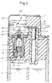
- the operating lever 7 is slid toward the windshield 32 forcibly as shown in Figure 4 and Figure 6.
- the sliding movement operates to rub the flint 5 against the sparking rasp 6, and thus emitting sparks adjacent the burner nozzle 3.
- the thruster 28 contacts the neck portion of the burner nozzle 3 to lower the burner nozzle 3, and the shutter 29 is moved, so that the opening member 31 is positioned at the upper portion of the nozzle 3, and thus the nozzle is opened.
- the inlet valve member 19 contacts tightly onto the inlet valve seat 20, whereby the measuring space including the fuel storing space 21 is isolated from the fuel reservoir 2.
- the bar 18 pushes up the outlet valve member 23 against the action of the spring 24 and the valve member 23 is separated from the outlet valve seat 17 to open the outlet valve.
- the outlet valve is opened as above, with reference to Figure 8, the fuel stored in the measuring space moves upward through the nozzle 3 to be delivered through the nozzle aperture 22, and finally the fuel is ignited by the sparks, forming a flame extending through the flame emerging aperture 33.
- the flame extinguishes itself because there is no further supply of fuel from the fuel reservoir 2. In other words, the flame is maintained only for a limited time during burning of the fixed quantity of fuel in the measuring space. After the consumption of the fuel, the flame automatically dies out.
- the power of the helical spring 27 drives the lever 7 into the original place, whereon the force on the burner nozzle 3 is also released.
- the burner nozzle 3 is elevated to its normal position by the spring 24 and the gas pressure exerted on the valve member 23 and the outlet valve closes.
- the inlet valve opens, whereon the measuring space again communicates with the fuel reservoir 2 to permit the fuel to flow through the aperture 11 to fill the measuring space ready for the next ignition.
- the closing member 30 of the shutter 29 As the closing member 30 of the shutter 29 is driven by the synchronous movement of the operating lever 7, it covers the nozzle aperture 22, and the flame stops its continuous burning, even if there is fuel remaining.
- the quantity of gas fuel is fixed at an amount necessary for a single burn. If the operating lever 7 should be unexpectedly released earlier than the time for the fixed quantity to burn, it may be feared that some undesirable burning is continued. Therefore, it is preferable to design the shutter 29 for the automatic extinguishment.
- the lighter of this embodiment is a normal disposable lighter equipped with a sparking wheel as the ignition mechanism and with a push down lever.
- a lighter body 101 having a reservoir 102 on its lower portion includes an ignition mechanism mounted on its top portion over the reservoir 102.
- the ignition mechanism comprises a burner valve 104 including a burner nozzle 103, a flint 105, a sparking wheel 106 and an operating lever 107 which operates the burner valve 104 and the wheel 106.
- a lighter body is produced of synthetic resin material, having the reservoir 102 on its lower portion and having a block body 108 for the ignition mechanism on its top portion, and the body 108 is tightly sealed against the reservoir 102.
- two pits 109, 110 are provided parallel to one another, both having open tops and closed bottoms.
- the first pit 109 is of larger diameter than the second pit 110, and the pit 109 is formed on one side of the block body 108 and communicates with the reservoir 102 via a small aperture 111.
- a burner valve body 112 is movable within the first pit 109.
- the burner valve body 112 is a cylindrical member having an open top and closed bottom.
- An O-ring 113 is on the lower and outer surface of the valve body 112, whereas the ring 113 tightly seals the gap produced between the inner surface of the first pit 109 and the outer surface of the burner valve body 112.
- a penetrating aperture 116 is provided on the central portion of a separation wall 115 closing the bottom of the burner valve body 112, a penetrating aperture 116 is provided, an outlet valve seat 124 being formed around the upper circumference of the aperture 116.
- a movable valve member 118 moves freely upwards and downwards in the burner valve body 112.
- the movable member 118 is produced from a compressible elastic sealing material such as rubber.
- This movable member 118 defines an outlet valve element 119 and an inlet valve element 120 below the outlet valve element 119, the elements 119, 120 being connected by a coupler 121 of small diameter.
- a bar 122 extends downward from the central portion of the inlet valve element 120, and the bar 122 passes through the penetrating aperture 116 to freely contact the inner bottom surface of the first pit 109.
- the burner nozzle 103 is screwed into the burner valve body 112 from the mouth, and these two parts 103,112 act as a single integral member.
- the burner nozzle 103 is cylindrical in shape, having a small nozzle aperture 123 provided on the top thereof and having an open bottom, and the outlet valve element 119 is arranged to contact and become detached from the outlet valve seat 124 which is formed on the inner bottom surface of the burner nozzle 103.
- the movable valve member 118 is normally pressurized downwards by a spring 114 located between the bottom surface of the burner nozzle 103 and the top surface of the inlet valve element 120.
- the integral member 123,112 urges the bar 122 into contact with the bottom surface of the first pit 109.
- the outlet valve element 119 contacts tightly onto the bottom surface of the outlet valve seat 124 to close the passage to the nozzle aperture 123, while the inlet valve element 120 is separated from the inlet valve seat 117 to permit fuel to flow into a fuel storing space 125 through the small aperture 111.
- the fuel storing space 125 is a measuring space to measure a fixed quantity of fuel, and only this fixed quantity is emitted through the nozzle aperture 123 when the valve is opened.
- a fuel flow regulating member 126 is also provided adjacent the nozzle aperture 123.
- the member 126 is made from porous material exactly same as the first embodiment, and the material only permits a fixed quantity of gas fuel to pass through.
- the burner nozzle 103 and the burner valve body 112 are driven upward.
- the elevation of the burner valve body 112 promotes the contact between the inlet valve element 120 and the inlet valve seat 117 to close the inlet valve.
- the movable valve member 118 moves down under the force of the spring 114.
- the outlet valve element 119 is separated from the outlet valve seat 124 to produce a space therebetween, opening the outlet valve. Then the fuel stored in the storing space 125 is permitted to flow through the nozzle aperture 123.
- the actual quantity of fuel permitted to be delivered is not equal to that present in the fuel storing space 125, and we define the space containing the actual quantity to be the measuring space, rather than the fuel storing space 125. This measuring space is largely dependent upon the size of the fuel storing space 125.
- a flint holder 127 of cylindrical shape is provided, a flint 105 being housed therein and forced constantly toward the upper end of the pit 110 by a flint spring 128.
- a sparking wheel 106 is located to rub against the flint 105.
- the operating lever 107 is mounted on the upper portion of the block body 108, and it is normally biased by a lever spring 129 to a standstill position as shown in Figure 10.
- the operating lever 107 In order to ignite a lighter, the operating lever 107 is forcibly pushed down and the sparking wheel 106 is rotated as shown in Figure 11. By this rotation, sparks are generated adjacent the burner nozzle 103. Movement of the operating lever 107 lifts the burner nozzle 103. This movement causes the inlet valve to close, isolating the measuring space including the fuel storing space 125 from the reservoir 102, while the same movement also opens the outlet valve. When the outlet valve is opened as above, with reference to Figure 11, the fuel stored in the measuring space starts to move upwards through the burner nozzle 103 and nozzle aperture 123, and finally the fuel is ignited by the sparks.
- the flame extinguishes itself because there is no further supply of fuel from the reservoir 102.
- the generated flame is maintained only for a limited time for the fixed quantity of fuel stored in the measuring space, and after the consumption of the fuel, the flame automatically dies out.
- the operating lever 107 After cigarette ignition, the operating lever 107 is released, and the power of the lever spring 129 drives the lever 107 into the original position, whereon the burner nozzle 103 is lowered to its normal position and the outlet valve closes. At the same time, the lowering of the burner nozzle 103 results in the inlet valve opening whereon the measuring space again communicates with the reservoir 102 to permit fuel to flow freely through the aperture 111 to fill the measuring space ready for the succeeding ignition.
Abstract
A pocket lighter is disclosed which comprises a measuring chamber (21, 125) an inlet valve (19, 20, 117, 120) and an outlet valve (17, 23, 119, 124), the inlet and outlet valves (19, 20, 117, 120, 17, 23, 119, 124) being arranged such that opening of the outlet valve (17, 23, 119, 124) permits fuel to flow from the measuring chamber (21, 125) resulting in the inlet valve (19, 20, 117, 120) being closed, and closing of the outlet valve (17, 23, 119, 124) results in the inlet valve (19, 20, 117, 120) being opened to permit fuel to flow into the measuring chamber (21, 125).
Description
- Pocket lighters, for example cigarette lighters commonly comprise a reservoir in which liquefied gas fuel is stored under pressure, the gas being ignited at a burner nozzle attached to an integral burner valve, in use. Ignition occurs when the fuel is permitted to flow beyond the open burner valve nozzle connected to the reservoir. In such lighters, the supply of fuel to the burner nozzle is only interrupted when the burner valve is closed. The continuous burning of fuel through failing to close the valve has often caused accidents, for example fires, burns and the like. There is concern that misuse of lighters by children may result in a large accident. In order to avoid these dangers, a new lighter has been developed in which only a fixed and limited quantity of fuel is permitted to flow out of the lighter during each use of the lighter, and once the fixed quantity is exhausted, the burning terminates, the supply of fuel being exhausted.
- The present invention has been developed in view of these situations.
- An object of this invention is to provide a lighter, wherein only a fixed and limited quantity of gas fuel is supplied for one ignition during valve opening. After the quantity is used up the lighter is automatically extinguished.
- According to the present invention there is provided a pocket lighter characterised by a measuring chamber an inlet valve and an outlet valve, the inlet and outlet valves being arranged such that opening of the outlet valve permitting fuel to flow from the measuring chamber results in the inlet valve being closed, and closing of the outlet valve results in the inlet valve being opened to permit fuel to flow into the measuring chamber.
- This invention operates as follows: when an operating lever is actuated, a burner nozzle and valve body descend together, closing the inlet valve and opening the outlet valve the reverse movement of the lever causing the inlet valve to open and the outlet valve to close. The measuring space is defined between the inlet and outlet valves, a fixed quantity of fuel being held in the measuring space, in use.
- During actuation of the operating lever, the burner nozzle and the valve body are pushed downward simultaneously. When the burner valve moves down, the valve member of the inlet valve contacts tightly onto the respective valve seat, closing the inlet valve. The valve member of the outlet valve is pushed upwards by a bar separating the member from the respective valve seat. Accordingly, gas fuel stored in the measuring space including a gas fuel storing space is emitted through a nozzle aperture and the fuel is ignited. As the inlet valve is closed, the supply of gas fuel from a reservoir to the burner nozzle is prevented, only the fixed quantity of fuel in the measuring space being permitted to flow to the nozzle. The exhaustion of the fuel automatically results in the flame of the lighter being extinguished.
- In an alternative embodiment, when an operating lever is actuated, a burner nozzle and valve body are both lifted resulting in the contact between the valve member of the outlet valve and a respective valve seat being released while the valve member of the inlet valve and a respective valve seat are brought into contact with one another, the fixed quantity of gas fuel being provided in the measuring space formed between the inlet and outlet valves.
- Such movement of the operating lever results in opening of the outlet valve and closing of the inlet valve, thus gas fuel stored in the measuring space including a gas fuel storing space is emitted through a nozzle aperture and the fuel is ignited. As the tight contact between the inlet valve member and inlet valve seat is maintained, the further supply of fuel from a reservoir is completely interrupted, and hence when the fixed quantity of fuel is exhausted, the flame is automatically extinguished.
- The invention will further be described, by way of example, with reference to the accompanying drawings, in which:-
- Figure 1 is a perspective view of a lighter of a first embodiment of the invention;
- Figure 2 is a perspective view of the lighter of Figure 1 when ignited;
- Figure 3 is an expanded sectional view of the lighter of Figure 1;
- Figure 4 is an expanded sectional view of the lighter of Figure 1, in use;
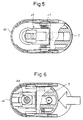
- Figure 5 is an enlarged transverse sectional view of the view of Figure 3;
- Figure 6 is an enlarged transverse sectional view of the view of Figure 4;
- Figure 7 is an exploded perspective view of main parts;
- Figure 8 shows the flow of gas fuel when the valve is open;
- Figure 9 is a longitudinal sectional view of a second embodiment of the present invention;
- Figure 10 is an enlarged fragmentary longitudinal sectional view of the embodiment of Figure 9 with the outlet valve closed; and
- Figure 11 is an enlarged fragmentary longitudinal sectional view of the embodiment of Figure 9 with the outlet valve open.
- Figure 1 ∼ Figure 8 show the first embodiment of the present invention. A disposable pocket lighter 1, has a
fuel reservoir 2 provided on its lower portion. On the upper portion of thelighter 1 above thereservoir 2, an ignition mechanism is mounted, comprising anoperating lever 7 operating aburner nozzle 3 of a burner valve 4 as well as asparking rasp 6 for rubbing against aflint 5. - Referring to Figure 3 ∼ Figure 7, the lighter is of oval cylindrical shape and is made of synthetic resin material, and comprises the
reservoir 2 on the lower portion thereof, ablock body 8 on the upper portion thereof for the ignition mechanism to be mounted upon, tightly sealed against thereservoir 2. Thus, thereservoir 2 is established. On theblock body 8, twopits 9, 10 are provided parallel to one another, both having open tops and closed bottoms. The first pit 9 is of larger diameter than thesecond pit 10, and the first pit 9 is positioned on the one side of theblock body 8 and communicates with thereservoir 2 via asmall aperture 11. Aburner valve body 12 is movable within the first pit 9. Theburner valve body 12 is a cylindrical member having an open top and a closed bottom. An O-ring 13 is provided on the lower and outer surface of thevalve body 12. Thering 13 tightly seals the gap formed by the inner surface of the first pit 9 and the outer surface of theburner valve body 12. Abinding ring 14 is screwed into the open end of the first pit 9 and prevents theburner valve body 12 from falling out of the first pit 9, in use. A penetratingaperture 16 is drilled on the central portion of a separation wall 15 closing the bottom of theburner valve body 12. Anoutlet valve seat 17 is formed around the upper circumference of theaperture 16. Abar 18 is provided at the centre of the inside of the bottom of the first pit 9, and is capable of moving freely into and out of theaperture 16. Aninlet valve member 19 is provided around the circumference of thebar 18, and thevalve member 19 is arranged to contact or become detached from aninlet valve seat 20 provided on the bottom of theburner valve body 12 according to the movement of thebody 12. The inner space of theburner valve body 12 between theinlet valve seat 20 and the separation wall 15 is of enlarged width, this space defining a gasfuel storing space 21. - The
burner nozzle 3 is forcibly inserted into theburner valve body 12 by caulking to form one integral part. Theburner nozzle 3 is a cylindrical member having anozzle aperture 22 provided in the upper portion thereof, and an opening receiving a movableoutlet valve member 23 arranged to contact or become detached from theoutlet valve seat 17. Theoutlet valve member 23 is normally forced downwards by aspring 24 provided in theburner nozzle 3, namely toward theoutlet valve seat 17 and is forcibly engaged with theseat 17. The material of theoutlet valve member 23 and theinlet valve member 19 is an elastic material like rubber. A fuelflow regulating member 34 is next to thenozzle aperture 22 in theburner nozzle 3. This regulatingmember 34 is made from porous material, such as sintered metal, sintered plastic, ceramics and so on, which permits a fixed quantity of gas fuel to pass through. Thismember 34 prevents the fuel stored in thefuel storing space 21 from being delivered suddenly. The sintered plastic is made of polyethylene, polyacetal or the like after grains of these plastics materials have been sintered by heat or ultrasonic processes. - When the
burner nozzle 3 is pushed downwards, theburner valve body 12 also descends. By this descent, theinlet valve seat 20 located in the lower portion of theburner valve body 12 contacts tightly onto theinlet valve member 19 to close the inlet valve. Thebar 18 moves through the penetratingaperture 16 asburner valve body 12 descends, and pushes theoutlet valve member 23 upwards, whereby theoutlet valve member 23 is separated from theoutlet valve seat 17 to open the outlet valve. Thus, the fuel in thefuel storing space 21 is delivered through thenozzle aperture 22. As the inlet valve is closed, no fuel supply is permitted into thefuel storing space 21. Therefore only the fixed and limited amount of fuel remaining in thespace 21 is permitted to be delivered. The actual quantity of gas fuel in the space defined between the inlet and outlet valves, and accordingly the actual quantity is not limited to the amount in thefuel storing space 21. In this specification, therefore, we define the space containing the actual quantity to be delivered as the measuring space. This measuring space is mainly dependent upon the size of thefuel storing space 21. - The
second pit 10 is parallel to the first pit 9. Aflint holder 25 of cylindrical shape is provided in thepit 10, and aflint 5 is provided in the holder and is forced constantly outwards by a flint spring 26. A sparkingrasp 6 is located in direct contact with theflint 5. In the present embodiment, the sparkingrasp 6 is in the form of a flat plate which is different from the normal style of a wheel. The required sparking for ignition is generated by the horizontal sliding rubbing motion between theflint 5 and therasp 6. - The operating
lever 7 is provided on the upper portion of theblock body 8 and is capable of free sliding movement in the horizontal direction, and it is normally biased by ahelical spring 27 to a standstill position as shown in Figure 3. On the lower surface of the operatinglever 7 is anozzle thruster 28 having a circular arc-shaped lower surface which is integral with the body. The sparkingrasp 6 is adhered to the rear bottom surface of thelever 7. Ashutter 29 is also located horizontally on the front portion of thelever 7 just above thethruster 28. Theshutter 29 has two members, one being a closingmember 30 and the other an openingmember 31, and when the sliding movement of the operatinglever 7 occurs, the closingmember 30 leaves the upper portion of theburner nozzle 3 and is replaced by the openingmember 31, the upper portion of theburner nozzle 3 being opened. Awindshield 32 is provided which covers theburner nozzle 3, theshutter 29, one portion of the operatinglever 7 and theblock body 8. Thiswindshield 32 is mounted on thelighter body 1. Aflame emerging aperture 33 is also directly above thenozzle aperture 22 in theburner nozzle 3. A stopper mechanism is recommended for the sliding action of the operatinglever 7, so that random and sudden ignitions may be avoided. This stopper reduces danger caused by the child misuse. - In order to ignite the lighter, the operating
lever 7 is slid toward thewindshield 32 forcibly as shown in Figure 4 and Figure 6. The sliding movement operates to rub theflint 5 against the sparkingrasp 6, and thus emitting sparks adjacent theburner nozzle 3. By this same operation, thethruster 28 contacts the neck portion of theburner nozzle 3 to lower theburner nozzle 3, and theshutter 29 is moved, so that the openingmember 31 is positioned at the upper portion of thenozzle 3, and thus the nozzle is opened. At the end of the descent of theburner nozzle 3, theinlet valve member 19 contacts tightly onto theinlet valve seat 20, whereby the measuring space including thefuel storing space 21 is isolated from thefuel reservoir 2. Thebar 18 pushes up theoutlet valve member 23 against the action of thespring 24 and thevalve member 23 is separated from theoutlet valve seat 17 to open the outlet valve. When the outlet valve is opened as above, with reference to Figure 8, the fuel stored in the measuring space moves upward through thenozzle 3 to be delivered through thenozzle aperture 22, and finally the fuel is ignited by the sparks, forming a flame extending through theflame emerging aperture 33. When the fuel stored in the measuring space is exhausted, the flame extinguishes itself because there is no further supply of fuel from thefuel reservoir 2. In other words, the flame is maintained only for a limited time during burning of the fixed quantity of fuel in the measuring space. After the consumption of the fuel, the flame automatically dies out. - After cigarette ignition, when the operating
lever 7 is released, the power of thehelical spring 27 drives thelever 7 into the original place, whereon the force on theburner nozzle 3 is also released. Next, theburner nozzle 3 is elevated to its normal position by thespring 24 and the gas pressure exerted on thevalve member 23 and the outlet valve closes. At the same time, by the elevation of theburner nozzle 3, the inlet valve opens, whereon the measuring space again communicates with thefuel reservoir 2 to permit the fuel to flow through theaperture 11 to fill the measuring space ready for the next ignition. - As the closing
member 30 of theshutter 29 is driven by the synchronous movement of the operatinglever 7, it covers thenozzle aperture 22, and the flame stops its continuous burning, even if there is fuel remaining. In this embodiment, the quantity of gas fuel is fixed at an amount necessary for a single burn. If the operatinglever 7 should be unexpectedly released earlier than the time for the fixed quantity to burn, it may be feared that some undesirable burning is continued. Therefore, it is preferable to design theshutter 29 for the automatic extinguishment. - The second example of the invention is described with reference to Figures 9 to 11. The lighter of this embodiment is a normal disposable lighter equipped with a sparking wheel as the ignition mechanism and with a push down lever.
- A
lighter body 101, having areservoir 102 on its lower portion includes an ignition mechanism mounted on its top portion over thereservoir 102. The ignition mechanism comprises aburner valve 104 including aburner nozzle 103, aflint 105, a sparkingwheel 106 and anoperating lever 107 which operates theburner valve 104 and thewheel 106. - With reference to Figure 9 ∼ Figure 11, a lighter body is produced of synthetic resin material, having the
reservoir 102 on its lower portion and having ablock body 108 for the ignition mechanism on its top portion, and thebody 108 is tightly sealed against thereservoir 102. On theblock body 108, twopits first pit 109 is of larger diameter than thesecond pit 110, and thepit 109 is formed on one side of theblock body 108 and communicates with thereservoir 102 via a small aperture 111. Aburner valve body 112 is movable within thefirst pit 109. Theburner valve body 112 is a cylindrical member having an open top and closed bottom. An O-ring 113 is on the lower and outer surface of thevalve body 112, whereas thering 113 tightly seals the gap produced between the inner surface of thefirst pit 109 and the outer surface of theburner valve body 112. On the central portion of aseparation wall 115 closing the bottom of theburner valve body 112, a penetratingaperture 116 is provided, anoutlet valve seat 124 being formed around the upper circumference of theaperture 116. Amovable valve member 118 moves freely upwards and downwards in theburner valve body 112. Themovable member 118 is produced from a compressible elastic sealing material such as rubber. Thismovable member 118 defines anoutlet valve element 119 and aninlet valve element 120 below theoutlet valve element 119, theelements coupler 121 of small diameter. Abar 122 extends downward from the central portion of theinlet valve element 120, and thebar 122 passes through the penetratingaperture 116 to freely contact the inner bottom surface of thefirst pit 109. - The
burner nozzle 103 is screwed into theburner valve body 112 from the mouth, and these two parts 103,112 act as a single integral member. Theburner nozzle 103 is cylindrical in shape, having asmall nozzle aperture 123 provided on the top thereof and having an open bottom, and theoutlet valve element 119 is arranged to contact and become detached from theoutlet valve seat 124 which is formed on the inner bottom surface of theburner nozzle 103. Themovable valve member 118 is normally pressurized downwards by aspring 114 located between the bottom surface of theburner nozzle 103 and the top surface of theinlet valve element 120. The integral member 123,112 urges thebar 122 into contact with the bottom surface of thefirst pit 109. By this urging, theoutlet valve element 119 contacts tightly onto the bottom surface of theoutlet valve seat 124 to close the passage to thenozzle aperture 123, while theinlet valve element 120 is separated from theinlet valve seat 117 to permit fuel to flow into afuel storing space 125 through the small aperture 111. Thefuel storing space 125 is a measuring space to measure a fixed quantity of fuel, and only this fixed quantity is emitted through thenozzle aperture 123 when the valve is opened. A fuelflow regulating member 126 is also provided adjacent thenozzle aperture 123. Themember 126 is made from porous material exactly same as the first embodiment, and the material only permits a fixed quantity of gas fuel to pass through. - When the operating
lever 107 is pushed down, theburner nozzle 103 and theburner valve body 112 are driven upward. The elevation of theburner valve body 112 promotes the contact between theinlet valve element 120 and theinlet valve seat 117 to close the inlet valve. Moving in the opposite direction to the upward movement of theburner valve body 112, themovable valve member 118 moves down under the force of thespring 114. As shown in Figure 11, theoutlet valve element 119 is separated from theoutlet valve seat 124 to produce a space therebetween, opening the outlet valve. Then the fuel stored in the storingspace 125 is permitted to flow through thenozzle aperture 123. The tight contact between theinlet valve element 120 and theinlet valve seat 117 prevents the flow of fuel from thereservoir 102 into thefuel storing space 125, and therefore only the fixed quantity of fuel measured by the measuring space including thefuel storing space 125 is permitted to flow through thenozzle aperture 123. The actual quantity of fuel permitted to be delivered is not equal to that present in thefuel storing space 125, and we define the space containing the actual quantity to be the measuring space, rather than thefuel storing space 125. This measuring space is largely dependent upon the size of thefuel storing space 125. - In the
second pit 110 parallel to thefirst pit 109, aflint holder 127 of cylindrical shape is provided, aflint 105 being housed therein and forced constantly toward the upper end of thepit 110 by aflint spring 128. On the upper portion of theflint holder 127, a sparkingwheel 106 is located to rub against theflint 105. - The operating
lever 107 is mounted on the upper portion of theblock body 108, and it is normally biased by alever spring 129 to a standstill position as shown in Figure 10. - In order to ignite a lighter, the operating
lever 107 is forcibly pushed down and the sparkingwheel 106 is rotated as shown in Figure 11. By this rotation, sparks are generated adjacent theburner nozzle 103. Movement of the operatinglever 107 lifts theburner nozzle 103. This movement causes the inlet valve to close, isolating the measuring space including thefuel storing space 125 from thereservoir 102, while the same movement also opens the outlet valve. When the outlet valve is opened as above, with reference to Figure 11, the fuel stored in the measuring space starts to move upwards through theburner nozzle 103 andnozzle aperture 123, and finally the fuel is ignited by the sparks. When the fuel stored in the measuring space is exhausted, the flame extinguishes itself because there is no further supply of fuel from thereservoir 102. In other words, the generated flame is maintained only for a limited time for the fixed quantity of fuel stored in the measuring space, and after the consumption of the fuel, the flame automatically dies out. - After cigarette ignition, the operating
lever 107 is released, and the power of thelever spring 129 drives thelever 107 into the original position, whereon theburner nozzle 103 is lowered to its normal position and the outlet valve closes. At the same time, the lowering of theburner nozzle 103 results in the inlet valve opening whereon the measuring space again communicates with thereservoir 102 to permit fuel to flow freely through the aperture 111 to fill the measuring space ready for the succeeding ignition. - While the preferred embodiments of the present invention have been described, such description is for the purpose of illustration only and it is to be understood by those skilled in the art that changes and variations using refillable lighters or other different ignition mechanisms may be made without departing from the scope of the invention as defined by the following claims.
Claims (10)
- A pocket lighter characterised by a measuring chamber (21, 125) an inlet valve (19, 20, 117, 120) and an outlet valve (17, 23, 119, 124), the inlet and outlet valves (19, 20, 117, 120, 17, 23, 119, 124) being arranged such that opening of the outlet valve (17, 23, 119, 124) permitting fuel to flow from the measuring chamber (21, 125) results in the inlet valve (19, 20, 117, 120) being closed, and closing of the outlet valve (17, 23, 119, 124) results in the inlet valve (19, 20,117,120) being opened to permit fuel to flow into the measuring chamber (21, 125).
- A pocket lighter as claimed in Claim 1, characterised by an operating lever (7, 107) for use in operating the pocket lighter.
- A pocket lighter as claimed in Claim 1 or Claim 2, characterised by a movable valve body (12, 112) defining at least part of each of the inlet and outlet valves (19, 20, 117, 120, 17, 23, 119, 124).
- A pocket lighter as claimed in Claim 3, characterised in that the valve body (12, 112) includes a burner nozzle (3, 103).
- A pocket lighter as claimed in Claim 3 or Claim 4, characterised in that downward movement of the valve body (12) results in opening of the outlet valve (17, 23) and closing of the inlet valve (19, 20).
- A pocket lighter as claimed in Claim 3 or Claim 4, characterised in that upward movement of the valve body (112) results in opening of the outlet valve (119, 124) and closing of the inlet valve (117, 120).
- A pocket lighter as claimed in any one of Claims 4 to 6, characterised by an aperture (22) in said burner nozzle (3), and a shutter (29) mounted on an upper portion of the burner nozzle (3) for stopping emission of gas fuel from the aperture (22), said shutter (29) being adapted to move freely from a closing position to an opening position in response to operating lever (7) movement.
- A pocket lighter as claimed in any one of Claims 2 to 7, characterised by a lighter body (1), wherein the operating lever (7) is slidably movable in a generally horizontal direction, in use, with respect to said lighter body (1), and wherein the operating lever (7) has a thruster (28) for forcing the valve body (12) to descend.
- A pocket lighter as claimed in Claim 8, characterised by a sparking rasp (6) in plate form which is provided on the operating lever (7), said rasp (6) extending in the sliding direction of the lever (7), and wherein the rasp (6) moves substantially perpendicularly to a flint (5) for producing sparks.
- A pocket lighter as claimed in any one of the preceding claims, characterised by a porous flow regulating member (34, 126) for regulating flow of gas fuel.
Applications Claiming Priority (4)
| Application Number | Priority Date | Filing Date | Title |
|---|---|---|---|
| JP33927693A JPH07158852A (en) | 1993-12-03 | 1993-12-03 | Pocket lighter |
| JP339276/93 | 1993-12-03 | ||
| JP347456/93 | 1993-12-24 | ||
| JP34745693A JPH07190356A (en) | 1993-12-24 | 1993-12-24 | Pocket lighter |
Publications (2)
| Publication Number | Publication Date |
|---|---|
| EP0656510A2 true EP0656510A2 (en) | 1995-06-07 |
| EP0656510A3 EP0656510A3 (en) | 1996-03-20 |
Family
ID=26576376
Family Applications (1)
| Application Number | Title | Priority Date | Filing Date |
|---|---|---|---|
| EP94308718A Withdrawn EP0656510A3 (en) | 1993-12-03 | 1994-11-25 | Pocket lighter. |
Country Status (3)
| Country | Link |
|---|---|
| EP (1) | EP0656510A3 (en) |
| KR (1) | KR950019371A (en) |
| CN (1) | CN1107215A (en) |
Families Citing this family (2)
| Publication number | Priority date | Publication date | Assignee | Title |
|---|---|---|---|---|
| KR20050036710A (en) * | 2003-10-15 | 2005-04-20 | 이기철 | Gas lighter |
| CN112443856B (en) * | 2020-11-04 | 2022-09-13 | 浙江特灵轻工集团有限公司 | Portable rotary lighter |
Citations (4)
| Publication number | Priority date | Publication date | Assignee | Title |
|---|---|---|---|---|
| FR2149497A1 (en) * | 1971-08-16 | 1973-03-30 | Butane Match Ag | |
| US3820941A (en) * | 1972-12-22 | 1974-06-28 | Int Fire Tool Corp | Lighter construction |
| GB1531138A (en) * | 1975-03-18 | 1978-11-01 | Hadson Trading Co Ltd | Gas fueled lighter |
| EP0029791A1 (en) * | 1979-11-22 | 1981-06-03 | YVES SAINT-LAURENT NONESUCH Société à Responsabilité limitée dite: | Safety gas lighter |
-
1994
- 1994-11-25 EP EP94308718A patent/EP0656510A3/en not_active Withdrawn
- 1994-12-02 KR KR1019940032587A patent/KR950019371A/en not_active Application Discontinuation
- 1994-12-03 CN CN94119887A patent/CN1107215A/en active Pending
Patent Citations (4)
| Publication number | Priority date | Publication date | Assignee | Title |
|---|---|---|---|---|
| FR2149497A1 (en) * | 1971-08-16 | 1973-03-30 | Butane Match Ag | |
| US3820941A (en) * | 1972-12-22 | 1974-06-28 | Int Fire Tool Corp | Lighter construction |
| GB1531138A (en) * | 1975-03-18 | 1978-11-01 | Hadson Trading Co Ltd | Gas fueled lighter |
| EP0029791A1 (en) * | 1979-11-22 | 1981-06-03 | YVES SAINT-LAURENT NONESUCH Société à Responsabilité limitée dite: | Safety gas lighter |
Also Published As
| Publication number | Publication date |
|---|---|
| EP0656510A3 (en) | 1996-03-20 |
| KR950019371A (en) | 1995-07-22 |
| CN1107215A (en) | 1995-08-23 |
Similar Documents
| Publication | Publication Date | Title |
|---|---|---|
| US3898031A (en) | Gas fueled safety lighter | |
| US5368473A (en) | Gas lighter with safety device | |
| EP0137503A1 (en) | Foldable safety lighter | |
| US3092988A (en) | Disposable lighter construction | |
| US2727376A (en) | Pressurized pyrophoric gas lighter | |
| US6722877B2 (en) | Utility lighter with disabling mechanism | |
| US7335017B2 (en) | Lighter with flint igniter | |
| EP0656510A2 (en) | Pocket lighter | |
| US5472338A (en) | Cigarette lighter safety with thumb locking mechanism | |
| KR200202998Y1 (en) | Ignition-ignited gas lighter with ignition arrest function | |
| US20050181320A1 (en) | Flint ignited premixed lighter and method of operating a lighter | |
| US4144018A (en) | Cigarette lighter using hypergolic fuel component | |
| US2672038A (en) | Gas lighter valve | |
| US3820941A (en) | Lighter construction | |
| JPH0630663U (en) | Cigarette type gas lighter | |
| US5921768A (en) | Flame torch | |
| EP0660045A2 (en) | Pocket lighter | |
| US6186774B1 (en) | Modular butane lighter | |
| US3938942A (en) | Pyrophoric gas lighter | |
| US3253430A (en) | Lighter assembly | |
| US6773258B1 (en) | Windproof lighter | |
| US2708842A (en) | Gas burning cigarette lighters | |
| US4415329A (en) | Wax-encased butane safety candle | |
| US4395227A (en) | Flame thrower attachment | |
| US3556703A (en) | Small lighter |
Legal Events
| Date | Code | Title | Description |
|---|---|---|---|
| PUAI | Public reference made under article 153(3) epc to a published international application that has entered the european phase |
Free format text: ORIGINAL CODE: 0009012 |
|
| AK | Designated contracting states |
Kind code of ref document: A2 Designated state(s): DE FR GB |
|
| PUAL | Search report despatched |
Free format text: ORIGINAL CODE: 0009013 |
|
| AK | Designated contracting states |
Kind code of ref document: A3 Designated state(s): DE FR GB |
|
| STAA | Information on the status of an ep patent application or granted ep patent |
Free format text: STATUS: THE APPLICATION IS DEEMED TO BE WITHDRAWN |
|
| 18D | Application deemed to be withdrawn |
Effective date: 19960921 |