EP0656494A1 - Elastomeric seal - Google Patents
Elastomeric seal Download PDFInfo
- Publication number
- EP0656494A1 EP0656494A1 EP93119321A EP93119321A EP0656494A1 EP 0656494 A1 EP0656494 A1 EP 0656494A1 EP 93119321 A EP93119321 A EP 93119321A EP 93119321 A EP93119321 A EP 93119321A EP 0656494 A1 EP0656494 A1 EP 0656494A1
- Authority
- EP
- European Patent Office
- Prior art keywords
- seal
- concave
- annular space
- seal according
- convex
- Prior art date
- Legal status (The legal status is an assumption and is not a legal conclusion. Google has not performed a legal analysis and makes no representation as to the accuracy of the status listed.)
- Withdrawn
Links
- 230000009477 glass transition Effects 0.000 claims abstract description 10
- 229920001971 elastomer Polymers 0.000 claims description 25
- 239000000806 elastomer Substances 0.000 claims description 25
- BQCIDUSAKPWEOX-UHFFFAOYSA-N 1,1-Difluoroethene Chemical compound FC(F)=C BQCIDUSAKPWEOX-UHFFFAOYSA-N 0.000 claims description 4
- -1 perfluorinated alkyl vinyl ethers Chemical class 0.000 claims description 4
- 230000003068 static effect Effects 0.000 claims description 4
- PYVHTIWHNXTVPF-UHFFFAOYSA-N F.F.F.F.C=C Chemical compound F.F.F.F.C=C PYVHTIWHNXTVPF-UHFFFAOYSA-N 0.000 claims description 2
- HCDGVLDPFQMKDK-UHFFFAOYSA-N hexafluoropropylene Chemical compound FC(F)=C(F)C(F)(F)F HCDGVLDPFQMKDK-UHFFFAOYSA-N 0.000 claims description 2
- 229920000098 polyolefin Polymers 0.000 claims description 2
- 239000012530 fluid Substances 0.000 description 9
- 238000007789 sealing Methods 0.000 description 7
- 238000005452 bending Methods 0.000 description 4
- 239000000463 material Substances 0.000 description 4
- 229920002449 FKM Polymers 0.000 description 3
- 229920006169 Perfluoroelastomer Polymers 0.000 description 2
- 239000004743 Polypropylene Substances 0.000 description 2
- 230000000694 effects Effects 0.000 description 2
- 239000000446 fuel Substances 0.000 description 2
- 238000000034 method Methods 0.000 description 2
- 230000000704 physical effect Effects 0.000 description 2
- 229920001155 polypropylene Polymers 0.000 description 2
- 230000008569 process Effects 0.000 description 2
- 230000009467 reduction Effects 0.000 description 2
- GWTYBAOENKSFAY-UHFFFAOYSA-N 1,1,1,2,2-pentafluoro-2-(1,2,2-trifluoroethenoxy)ethane Chemical compound FC(F)=C(F)OC(F)(F)C(F)(F)F GWTYBAOENKSFAY-UHFFFAOYSA-N 0.000 description 1
- 238000013459 approach Methods 0.000 description 1
- 230000008901 benefit Effects 0.000 description 1
- 230000015572 biosynthetic process Effects 0.000 description 1
- 230000008859 change Effects 0.000 description 1
- 239000013536 elastomeric material Substances 0.000 description 1
- FJKIXWOMBXYWOQ-UHFFFAOYSA-N ethenoxyethane Chemical class CCOC=C FJKIXWOMBXYWOQ-UHFFFAOYSA-N 0.000 description 1
- 230000002706 hydrostatic effect Effects 0.000 description 1
- 239000004615 ingredient Substances 0.000 description 1
- 238000004519 manufacturing process Methods 0.000 description 1
- 125000002496 methyl group Chemical group [H]C([H])([H])* 0.000 description 1
- 230000004048 modification Effects 0.000 description 1
- 238000012986 modification Methods 0.000 description 1
- 238000000465 moulding Methods 0.000 description 1
- 230000004044 response Effects 0.000 description 1
- 239000007787 solid Substances 0.000 description 1
- 230000036962 time dependent Effects 0.000 description 1
Images
Classifications
-
- F—MECHANICAL ENGINEERING; LIGHTING; HEATING; WEAPONS; BLASTING
- F16—ENGINEERING ELEMENTS AND UNITS; GENERAL MEASURES FOR PRODUCING AND MAINTAINING EFFECTIVE FUNCTIONING OF MACHINES OR INSTALLATIONS; THERMAL INSULATION IN GENERAL
- F16J—PISTONS; CYLINDERS; SEALINGS
- F16J15/00—Sealings
- F16J15/02—Sealings between relatively-stationary surfaces
- F16J15/021—Sealings between relatively-stationary surfaces with elastic packing
- F16J15/022—Sealings between relatively-stationary surfaces with elastic packing characterised by structure or material
- F16J15/024—Sealings between relatively-stationary surfaces with elastic packing characterised by structure or material the packing being locally weakened in order to increase elasticity
- F16J15/025—Sealings between relatively-stationary surfaces with elastic packing characterised by structure or material the packing being locally weakened in order to increase elasticity and with at least one flexible lip
-
- F—MECHANICAL ENGINEERING; LIGHTING; HEATING; WEAPONS; BLASTING
- F16—ENGINEERING ELEMENTS AND UNITS; GENERAL MEASURES FOR PRODUCING AND MAINTAINING EFFECTIVE FUNCTIONING OF MACHINES OR INSTALLATIONS; THERMAL INSULATION IN GENERAL
- F16L—PIPES; JOINTS OR FITTINGS FOR PIPES; SUPPORTS FOR PIPES, CABLES OR PROTECTIVE TUBING; MEANS FOR THERMAL INSULATION IN GENERAL
- F16L17/00—Joints with packing adapted to sealing by fluid pressure
- F16L17/06—Joints with packing adapted to sealing by fluid pressure with sealing rings arranged between the end surfaces of the pipes or flanges or arranged in recesses in the pipe ends or flanges
Definitions
- the present invention is directed to an elastomeric seal, more particularly to an elastomeric seal having an asymmetrical cross-section, and its use at a temperature near or below its glass transition point to form a seal, particularly, to seal an annular space.
- Elastomeric seals particularly those suitable for sealing annular spaces, typically have axial symmetry, such as, e.g. an "O"-ring. These seals are useful for various end uses, including in fuel injector applications for automobiles, mechanical seals and in virtually all instances where faces or shafts and housing need to be sealed.
- Certain elastomeric seals having asymmetrical cross-sections are also known (cf. DDR Patent 253 283 B1). Such seals are adapted for special applications, such as for sealing axially displaceable opposing components.
- the seals known heretofore are not suitable for functioning at temperatures near or below the glass transition point (Tg) of the elastomer. At such temperatures, various physical properties of the elastomeric material change, which lead to failure of the seal at such temperatures.
- Tg glass transition point
- Elastomers are also virtually incompressible and respond like highly viscous incompressible fluids when deformed. This trait of incompressibility makes solid elastomeric seals self-energizing, a feature that is utilized in "O"-rings and other torroidal seals against leakage at elevated pressures. The hydrostatic fluid pressure is transmitted through the seal in such a way that increasing the pressure of the fluid being sealed will also increase the sealing force applied by the seal on the sealing surfaces.
- a further advantage of the invention is that the seal may be made from any of the known elastomer materials, thereby avoiding the need to develop new, high cost elastomers having lower Tg values.
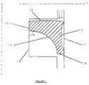
- Figure 1 provides a cross-sectional view of an annular space that is sealed by a seal according to the present invention.
- the seal is so designed to have an asymmetrical cross-section which allows control of shrinkage to create a bending moment within the seal, which opposes the negative effects of volumetric shrinkage of the elastomer material.
- the present invention provides an elastomeric seal adapted for use at a temperature near or below its glass transition point characterised in that it has a cross section forming a surface having at least three sides, two of which are concave and one of which is convex.
- Elastomer means any material which stretch under tension, have a high tensile strength, retract rapidly, and recover their original dimensions substantially fully. Suitable types of elastomers for the manufacture of seals are known to those skilled in the art, and particular such elastomers will be chosen according to the particular end-use application of the seal.
- Particularly preferred elastomers according to the invention are those containing two or more of the following repeating units: vinylidene fluoride (VF2), propylene hexafluoride (HFP), ethylene tetrafluoride (TFE), perfluorinated alkyl vinyl ethers (e.g. perfluorinated methyl or ethyl vinyl ethers (PMVE, PEVE)), and polyolefins (e.g. polypropylene (PP)).
- VF2 vinylidene fluoride
- HFP propylene hexafluoride
- TFE ethylene tetrafluoride
- PMVE, PEVE perfluorinated alkyl vinyl ethers
- PP polyolefins
- Suitable such elastomers are commercially available from the DuPont Company under the names VITON (an elastomer containing the repeating units VF2, HFP and TFE, also commonly known as an "FKM” type elastomer); and KALREZ and ZALAK (elastomers containing repeating units of perfluorinated alkyl vinyl ethers, also commonly known as "FFKM” type elastomers).
- a temperature "near or below" its glass transition point means a temperature where the elastomer ceases to behave as a highly viscous incompressible fluid and begins to have an increased modulus, creating a bending moment within the seal when a force is applied.
- Such temperature will vary depending upon the particular elastomer material and ingredients with which it is compounded.
- the glass transition point is typically between about +5 to -30 °C.
- Seals according to the invention will typically have axial symmetry since they are particularly adapted for providing a seal in an annular space.
- the symmetry may be about one of several axes marked "X" and "Y” in Figure 1.
- Annular space in this context, means the region defined between two concentric cylinders.
- Static application means an application that does not require movement of the seal with respect to the annular space. Such applications include the aforementioned automobile fuel injectors, mechanical seals and instances where faces or shafts and housing need to be sealed.
- the asymmetrical shape of a cross section of the seal according to the invention enables the glass transition point properties of the seal to be used advantageously to maintain a seal where conventionally shaped seals will fail.
- the shape of the seal having two concave sides and one convex side, enables a bending moment to be created in the seal which serves to keep the seal firmly in contact with the two surfaces that define the annular space.
- the shape of other sides of the seal if any, is not critical. The other sides may be flat, concave or convex, although preferably are substantially flat.
- the cross section forms a surface comprising at least five sides: (with reference to Figure 1) a first concave side (1.1), a convex side (1.3) adjacent thereto, a third side (1.2) adjacent to the convex side (1.3), a second concave side (1.4) adjacent to the third side (1.2) and a fifth side (1.5) joining the first and second concave sides (1.1, 1.4).
- the length ratio of the first concave side (1.1) to the third side (1.2) is preferably from 5 to 9, more preferably about 6 to 8, most preferably about 7,
- the length ratio of the convex side (1.3) to the fifth side (1.5) is preferably from 6 to 8, more preferably about 7
- the angle ( ⁇ ) formed between the tangent to the third side and the tangent to the second concave side at the point of intersection of the third side and second concave side is preferably from 45° to 90°, more preferably about 50-60°.
- Seals according to the invention can be made using conventional moulding processes, and as such, these processes are not described herein in detail.
- seals according to the invention are employed in applications heretofore known, albeit at temperatures where known seals fail.
- a seal according to the invention is positioned within the annular space to be sealed such that the first concave side (1.1) abuts one surface (1.6) defining the annular space and the third side (1.2) abuts the other surface (1.7) defining the annular space.
- a fluid, whose flow direction is indicated by the arrows in Figure 1 contacts, at least initially, convex side (1.3) of the seal.
- the force the surfaces of the annular space apply to the seal create a bending moment in the seal whereby at least part of, and advantageously as much of the first concave side (1.1) is kept firmly in contact with the surface (1.7) of the annular space to prevent passage of any fluid through the annular space.
Landscapes
- Engineering & Computer Science (AREA)
- General Engineering & Computer Science (AREA)
- Mechanical Engineering (AREA)
- Physics & Mathematics (AREA)
- Fluid Mechanics (AREA)
- Gasket Seals (AREA)
- Sealing Material Composition (AREA)
- Pyrane Compounds (AREA)
- Heterocyclic Carbon Compounds Containing A Hetero Ring Having Oxygen Or Sulfur (AREA)
Priority Applications (4)
| Application Number | Priority Date | Filing Date | Title |
|---|---|---|---|
| EP93119321A EP0656494A1 (en) | 1993-12-01 | 1993-12-01 | Elastomeric seal |
| PCT/US1994/013195 WO1995015452A1 (en) | 1993-12-01 | 1994-11-22 | Elastomeric seal |
| EP95904070A EP0731887A1 (en) | 1993-12-01 | 1994-11-22 | Elastomeric seal |
| JP7515638A JPH09506411A (ja) | 1993-12-01 | 1994-11-22 | 弾性シール |
Applications Claiming Priority (1)
| Application Number | Priority Date | Filing Date | Title |
|---|---|---|---|
| EP93119321A EP0656494A1 (en) | 1993-12-01 | 1993-12-01 | Elastomeric seal |
Publications (1)
| Publication Number | Publication Date |
|---|---|
| EP0656494A1 true EP0656494A1 (en) | 1995-06-07 |
Family
ID=8213456
Family Applications (2)
| Application Number | Title | Priority Date | Filing Date |
|---|---|---|---|
| EP93119321A Withdrawn EP0656494A1 (en) | 1993-12-01 | 1993-12-01 | Elastomeric seal |
| EP95904070A Withdrawn EP0731887A1 (en) | 1993-12-01 | 1994-11-22 | Elastomeric seal |
Family Applications After (1)
| Application Number | Title | Priority Date | Filing Date |
|---|---|---|---|
| EP95904070A Withdrawn EP0731887A1 (en) | 1993-12-01 | 1994-11-22 | Elastomeric seal |
Country Status (3)
| Country | Link |
|---|---|
| EP (2) | EP0656494A1 (OSRAM) |
| JP (1) | JPH09506411A (OSRAM) |
| WO (1) | WO1995015452A1 (OSRAM) |
Cited By (1)
| Publication number | Priority date | Publication date | Assignee | Title |
|---|---|---|---|---|
| WO2005054725A1 (de) * | 2003-12-05 | 2005-06-16 | Siemens Aktiengesellschaft | Vorrichtung, verfahren zum herstellen der vorrichtung, kammervorrichtung und übertragervorrichtung |
Families Citing this family (1)
| Publication number | Priority date | Publication date | Assignee | Title |
|---|---|---|---|---|
| DE4413863C2 (de) * | 1994-04-21 | 1996-03-28 | Parker Praedifa Gmbh | Dichtungsanordnung für Einspritzventile an Kraftstoffzuleitungen |
Citations (1)
| Publication number | Priority date | Publication date | Assignee | Title |
|---|---|---|---|---|
| US4625978A (en) * | 1985-05-20 | 1986-12-02 | Parker Hannifin Corporation | Low temperature seal |
Family Cites Families (2)
| Publication number | Priority date | Publication date | Assignee | Title |
|---|---|---|---|---|
| US4560174A (en) * | 1983-12-02 | 1985-12-24 | Berco S.P.A. | Multi lip seal |
| ATE127204T1 (de) * | 1991-07-05 | 1995-09-15 | Dixon Resine Spa | Ringförmige dichtung. |
-
1993
- 1993-12-01 EP EP93119321A patent/EP0656494A1/en not_active Withdrawn
-
1994
- 1994-11-22 EP EP95904070A patent/EP0731887A1/en not_active Withdrawn
- 1994-11-22 JP JP7515638A patent/JPH09506411A/ja active Pending
- 1994-11-22 WO PCT/US1994/013195 patent/WO1995015452A1/en not_active Ceased
Patent Citations (1)
| Publication number | Priority date | Publication date | Assignee | Title |
|---|---|---|---|---|
| US4625978A (en) * | 1985-05-20 | 1986-12-02 | Parker Hannifin Corporation | Low temperature seal |
Cited By (2)
| Publication number | Priority date | Publication date | Assignee | Title |
|---|---|---|---|---|
| WO2005054725A1 (de) * | 2003-12-05 | 2005-06-16 | Siemens Aktiengesellschaft | Vorrichtung, verfahren zum herstellen der vorrichtung, kammervorrichtung und übertragervorrichtung |
| US7726625B2 (en) | 2003-12-05 | 2010-06-01 | Continental Automotive Gmbh | Device, method for producing the device, chamber device and transfer device |
Also Published As
| Publication number | Publication date |
|---|---|
| EP0731887A1 (en) | 1996-09-18 |
| JPH09506411A (ja) | 1997-06-24 |
| EP0731887A4 (OSRAM) | 1996-10-16 |
| WO1995015452A1 (en) | 1995-06-08 |
Similar Documents
| Publication | Publication Date | Title |
|---|---|---|
| JP2607779Y2 (ja) | パッキン包含組立体 | |
| US6814358B2 (en) | Sealing array | |
| US3455566A (en) | Fluid sealing arrangements | |
| US4711474A (en) | Pipe joint seal rings | |
| US3687465A (en) | Fluid tight annular seals | |
| US4433847A (en) | Conduit sealing system | |
| US5575487A (en) | Circular tapered ring for static sealing under conditions of high pressure | |
| US6328316B1 (en) | Rubber seal for semi-dynamic applications | |
| US3572735A (en) | Captive plastic seal | |
| US5029906A (en) | Method and apparatus for forming a ventable seal | |
| WO1990000693A1 (en) | A combination seal for sealing between two machine parts | |
| US4298203A (en) | Two part shaft sealing ring | |
| US4134595A (en) | Annular seals | |
| GB2288212A (en) | Seals | |
| EP0656494A1 (en) | Elastomeric seal | |
| US20060220327A1 (en) | Groove-mounted seals with integral antiextrusion device | |
| US4380342A (en) | Fluid sealing devices | |
| US4699387A (en) | Sealing means with central elastomeric member | |
| US7566080B2 (en) | Systems and methods for coupling conduits of dissimilar materials which are subject to large temperature variations | |
| US10788150B2 (en) | Tube seal | |
| US6361052B1 (en) | Seal for preventing leakage of fluids between irregular areas on mating surfaces | |
| JPS60132173A (ja) | 環状シール | |
| IE43293B1 (en) | Sealing system | |
| CN223725716U (zh) | 一种泵送式管道连接组件 | |
| CN117366270B (zh) | 一种低温工况用阀门密封组件 |
Legal Events
| Date | Code | Title | Description |
|---|---|---|---|
| PUAI | Public reference made under article 153(3) epc to a published international application that has entered the european phase |
Free format text: ORIGINAL CODE: 0009012 |
|
| AK | Designated contracting states |
Kind code of ref document: A1 Designated state(s): GB |
|
| STAA | Information on the status of an ep patent application or granted ep patent |
Free format text: STATUS: THE APPLICATION IS DEEMED TO BE WITHDRAWN |
|
| 18D | Application deemed to be withdrawn |
Effective date: 19951208 |