EP0656195B1 - Ceramic orthodontic bracket with debonding channel - Google Patents
Ceramic orthodontic bracket with debonding channel Download PDFInfo
- Publication number
- EP0656195B1 EP0656195B1 EP94118719A EP94118719A EP0656195B1 EP 0656195 B1 EP0656195 B1 EP 0656195B1 EP 94118719 A EP94118719 A EP 94118719A EP 94118719 A EP94118719 A EP 94118719A EP 0656195 B1 EP0656195 B1 EP 0656195B1
- Authority
- EP
- European Patent Office
- Prior art keywords
- bracket
- section
- mesial
- distal
- channel
- Prior art date
- Legal status (The legal status is an assumption and is not a legal conclusion. Google has not performed a legal analysis and makes no representation as to the accuracy of the status listed.)
- Expired - Lifetime
Links
Images

Classifications
-
- A—HUMAN NECESSITIES
- A61—MEDICAL OR VETERINARY SCIENCE; HYGIENE
- A61C—DENTISTRY; APPARATUS OR METHODS FOR ORAL OR DENTAL HYGIENE
- A61C7/00—Orthodontics, i.e. obtaining or maintaining the desired position of teeth, e.g. by straightening, evening, regulating, separating, or by correcting malocclusions
- A61C7/12—Brackets; Arch wires; Combinations thereof; Accessories therefor
- A61C7/14—Brackets; Fixing brackets to teeth
- A61C7/16—Brackets; Fixing brackets to teeth specially adapted to be cemented to teeth
-
- A—HUMAN NECESSITIES
- A61—MEDICAL OR VETERINARY SCIENCE; HYGIENE
- A61C—DENTISTRY; APPARATUS OR METHODS FOR ORAL OR DENTAL HYGIENE
- A61C7/00—Orthodontics, i.e. obtaining or maintaining the desired position of teeth, e.g. by straightening, evening, regulating, separating, or by correcting malocclusions
- A61C7/02—Tools for manipulating or working with an orthodontic appliance
- A61C7/023—Tools for manipulating or working with an orthodontic appliance for debonding or removing orthodontic devices
Definitions
- This invention relates to a ceramic orthodontic bracket having a channel for facilitating removal of the bracket from a tooth.
- Orthodontic treatment involves movement of the teeth toward positions for correct occlusion.
- tiny orthodontic appliances known as brackets are connected to the teeth, and an archwire is placed in a slot of each bracket.
- the archwire forms a track to guide movement of the teeth to orthodontically correct positions.
- Orthodontic brackets are typically made of metal, ceramic or plastic. Metal brackets are widely used and are considered by many orthodontists to have mechanical properties that are satisfactory for moving the teeth to desired positions. Unfortunately, metal brackets are not aesthetic in the mouth and often lead to comments of a "metallic mouth appearance" that can be an embarrassment to the patient.
- Orthodontic brackets that are made of a plastic material are generally considered more aesthetic than metal brackets. However, some plastic brackets are stained by certain food and beverages and turn an unsightly color after a period of time. Moreover, the plastic material may slowly creep in use such that the archwire slot widens and precise control of tooth movement is hindered.
- Orthodontic brackets that are made of transparent or translucent ceramic materials overcome many of the problems associated with plastic brackets, since ceramic material is resistant to staining and does not deform by creep as in the case with plastic brackets.
- U.S. Patent No. 4,954,080 assigned to the assignee of the present invention, describes a color-free ceramic bracket made of polycrystalline material with a translucency that permits the natural color of the tooth to diffusely show through the bracket.
- An improved translucent polycrystalline ceramic bracket having a metallic archwire slot liner to enhance sliding movement of the bracket on the archwire is described in pending U.S. applications Serial Nos. 08/061,215 and 08/061,164, both of which were filed on May 13, 1993.
- orthodontic brackets were commonly secured to bands that were placed around the teeth.
- Today, orthodontic brackets are often bonded directly to the surface of the teeth. Once treatment has been completed, the archwire is removed from the slot of the brackets and each bracket is then removed from the associated tooth.
- U.S. Patent Nos. 3,986,265 and 4,248,587 describe plier-type hand instruments that are used with a prying action to remove orthodontic brackets.
- U.S. Patent No. 4,553,932 assigned to the assignee of the present invention, describes an peeling-type debonding tool having a pull wire with a loop for hooking a wing of the bracket and applying a pulling force to a tiewing located on one side of the bracket while a pair of spaced apart abutments engage the tooth on opposite sides of the bracket.
- Peeling-type debonding methods are usually considered satisfactory for detaching brackets made of ductile materials such as metal. Debonding of such brackets often begins by fracturing the adhesive bond along one side of the bracket base, and then peeling or bending the base of the bracket so that the fracture propagates to remaining regions of the adhesive bond. In this manner, the debonding force is applied only to a relatively small, generally linear area at any particular point in time.
- ceramic orthodontic brackets are relatively hard and brittle, and do not bend or flex like metal brackets during debonding. As a result, debonding occurs by fracturing the adhesive bond in all areas at essentially the same time, rather than in a propagating type of fracture as occurs when metal brackets are debonded by a peeling-type motion. Pulling on the tiewings of a ceramic bracket is not normally recommended because the ceramic material is brittle and the tiewings may break from remaining portions of the bracket.
- Damage to the tooth structure may result during a debonding operation when excessive stress is applied to the tooth during attempts to lift or pry the bracket from the tooth. Tooth damage is more likely to occur when the tooth structure is weakened or has been previously damaged; however, such weakened or previously damaged tooth structure often cannot be noted by visual observation. Consequently, it is desirable that brackets are removed from the teeth with as little force as possible to minimize the risk of damage to the tooth.
- a relatively weak adhesive may not have sufficient strength to resist debonding the bracket when the bracket is subjected to relatively large forces, as when the patient bites into a relatively hard food object.
- a bracket may debond from forces exerted by the archwire or orthodontic auxiliaries or attachments coupled to the bracket. Premature debonding of orthodontic brackets represents a nuisance to both the orthodontist and the patient that is best avoided, since the detached bracket is normally re-bonded or replaced with a new bracket to finish treatment
- US-A-5 108 285 discloses a bonding base and a method of making a base for a ceramic orthodontic bracket to provide mechanical retention between the bracket and the tooth so that the bracket may be debonded by the failure of the mechanical bond at a bracket/bond interference when the shear strength of the bond is exceeded.
- the bracket bonding base includes a glass frit fired to the tooth-attaching side of the bracket and a layer of textured aluminium oxide fired to the frit.
- ER-A-0 161 831 is directed to the provision of orthodontic brackets comprising as a load bearing member certain crystalline alumina materials such as crystalline alpha-alumina.
- certain crystalline alumina materials such as crystalline alpha-alumina.
- the strength and transparency properties of crystalline alpha-alumina and certain other crystalline alumina materials permit the provision of orthodontic brackets that are more aesthetic than metal brackets, but which alleviate the strength limitations of plastic and ceramic brackets.
- the present invention in one aspect, concerns a ceramic orthodontic bracket that comprises a mesial section, a distal section and an archwire slot extending in a generally mesial-distal direction in the mesial section and the distal section.
- the bracket includes an elongated channel extending in a generally occlusal-gingival direction between the mesial section and the distal section.
- the channel has a depth in a lingual direction that is greater than the lingual depth of the archwire slot.
- the bracket includes a frangible web that interconnects the mesial section and the distal section lingually of the channel and extends along the length of the channel.
- the web has a thickness in a labial-lingual direction that is sufficiently small to flex an fracture to enable the bracket to debond from a tooth by rocking the mesial section and the distal section about a reference axis that extends generally parallel to the longitudinal axis of the channel.
- the present invention concerns, in another aspect, a ceramic orthodontic bracket comprising a mesial section, a distal section and an archwire slot extending in a generally mesial-distal direction in the mesial section and the distal section.
- the bracket includes an elongated channel extending in a generally occlusal-gingival direction between the mesial section and the distal section.
- the channel has a depth in a lingual direction that is greater than the lingual depth of the archwire slot.
- the mesial section and the distal section each include an external surface for bonding the bracket to a tooth.
- the bracket includes a recess extending between the external surface of the mesial section and the external surface of the distal section in an occlusal-gingival direction generally parallel to the channel.
- the recess has a bottom surface that is spaced buccolabially from adjacent regions of the external surface of the mesial section and the distal section.
- Another aspect of the invention is directed toward an orthodontic bracket that comprises a mesial section having a slot extending in a generally mesial-distal direction and a distal section having a slot extending in a generally mesial-distal direction.
- the mesial section is discrete from the distal section and not integrally connected to the distal section.
- An archwire slot liner is received in the slot of the mesial section and the distal section and couples the mesial and distal sections together.
- a ceramic orthodontic bracket 20 according to one embodiment of the invention is illustrated and includes a mesial (i.e., facing toward the middle of the dental arch) section 22 and a distal (i.e., facing away from the middle of the dental arch) section 24.
- the mesial and distal sections 22, 24 each include an occlusal (i.e., toward the outer tip of the tooth) tiewing 26 and a gingival (i.e., adjacent the gingiva or gum) tiewing 28 that extend over ligature-receiving undercuts or grooves of the bracket 20.
- An archwire slot 30 extends in a generally mesial-distal direction in the mesial section 22 and the distal section 24, and preferably has spaced apart, parallel occlusal and gingival walls interconnected by a perpendicular bottom wall and positioned to matingly receive an archwire having a rectangular cross-section for treatment according to the orthodontic technique known as the edgewise technique.
- the bracket 20 includes a channel 32 that extends in a generally occlusal-gingival direction between the mesial section 22 and the distal section 24.
- the channel 32 has a depth in a lingual (i.e., toward the tongue) direction that is greater than the lingual depth of the archwire slot 30.
- the channel 32 in this embodiment has a rectangular configuration in transverse cross-section and extends from the occlusal side to the gingival side of the bracket 20.
- the mesial section 22 includes a base having an external lingual surface for bonding the bracket 20 to a tooth.
- the distal section 24 has a base with an external lingual surface 36 for bonding the bracket 20 to a tooth.
- the base of the mesial section 22 and the base of the distal section 24 are integrally connected by a thin, frangible web 38 that extends directly beneath and along the entire length of the debonding channel 32.
- the channel 32 has a rounded bottom to enhance fracturing of the web 38 along the central, longitudinal axis of the channel 32.
- an external lingual surface of the web 38 smoothly interconnects the bonding surfaces 34, 36 of the mesial and distal sections 22, 24, and the three surfaces together present a concave, compoundly curved configuration that matches the convexly curved shape of a surface of a tooth 40 to which the bracket 20 is adhesively bonded.
- a pliers-type tool and preferably the debonding tool described herein below, is used to fracture the adhesive bond between the bracket 20 and the tooth 40.
- one jaw of the pliers-like debonding tool is placed in a position to engage a mesial side 42 of the mesial section 22 next to the occlusal tiewing 26 and the gingival tiewing 28, while the remaining jaw is placed to engage a distal side 44 of the distal section 24 in areas adjacent the occlusal tiewing 26 and the gingival tiewing 28.
- the jaws engage the sides 42, 44 in buccolabial (i.e., toward the cheeks or lips) areas of the sections 22, 24, and preferably do not engage those portions of the sections 22, 24 that are located lingually of the bottom of the debonding channel 32.
- the engaged mesial and distal sides 42, 44 are urged toward each other in such a manner that one or both of the sections 22, 24 pivot in direction(s) toward each other in an arc and about a reference axis that is generally parallel to the longitudinal, occlusal-gingival axis of the debonding channel 32.
- the web 38 fractures in the manner illustrated in Fig. 4, thereby enabling the bonding surfaces 34, 36 to detach from underlying areas of the tooth 40.
- the channel 32 greatly facilitates debonding of the bracket 20 from the tooth 40 because the pivotal or rocking motion is believed to concentrate the debonding stresses in an effective manner along outer, mesial and distal edges of the bracket base. It is believed that such stresses are significantly lower than the stresses that are needed to debond, for example, a ceramic bracket of similar size using a tensile force in directions perpendicularly away from the tooth surface. As a consequence, the pivoting debonding motion should reduce the likelihood of injury to the enamel surface of the underlying tooth 40.
- the bracket 20 is preferably made of a translucent, polycrystalline ceramic material exhibiting light transmittance sufficient for the bracket 20 to assume the color of the underlying tooth. Suitable ceramic materials are described in U.S. Patent No. 4,954,080. Other ceramics may also be used, such as monocrystalline alpha-alumina, porcelain, glass, glass-ceramics and the like.
- the buccolabial thickness of the web 38 is preferably less than about 0.7 mm and preferably is about 0.4 mm.
- the mesiodistal width of the channel 32 may be a relatively small dimension, such as 0.02 mm, that is sufficient to enable the mesial and distal sections 22, 24 to rock in an arc sufficient to debond from the tooth.
- the mesiodistal width of the debonding channel 32 is of a larger dimension, such as 1.8 mm, that is sufficient to enable the channel 32 to receive a conventional ligature when tied only about one of the sections 22, 24 for tooth rotation, and thereby enable the bracket 20 to function as a twin bracket.
- the mesiodistal width of the channel 32 is about 0.5 mm, which is sufficient for the channel 32 to receive auxilliary appliances while the bracket 20 is bonded to a tooth.
- Such construction also enables the bracket 20 to function as a twin bracket, while maintaining sufficient tiewing width for satisfactory tiewing strength.
- the debonding channel 32 is filled with a compliant material such as a flexible plastic material in all areas except where the archwire passes through the debonding channel 32.
- a compliant material such as a flexible plastic material in all areas except where the archwire passes through the debonding channel 32.
- the compliant material is sufficiently compressible to enable the mesial and distal sections 22, 24 to be rocked toward each other without undue hindrance during debonding.
- a bracket 20a illustrated in Fig. 5 is another embodiment of the invention that is somewhat similar to the embodiment illustrated in Figs. 1-4. Unless otherwise mentioned, the elements in Fig. 5 bearing numbers similar to the numbers in Figs. 1-4 are the same as the elements in Figs. 1-4 and as a result a detailed description of such elements shall not be repeated. However, and as can be appreciated by viewing Fig. 5, the bracket 20a has a debonding channel 32a with a different configuration than the debonding channel 32 described in connection with Figs. 1-4.
- the debonding channel 32a in Fig. 5 has opposed walls that are inclined toward each other as the labial side of the bracket 20a is approached.
- the walls of the channel 32a include stop portions 33a near the labial side of the bracket 20a that face each other.
- the distance in Fig. 5 between the stop portions 33a is smaller than the mesial-distal width of the bottom of the channel 32a.
- the web 38a bends slightly and the stop portions 33a come into contact with each other.
- the initial, relatively small distance between the stop portions 33a is sufficiently large to enable the web 38a to flex for debonding the bracket 20, but is small enough to preclude the web 38a from bending to such a degree that the web 38a fractures.
- Such construction increases the likelihood that the bracket 20a remains as a one-piece assembly during the debonding operation, and thereby reduces the likelihood that one of the sections 22a, 24a will unintentionally fall in the mouth and be aspirated or swallowed.
- FIG. 6 The embodiment of the invention that is illustrated in Fig. 6 concerns a bracket 20b that is somewhat similar to the bracket 20 illustrated in Figs. 1-4. Unless otherwise mentioned, elements of the bracket 20b bearing numerals corresponding to the numbered elements of Figs. 1-4 are similar and consequently will not be described again in detail.
- the web 38b includes a recess 39b that extends from the occlusal side to the gingival side of the bracket 20b directly below the bottom of the debonding channel 32b.
- the recess 39b has a V-shaped bottom surface that extends in a buccolabial direction away from adjacent regions of the bonding surfaces 34b, 36b of the mesial section 22 and the distal section 24b.
- the recess 39b thus interrupts the continuity of the smoothly curved, convex shape of the adjacent bonding surfaces 34b, 36b and reduces the labial-lingual depth of the web 38b at its narrowest section in contrast to the embodiments shown in Figs. 1-5.
- the recess 39b facilitates concentration of stresses along the longitudinal, central axis of the web 38b, such that in all likelihood the bracket 20b will fracture along the narrowest section of the web 38b while other portions of the bracket 20b do not fracture and instead remain intact.
- a bracket 20c is again somewhat similar to the bracket 20 described in connection with Figs. 1-4, and the numerals in Figs. 7-9 refer to elements that are substantially identical to the elements bearing corresponding numerals in Figs. 1-4 except as explained in the paragraphs that follow.
- the bracket 20c includes an elongated, one-piece metallic archwire slot liner 48c that extends across the mesial section 22c and the distal section 24c. As illustrated in Fig. 9, the liner 48c has a rectangular configuration in transverse cross-section to receive a rectangular archwire in mating relation.
- the mesial section 22c and the distal section 24c each have a mesiodistally extending slot of sufficient dimensions to receive the archwire slot liner 48c.
- the archwire slot liner 48c is made of type 303 stainless steel having a thickness of 0.05 mm.
- the archwire slot liner 48c is brazed to the mesial and distal sections 22c, 24c and the difference in the thermal coefficients of expansion enable the liner 48c to impose compressive forces on the sections 22c, 24c when the bracket 20c is cooled after the brazing operation.
- the archwire slot liner buckles to a somewhat crushed shape in areas of the debonding channel 32c.
- the archwire slot liner 48c is securely fixed to the mesial and distal sections 22c, 24c, and thus retains the sections 22c, 24c together during and after a debonding operation to facilitate removing the bracket 20c from the mouth in one piece.
- the archwire slot liner 48c also enhances sliding motion of the bracket 20c along the archwire.
- a bracket 20d as shown in Fig. 10 is somewhat similar to the bracket 20c shown in Figs. 7-9, except that a mesial section 22d and a distal section 24d are made as discrete units and are not integrally connected together.
- the bracket 20d does not have a single web that integrally interconnects the sections 22d, 24d in a manner similar to the web 38c, but instead has a two-part web 38d that includes an elongated tab 52d that is integrally connected to the base of the distal section 24d, and a groove 54d that is integrally connected to the base of the mesial section 22d.
- the tab 52d and the groove 54d provide registration structure that facilitates retaining the mesial and distal sections 22d, 24d together in a proper, abutting orientation before and during orthodontic treatment.
- the tab 52d and the groove 54d have mating convex and concave configurations respectively, and extend the entire occlusal-gingival distance of the bracket 20d below the debonding channel 32d.
- a thin layer of adhesive is applied to the interengaged surfaces of the tab 52d and the groove 54d to assist in retaining the mesial and distal sections 22d, 24d together during initial handling of the bracket 20d and during such time that the bracket 20d is used in therapy.
- the adhesive bond is sufficiently weak to provide a fracture path for the web 38d that is parallel to the longitudinal axis of the channel 32d when debonding the bracket 20d.
- a suitable adhesive bond is made by applying a glass frit to the tab 52d and the groove 54d before assembly, and then firing the assembled sections 22d, 24d to melt the glass and thereby bond the sections 22d, 24d together.
- Figs. 11 and 12 illustrate a bracket 20e according to another embodiment of the invention that is somewhat similar to the bracket 20d shown in Fig. 10.
- the bracket 20e as shown in Figs. 11 and 12 have mesial and distal sections 22e, 24e that are spaced apart from each other and interconnected with one another only by the archwire slot liner 48e.
- the debonding channel 32e extends from the labial side of the bracket 20e to the bonding surfaces 34e, 36e.
- the embodiments illustrated in Fig. 10 and Figs. 11-12 provide a manufacturing advantage, especially when a dry pressing technique is utilized to make the brackets 20d, 20e.
- the mesial sections 22d, 22e and the distal sections 24d, 24e may be separately pressed in directions along a mesial-distal axis rather than along a labial-lingual axis as is commonly used when dry pressing conventional, one-piece ceramic brackets.
- By pressing the sections separately relatively complex design features, such as slots to receive the archwire slot liner and grooved, undercut regions below the tiewings can be pressed in the green parts, rather than being machined in a secondary operation.
- grit or glass may be added to the base surfaces 34d-e, 36d-e to enhance bonding of the brackets 20d-e directly to a tooth.
- the mesial section and the distal section in the embodiments shown in Figs. 10 and 11-12 may be identical, such that a single mold or die can be used to make both sections.
- the slot liner may be curved along its length in the labial-lingual/mesial-distal plane to enhance the fit between the tooth surface and the bracket base.
- Figs. 13-14 depict a bracket 20f according to another embodiment of the invention.
- the bracket 20f has a mesial section 22f and a distal section 24f that advantageously are identical and consequently reduce the costs of manufacture.
- Each self-mating section 22f, 24f includes a mesiodistally extending peg 25f that is received in a mating hole 27f of the other section 22f, 24f.
- an adhesive is used to retain the pegs 25f in the holes 27f.
- bracket 20f may include a metal archwire slot liner to enhance sliding mechanics and also to assist in retaining the sections 22f, 24f together.
- the pegs 25f break as the sections 22f, 24f are rocked toward each other about an occlusal-gingival debonding channel 32f.
- Figs. 15-16 illustrate a bracket 20g according to another embodiment of the invention.
- the bracket 20g is substantially similar to the bracket 20 shown in Figs. 1-4, but includes a pair of spaced-apart bridges 29g that integrally interconnect mesial and distal sections 22g, 24g.
- the bridges 29g are spaced buccolabially from frangible web 38g and enhance the strength of the bracket 20g.
- bridges 29g are readily removed with a diamond burr prior to debonding; subsequently the sections 22g, 24g are pivoted toward each other about debonding channel 32g. (In this regard, it should be understood that bridges similar to bridges 29g may be used with the other brackets described above.
- FIG. 17 and 18 An orthodontic debonding tool for debonding the brackets mentioned above is shown in Figs. 17 and 18 and is designated by the numeral 60.
- the tool 60 is shown for illustrative purposes in Fig. 18 as used in connection with the bracket 20, but is also useful for debonding other brackets according to the invention such as brackets 20a-20e.
- the debonding tool 60 has a pliers-like configuration and includes a pair of opposed jaws 62 as well as a pair of handles 64.
- Each of the handles 64 is connected to a respective one of the jaws 62, and the handles 64 and the jaws 62 are essentially identical.
- the handles are coupled together by a pivot 66 that enables the jaws 62 to move toward and away from each other as the handles 64 are moved toward or away from each other.
- Each of the jaws 62 includes an outer end portion having a wall 68 for engaging either the mesial side 42 or the distal side 44 of the bracket 20.
- Each jaw 62 also includes a wall 70 oriented perpendicular to the wall 68, for engaging the labial surface of the bracket 20, or alternatively the labial side of an archwire 72 that is received in the archwire slot 30 of the bracket 20.
- a groove 74 extends through the wall 68 for straddling the archwire 72 in the manner shown in Fig. 18.
- the walls 70 function as a stop to limit the lingual depth of engagement of the walls 68 with the respective mesial and distal sides 42, 44 of the bracket 20.
- the walls 68 apply compressive forces only to labial portions of the mesial and distal sections 22, 24 and not to base portions of the bracket 20 in areas lingually of the bottom of the debonding channel 32.
- Such construction facilitates rocking of the mesial and distal sections 22, 24 about the web 38 and helps insure that the web 38 will fracture in a direction along the longitudinal axis of the channel 32.
- bracket 20 will fracture into only two pieces (i.e., the mesial and distal sections 22, 24) or, at most, three pieces (i.e., the sections 22, 24 and the web 38).
- the recessed walls 68, 70 advantageously serve as a trap in some instances during debonding when the archwire 72 has been removed, so that the broken pieces do not fall into the oral cavity.
- Another advantage of the present invention is that a set of brackets 20 can be debonded from corresponding teeth in one arch of the mouth while all of such brackets 20 remain connected to the common archwire 72 by ligatures (not shown in Fig. 18) that are conventionally used during orthodontic treatment.
- the groove 74 enables the jaws 62 to be placed over the archwire 72 as well as the bracket 20 while enabling the ligature to remain in place to couple the bracket 20 to the archwire 72.
- the orthodontist can debond each bracket 20 in turn, and then lift the archwire 72 with all attached brackets 20 from the mouth.
- Such an advantage is important because less time is needed for debonding, and there is less likelihood that one or more of the brackets 20 will drop into the oral cavity and become ingested or aspirated during the debonding operation.
- the archwire 72 is received in the archwire slot 30 to such a lingual depth that the labial side of the archwire 72 is located lingually of the labial side of the bracket 20.
- the walls 70 engage the labial sides of the mesial and distal sections 22, 24 to limit the lingual engagement of the walls 68 with the mesial and distal sides 42, 44.
- the wall 70 may include a protruding portion for engaging the labial side of the archwire 72, or alternatively the archwire slot 30 of the bracket 20 may be located nearer the labial side of the bracket 20, so that engagement of the wall 70 with the archwire 72 serves to limit the depth of lingual engagement of the walls 68 on the mesial and distal sides 42, 44.
- the debonding tool 60 is preferably made of a corrosion resistant 400 series stainless steel, such as type 420, that is suitable for repeated sterilization.
- the jaws may extend in a direction at an angle in the range of about 25 to 40 degrees relative to the major extent of the handles, to facilitate access to brackets bonded to posterior teeth.
Description
- This invention relates to a ceramic orthodontic bracket having a channel for facilitating removal of the bracket from a tooth.
- Orthodontic treatment involves movement of the teeth toward positions for correct occlusion. During treatment, tiny orthodontic appliances known as brackets are connected to the teeth, and an archwire is placed in a slot of each bracket. The archwire forms a track to guide movement of the teeth to orthodontically correct positions.
- Orthodontic brackets are typically made of metal, ceramic or plastic. Metal brackets are widely used and are considered by many orthodontists to have mechanical properties that are satisfactory for moving the teeth to desired positions. Unfortunately, metal brackets are not aesthetic in the mouth and often lead to comments of a "metallic mouth appearance" that can be an embarrassment to the patient.
- Orthodontic brackets that are made of a plastic material are generally considered more aesthetic than metal brackets. However, some plastic brackets are stained by certain food and beverages and turn an unsightly color after a period of time. Moreover, the plastic material may slowly creep in use such that the archwire slot widens and precise control of tooth movement is hindered.
- Orthodontic brackets that are made of transparent or translucent ceramic materials overcome many of the problems associated with plastic brackets, since ceramic material is resistant to staining and does not deform by creep as in the case with plastic brackets. U.S. Patent No. 4,954,080, assigned to the assignee of the present invention, describes a color-free ceramic bracket made of polycrystalline material with a translucency that permits the natural color of the tooth to diffusely show through the bracket. An improved translucent polycrystalline ceramic bracket having a metallic archwire slot liner to enhance sliding movement of the bracket on the archwire is described in pending U.S. applications Serial Nos. 08/061,215 and 08/061,164, both of which were filed on May 13, 1993.
- In the past, orthodontic brackets were commonly secured to bands that were placed around the teeth. Today, orthodontic brackets are often bonded directly to the surface of the teeth. Once treatment has been completed, the archwire is removed from the slot of the brackets and each bracket is then removed from the associated tooth.
- Metal brackets are typically debonded by using a peeling or prying motion. U.S. Patent Nos. 3,986,265 and 4,248,587 describe plier-type hand instruments that are used with a prying action to remove orthodontic brackets. U.S. Patent No. 4,553,932, assigned to the assignee of the present invention, describes an peeling-type debonding tool having a pull wire with a loop for hooking a wing of the bracket and applying a pulling force to a tiewing located on one side of the bracket while a pair of spaced apart abutments engage the tooth on opposite sides of the bracket.
- Peeling-type debonding methods are usually considered satisfactory for detaching brackets made of ductile materials such as metal. Debonding of such brackets often begins by fracturing the adhesive bond along one side of the bracket base, and then peeling or bending the base of the bracket so that the fracture propagates to remaining regions of the adhesive bond. In this manner, the debonding force is applied only to a relatively small, generally linear area at any particular point in time.
- However, ceramic orthodontic brackets are relatively hard and brittle, and do not bend or flex like metal brackets during debonding. As a result, debonding occurs by fracturing the adhesive bond in all areas at essentially the same time, rather than in a propagating type of fracture as occurs when metal brackets are debonded by a peeling-type motion. Pulling on the tiewings of a ceramic bracket is not normally recommended because the ceramic material is brittle and the tiewings may break from remaining portions of the bracket.
- Damage to the tooth structure may result during a debonding operation when excessive stress is applied to the tooth during attempts to lift or pry the bracket from the tooth. Tooth damage is more likely to occur when the tooth structure is weakened or has been previously damaged; however, such weakened or previously damaged tooth structure often cannot be noted by visual observation. Consequently, it is desirable that brackets are removed from the teeth with as little force as possible to minimize the risk of damage to the tooth.
- It has been proposed in the past to weaken the strength of the bond between a ceramic bracket and the tooth so that debonding of the bracket is facilitated. However, such a solution is not entirely satisfactory because of the resulting increased likelihood that the bracket may unintentionally, prematurely debond during treatment. For example, a relatively weak adhesive may not have sufficient strength to resist debonding the bracket when the bracket is subjected to relatively large forces, as when the patient bites into a relatively hard food object. In other instances, a bracket may debond from forces exerted by the archwire or orthodontic auxiliaries or attachments coupled to the bracket. Premature debonding of orthodontic brackets represents a nuisance to both the orthodontist and the patient that is best avoided, since the detached bracket is normally re-bonded or replaced with a new bracket to finish treatment
- US-A-5 108 285 discloses a bonding base and a method of making a base for a ceramic orthodontic bracket to provide mechanical retention between the bracket and the tooth so that the bracket may be debonded by the failure of the mechanical bond at a bracket/bond interference when the shear strength of the bond is exceeded. The bracket bonding base includes a glass frit fired to the tooth-attaching side of the bracket and a layer of textured aluminium oxide fired to the frit.
- ER-A-0 161 831 is directed to the provision of orthodontic brackets comprising as a load bearing member certain crystalline alumina materials such as crystalline alpha-alumina. The strength and transparency properties of crystalline alpha-alumina and certain other crystalline alumina materials permit the provision of orthodontic brackets that are more aesthetic than metal brackets, but which alleviate the strength limitations of plastic and ceramic brackets.
- There is a need in the art for a ceramic bracket that provides the aesthetic advantages of ceramic material and functions similar to a metal bracket insofar as sliding mechanics are concerned, and yet is relatively easy to debond from the tooth surface.
- The present invention, in one aspect, concerns a ceramic orthodontic bracket that comprises a mesial section, a distal section and an archwire slot extending in a generally mesial-distal direction in the mesial section and the distal section. The bracket includes an elongated channel extending in a generally occlusal-gingival direction between the mesial section and the distal section. The channel has a depth in a lingual direction that is greater than the lingual depth of the archwire slot. The bracket includes a frangible web that interconnects the mesial section and the distal section lingually of the channel and extends along the length of the channel. The web has a thickness in a labial-lingual direction that is sufficiently small to flex an fracture to enable the bracket to debond from a tooth by rocking the mesial section and the distal section about a reference axis that extends generally parallel to the longitudinal axis of the channel.
- The present invention concerns, in another aspect, a ceramic orthodontic bracket comprising a mesial section, a distal section and an archwire slot extending in a generally mesial-distal direction in the mesial section and the distal section. The bracket includes an elongated channel extending in a generally occlusal-gingival direction between the mesial section and the distal section. The channel has a depth in a lingual direction that is greater than the lingual depth of the archwire slot. The mesial section and the distal section each include an external surface for bonding the bracket to a tooth. The bracket includes a recess extending between the external surface of the mesial section and the external surface of the distal section in an occlusal-gingival direction generally parallel to the channel. The recess has a bottom surface that is spaced buccolabially from adjacent regions of the external surface of the mesial section and the distal section.
- Another aspect of the invention is directed toward an orthodontic bracket that comprises a mesial section having a slot extending in a generally mesial-distal direction and a distal section having a slot extending in a generally mesial-distal direction. The mesial section is discrete from the distal section and not integrally connected to the distal section. An archwire slot liner is received in the slot of the mesial section and the distal section and couples the mesial and distal sections together.
- The invention will be described in detail in connection with the drawings, in which
- Fig. 1 is an elevational view looking toward a labial side of an orthodontic bracket made in accordance with one embodiment of the invention;
- Fig. 2 is an elevational view of the bracket shown in Fig. 1, looking toward a mesial side of the bracket;
- Fig. 3 is a bottom view of the bracket shown in Figs. 1-2, looking toward a gingival side of the bracket and showing, for illustrative purposes, the surface of a tooth upon which the bracket is mounted;
- Fig. 4 is a view somewhat similar to Fig. 3 except that mesial and distal sections of the bracket have been pivoted toward one another in order to debond the bracket from the tooth;
- Fig. 5 is a bottom view looking toward a gingival side of a ceramic orthodontic bracket according to another embodiment of the invention;
- Fig. 6 is a view somewhat similar to Fig. 5 but in accordance with another embodiment of the invention;
- Fig. 7 is an elevational view of an orthodontic bracket according to another embodiment of the invention, looking toward a labial side of the bracket;
- Fig. 8 is a bottom view looking toward a gingival side of the bracket shown in Fig. 7;
- Fig. 9 is an elevational view of the bracket depicted in Figs. 7-8, looking toward a mesial side of the bracket;
- Fig. 10 is a view somewhat similar to Fig. 8, but in accordance with another embodiment of the invention;
- Fig. 11 is a view somewhat similar to Fig. 7, but according to yet another embodiment of the invention;
- Fig. 12 is a bottom view looking toward a gingival side of the bracket shown in Fig. 11;
- Fig. 13 is an exploded elevational view looking toward a labial side of a bracket according to another embodiment of the invention;
- Fig. 14 is a bottom exploded view looking toward a gingival side of the bracket shown in Fig. 13;
- Fig. 15 is an elevational view looking toward a labial side of a bracket in accordance with another embodiment of the invention;
- Fig. 16 is a bottom view looking toward a gingival side of the bracket of Fig. 15 along with a tooth upon which the bracket is bonded;
- Fig. 17 is a perspective view of an orthodontic bracket debonding tool according to the invention; and
- Fig. 18 is an inverted, enlarged, perspective, fragmentary view of one end of the tool shown in Fig. 17 along with an orthodontic bracket and an archwire received in a slot of the bracket, showing jaws of the tool being moved toward positions of engagement with the bracket for debonding the bracket from a tooth.
-
- Referring initially to Figs. 1-3, a ceramic
orthodontic bracket 20 according to one embodiment of the invention is illustrated and includes a mesial (i.e., facing toward the middle of the dental arch)section 22 and a distal (i.e., facing away from the middle of the dental arch)section 24. The mesial anddistal sections bracket 20. - An
archwire slot 30 extends in a generally mesial-distal direction in themesial section 22 and thedistal section 24, and preferably has spaced apart, parallel occlusal and gingival walls interconnected by a perpendicular bottom wall and positioned to matingly receive an archwire having a rectangular cross-section for treatment according to the orthodontic technique known as the edgewise technique. - The
bracket 20 includes achannel 32 that extends in a generally occlusal-gingival direction between themesial section 22 and thedistal section 24. As can be observed by comparing Fig. 3 with Fig. 2, thechannel 32 has a depth in a lingual (i.e., toward the tongue) direction that is greater than the lingual depth of thearchwire slot 30. Thechannel 32 in this embodiment has a rectangular configuration in transverse cross-section and extends from the occlusal side to the gingival side of thebracket 20. - The
mesial section 22 includes a base having an external lingual surface for bonding thebracket 20 to a tooth. Likewise, thedistal section 24 has a base with an externallingual surface 36 for bonding thebracket 20 to a tooth. - The base of the
mesial section 22 and the base of thedistal section 24 are integrally connected by a thin,frangible web 38 that extends directly beneath and along the entire length of thedebonding channel 32. Optionally, thechannel 32 has a rounded bottom to enhance fracturing of theweb 38 along the central, longitudinal axis of thechannel 32. As can be observed by reference to Fig. 3, an external lingual surface of theweb 38 smoothly interconnects the bonding surfaces 34, 36 of the mesial anddistal sections tooth 40 to which thebracket 20 is adhesively bonded. - When the orthodontist desires to remove the
bracket 20 from the tooth 40 (Figs. 3 and 4), a pliers-type tool, and preferably the debonding tool described herein below, is used to fracture the adhesive bond between thebracket 20 and thetooth 40. To this end, one jaw of the pliers-like debonding tool is placed in a position to engage amesial side 42 of themesial section 22 next to theocclusal tiewing 26 and thegingival tiewing 28, while the remaining jaw is placed to engage adistal side 44 of thedistal section 24 in areas adjacent theocclusal tiewing 26 and thegingival tiewing 28. The jaws engage thesides sections sections debonding channel 32. - Next, the engaged mesial and
distal sides sections debonding channel 32. As one or both of thesections web 38 fractures in the manner illustrated in Fig. 4, thereby enabling the bonding surfaces 34, 36 to detach from underlying areas of thetooth 40. - The
channel 32 greatly facilitates debonding of thebracket 20 from thetooth 40 because the pivotal or rocking motion is believed to concentrate the debonding stresses in an effective manner along outer, mesial and distal edges of the bracket base. It is believed that such stresses are significantly lower than the stresses that are needed to debond, for example, a ceramic bracket of similar size using a tensile force in directions perpendicularly away from the tooth surface. As a consequence, the pivoting debonding motion should reduce the likelihood of injury to the enamel surface of theunderlying tooth 40. - The
bracket 20 is preferably made of a translucent, polycrystalline ceramic material exhibiting light transmittance sufficient for thebracket 20 to assume the color of the underlying tooth. Suitable ceramic materials are described in U.S. Patent No. 4,954,080. Other ceramics may also be used, such as monocrystalline alpha-alumina, porcelain, glass, glass-ceramics and the like. - The buccolabial thickness of the
web 38 is preferably less than about 0.7 mm and preferably is about 0.4 mm. The mesiodistal width of thechannel 32 may be a relatively small dimension, such as 0.02 mm, that is sufficient to enable the mesial anddistal sections debonding channel 32 is of a larger dimension, such as 1.8 mm, that is sufficient to enable thechannel 32 to receive a conventional ligature when tied only about one of thesections bracket 20 to function as a twin bracket. - Preferably, the mesiodistal width of the
channel 32 is about 0.5 mm, which is sufficient for thechannel 32 to receive auxilliary appliances while thebracket 20 is bonded to a tooth. Such construction also enables thebracket 20 to function as a twin bracket, while maintaining sufficient tiewing width for satisfactory tiewing strength. - Optionally, the
debonding channel 32 is filled with a compliant material such as a flexible plastic material in all areas except where the archwire passes through thedebonding channel 32. Such construction is an advantage in those instances where the orthodontist does not desire to use thebracket 20 as a twin bracket and wishes to avoid unneeded recesses or cavities in the bracket that might otherwise trap food or bacteria. The compliant material is sufficiently compressible to enable the mesial anddistal sections - A
bracket 20a illustrated in Fig. 5 is another embodiment of the invention that is somewhat similar to the embodiment illustrated in Figs. 1-4. Unless otherwise mentioned, the elements in Fig. 5 bearing numbers similar to the numbers in Figs. 1-4 are the same as the elements in Figs. 1-4 and as a result a detailed description of such elements shall not be repeated. However, and as can be appreciated by viewing Fig. 5, thebracket 20a has a debonding channel 32a with a different configuration than thedebonding channel 32 described in connection with Figs. 1-4. - More particularly, the debonding channel 32a in Fig. 5 has opposed walls that are inclined toward each other as the labial side of the
bracket 20a is approached. The walls of the channel 32a includestop portions 33a near the labial side of thebracket 20a that face each other. As can be observed, the distance in Fig. 5 between thestop portions 33a is smaller than the mesial-distal width of the bottom of the channel 32a. - As the
mesial side 22a and thedistal side 24a are pivoted toward each other to debond thebracket 20a from the surface of the tooth, theweb 38a bends slightly and thestop portions 33a come into contact with each other. The initial, relatively small distance between thestop portions 33a is sufficiently large to enable theweb 38a to flex for debonding thebracket 20, but is small enough to preclude theweb 38a from bending to such a degree that theweb 38a fractures. Such construction increases the likelihood that thebracket 20a remains as a one-piece assembly during the debonding operation, and thereby reduces the likelihood that one of thesections - The embodiment of the invention that is illustrated in Fig. 6 concerns a
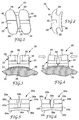
bracket 20b that is somewhat similar to thebracket 20 illustrated in Figs. 1-4. Unless otherwise mentioned, elements of thebracket 20b bearing numerals corresponding to the numbered elements of Figs. 1-4 are similar and consequently will not be described again in detail. - In Fig. 6, however, the web 38b includes a
recess 39b that extends from the occlusal side to the gingival side of thebracket 20b directly below the bottom of thedebonding channel 32b. Therecess 39b has a V-shaped bottom surface that extends in a buccolabial direction away from adjacent regions of the bonding surfaces 34b, 36b of themesial section 22 and thedistal section 24b. Therecess 39b thus interrupts the continuity of the smoothly curved, convex shape of theadjacent bonding surfaces bracket 20b is debonded, therecess 39b facilitates concentration of stresses along the longitudinal, central axis of the web 38b, such that in all likelihood thebracket 20b will fracture along the narrowest section of the web 38b while other portions of thebracket 20b do not fracture and instead remain intact. - In the embodiment shown in Figs. 7-9, a
bracket 20c is again somewhat similar to thebracket 20 described in connection with Figs. 1-4, and the numerals in Figs. 7-9 refer to elements that are substantially identical to the elements bearing corresponding numerals in Figs. 1-4 except as explained in the paragraphs that follow. - The
bracket 20c includes an elongated, one-piece metallicarchwire slot liner 48c that extends across themesial section 22c and thedistal section 24c. As illustrated in Fig. 9, theliner 48c has a rectangular configuration in transverse cross-section to receive a rectangular archwire in mating relation. Themesial section 22c and thedistal section 24c each have a mesiodistally extending slot of sufficient dimensions to receive thearchwire slot liner 48c. - Preferably, the
archwire slot liner 48c is made of type 303 stainless steel having a thickness of 0.05 mm. Preferably, thearchwire slot liner 48c is brazed to the mesial anddistal sections liner 48c to impose compressive forces on thesections bracket 20c is cooled after the brazing operation. - When the
bracket 20c is debonded from a tooth by urging the mesial anddistal sections debonding channel 32c. Advantageously, thearchwire slot liner 48c is securely fixed to the mesial anddistal sections sections bracket 20c from the mouth in one piece. Thearchwire slot liner 48c also enhances sliding motion of thebracket 20c along the archwire. - A
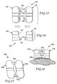
bracket 20d as shown in Fig. 10 is somewhat similar to thebracket 20c shown in Figs. 7-9, except that amesial section 22d and adistal section 24d are made as discrete units and are not integrally connected together. Thebracket 20d does not have a single web that integrally interconnects thesections web 38c, but instead has a two-part web 38d that includes anelongated tab 52d that is integrally connected to the base of thedistal section 24d, and agroove 54d that is integrally connected to the base of themesial section 22d. Thetab 52d and thegroove 54d provide registration structure that facilitates retaining the mesial anddistal sections - The
tab 52d and thegroove 54d have mating convex and concave configurations respectively, and extend the entire occlusal-gingival distance of thebracket 20d below the debonding channel 32d. Optionally, a thin layer of adhesive is applied to the interengaged surfaces of thetab 52d and thegroove 54d to assist in retaining the mesial anddistal sections bracket 20d and during such time that thebracket 20d is used in therapy. The adhesive bond, however, is sufficiently weak to provide a fracture path for theweb 38d that is parallel to the longitudinal axis of the channel 32d when debonding thebracket 20d. A suitable adhesive bond is made by applying a glass frit to thetab 52d and thegroove 54d before assembly, and then firing the assembledsections sections - Figs. 11 and 12 illustrate a
bracket 20e according to another embodiment of the invention that is somewhat similar to thebracket 20d shown in Fig. 10. However, thebracket 20e as shown in Figs. 11 and 12 have mesial anddistal sections archwire slot liner 48e. As such, thedebonding channel 32e extends from the labial side of thebracket 20e to thebonding surfaces - The embodiments illustrated in Fig. 10 and Figs. 11-12 provide a manufacturing advantage, especially when a dry pressing technique is utilized to make the
brackets mesial sections distal sections brackets 20d-e directly to a tooth. - Further, in some instances, the mesial section and the distal section in the embodiments shown in Figs. 10 and 11-12 may be identical, such that a single mold or die can be used to make both sections. In such an instance, it is preferred to replace the compound curved bonding surfaces of the mesial and distal sections with generically curved surfaces that are oriented to approximate the orientation of the underlying tooth surface, and use an orthodontic adhesive with sufficient strength to overcome the resulting lack of a precise, matching configuration between the compound curve of the external tooth surface and the bracket base. Optionally, the slot liner may be curved along its length in the labial-lingual/mesial-distal plane to enhance the fit between the tooth surface and the bracket base.
- Figs. 13-14 depict a
bracket 20f according to another embodiment of the invention. Thebracket 20f has amesial section 22f and adistal section 24f that advantageously are identical and consequently reduce the costs of manufacture. Each self-mating section peg 25f that is received in amating hole 27f of theother section pegs 25f in theholes 27f. As another alternative,bracket 20f may include a metal archwire slot liner to enhance sliding mechanics and also to assist in retaining thesections pegs 25f break as thesections gingival debonding channel 32f. - Figs. 15-16 illustrate a
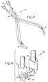
bracket 20g according to another embodiment of the invention. Thebracket 20g is substantially similar to thebracket 20 shown in Figs. 1-4, but includes a pair of spaced-apartbridges 29g that integrally interconnect mesial anddistal sections bridges 29g are spaced buccolabially fromfrangible web 38g and enhance the strength of thebracket 20g. However,bridges 29g are readily removed with a diamond burr prior to debonding; subsequently thesections bridges 29g may be used with the other brackets described above. - An orthodontic debonding tool for debonding the brackets mentioned above is shown in Figs. 17 and 18 and is designated by the numeral 60. The
tool 60 is shown for illustrative purposes in Fig. 18 as used in connection with thebracket 20, but is also useful for debonding other brackets according to the invention such asbrackets 20a-20e. Thedebonding tool 60 has a pliers-like configuration and includes a pair ofopposed jaws 62 as well as a pair ofhandles 64. - Each of the
handles 64 is connected to a respective one of thejaws 62, and thehandles 64 and thejaws 62 are essentially identical. The handles are coupled together by apivot 66 that enables thejaws 62 to move toward and away from each other as thehandles 64 are moved toward or away from each other. - Each of the
jaws 62 includes an outer end portion having awall 68 for engaging either themesial side 42 or thedistal side 44 of thebracket 20. Eachjaw 62 also includes awall 70 oriented perpendicular to thewall 68, for engaging the labial surface of thebracket 20, or alternatively the labial side of anarchwire 72 that is received in thearchwire slot 30 of thebracket 20. A groove 74 extends through thewall 68 for straddling thearchwire 72 in the manner shown in Fig. 18. - The
walls 70 function as a stop to limit the lingual depth of engagement of thewalls 68 with the respective mesial anddistal sides bracket 20. Thus, when thehandles 64 are squeezed together to close thejaws 62, thewalls 68 apply compressive forces only to labial portions of the mesial anddistal sections bracket 20 in areas lingually of the bottom of thedebonding channel 32. Such construction facilitates rocking of the mesial anddistal sections web 38 and helps insure that theweb 38 will fracture in a direction along the longitudinal axis of thechannel 32. Consequently, the probability is increased that thebracket 20 will fracture into only two pieces (i.e., the mesial anddistal sections 22, 24) or, at most, three pieces (i.e., thesections walls archwire 72 has been removed, so that the broken pieces do not fall into the oral cavity. - Another advantage of the present invention is that a set of
brackets 20 can be debonded from corresponding teeth in one arch of the mouth while all ofsuch brackets 20 remain connected to thecommon archwire 72 by ligatures (not shown in Fig. 18) that are conventionally used during orthodontic treatment. The groove 74 enables thejaws 62 to be placed over thearchwire 72 as well as thebracket 20 while enabling the ligature to remain in place to couple thebracket 20 to thearchwire 72. The orthodontist can debond eachbracket 20 in turn, and then lift thearchwire 72 with all attachedbrackets 20 from the mouth. Such an advantage is important because less time is needed for debonding, and there is less likelihood that one or more of thebrackets 20 will drop into the oral cavity and become ingested or aspirated during the debonding operation. - In the
bracket 20 shown in Fig. 18, thearchwire 72 is received in thearchwire slot 30 to such a lingual depth that the labial side of thearchwire 72 is located lingually of the labial side of thebracket 20. As such, thewalls 70 engage the labial sides of the mesial anddistal sections walls 68 with the mesial anddistal sides wall 70 may include a protruding portion for engaging the labial side of thearchwire 72, or alternatively thearchwire slot 30 of thebracket 20 may be located nearer the labial side of thebracket 20, so that engagement of thewall 70 with thearchwire 72 serves to limit the depth of lingual engagement of thewalls 68 on the mesial anddistal sides - The
debonding tool 60 is preferably made of a corrosion resistant 400 series stainless steel, such as type 420, that is suitable for repeated sterilization. As an alternative to the straight-line configuration of thetool 60 illustrated in Figs. 17 and 18, the jaws may extend in a direction at an angle in the range of about 25 to 40 degrees relative to the major extent of the handles, to facilitate access to brackets bonded to posterior teeth.
Claims (7)
- A ceramic orthodontic bracket (20) comprising a mesial section (22), a distal section (24) and an archwire slot (30) extending in a generally mesial-distal direction in said mesial section (22) and said distal section (24), said bracket (20) including an elongated channel (32) extending in a generally occlusal-gingival direction between said mesial section (22) and said distal section (24), said channel (32) having a depth in a lingual direction that is greater than the lingual depth of said archwire slot (30), said bracket (20) including a frangible web (38) interconnecting said mesial section (22) and said distal section (24) lingually of said channel (32) and extending along the length of said channel (32), said web (38) having thickness in a labial-lingual direction sufficiently small to flex on fracture to enable said bracket (20) to be debonded from a tooth (40) by rocking said mesial section (22) and said distal section (24) about a reference axis extending generally parallel to the longitudinal axis of said channel (32).
- The bracket (20) of claim 1, wherein said web (38) integrally interconnects said mesial section (22) and said distal section (24).
- The bracket (20) of claim 1, wherein said web (38) includes two parts (52d,54d) connected by an adhesive that fractures when said bracket (20) is debonded from a tooth (40).
- The bracket (20) of any of claims 1 to 3, wherein said mesial section (22) and said distal section (24) each include an external surface (34,36) for bonding said bracket (20) to a tooth (40), and wherein said bracket (20) includes a recess (39b) extending between said external surface (34) of said mesial section (22) and said external surface (36) of said distal section (24) in a generally occlusal-gingival direction and generally parallel to said channel (32), said recess (39b) having a bottom surface that is spaced buccolabially from adjacent regions of said external surface (34,36) of said mesial section (22) and said distal section (24).
- The bracket (20) of any of claims 1 to 4 and including a metal liner (48) interconnecting said mesial section (22) and said distal section (24).
- The bracket (20) of any of claims 1 to 5, wherein said mesial section (22) and said distal section (24) are substantially identical.
- The bracket (20) of any of claims 1 to 6, including at least one bridge (29) extending between said mesial section (22) and said distal section (24), said bridge (29) being spaced buccolabially from said web (38).
Priority Applications (3)
| Application Number | Priority Date | Filing Date | Title |
|---|---|---|---|
| EP00105396A EP1004279B1 (en) | 1993-11-29 | 1994-11-28 | Ceramic orthodontic bracket with debonding channel |
| DE9422347U DE9422347U1 (en) | 1993-11-29 | 1994-11-28 | Ceramic orthodontic bracket with release groove |
| DE9422346U DE9422346U1 (en) | 1993-11-29 | 1994-11-28 | Ceramic orthodontic bracket with release groove |
Applications Claiming Priority (2)
| Application Number | Priority Date | Filing Date | Title |
|---|---|---|---|
| US08/159,060 US5439379A (en) | 1993-11-29 | 1993-11-29 | Ceramic orthodontic bracket with debonding channel |
| US159060 | 1993-11-29 |
Related Child Applications (1)
| Application Number | Title | Priority Date | Filing Date |
|---|---|---|---|
| EP00105396A Division EP1004279B1 (en) | 1993-11-29 | 1994-11-28 | Ceramic orthodontic bracket with debonding channel |
Publications (3)
| Publication Number | Publication Date |
|---|---|
| EP0656195A2 EP0656195A2 (en) | 1995-06-07 |
| EP0656195A3 EP0656195A3 (en) | 1995-08-16 |
| EP0656195B1 true EP0656195B1 (en) | 2000-10-18 |
Family
ID=22570917
Family Applications (2)
| Application Number | Title | Priority Date | Filing Date |
|---|---|---|---|
| EP00105396A Expired - Lifetime EP1004279B1 (en) | 1993-11-29 | 1994-11-28 | Ceramic orthodontic bracket with debonding channel |
| EP94118719A Expired - Lifetime EP0656195B1 (en) | 1993-11-29 | 1994-11-28 | Ceramic orthodontic bracket with debonding channel |
Family Applications Before (1)
| Application Number | Title | Priority Date | Filing Date |
|---|---|---|---|
| EP00105396A Expired - Lifetime EP1004279B1 (en) | 1993-11-29 | 1994-11-28 | Ceramic orthodontic bracket with debonding channel |
Country Status (4)
| Country | Link |
|---|---|
| US (1) | US5439379A (en) |
| EP (2) | EP1004279B1 (en) |
| JP (1) | JP3103279B2 (en) |
| DE (3) | DE69426145T2 (en) |
Cited By (1)
| Publication number | Priority date | Publication date | Assignee | Title |
|---|---|---|---|---|
| EP1639960A1 (en) | 2004-09-27 | 2006-03-29 | Ferton Holding SA | Device and method for removing tooth applications such as brackets |
Families Citing this family (68)
| Publication number | Priority date | Publication date | Assignee | Title |
|---|---|---|---|---|
| US5607301A (en) * | 1994-11-01 | 1997-03-04 | Lancer Orthodontics | Orthodontic bracket and method of mounting |
| US5681165A (en) * | 1995-05-09 | 1997-10-28 | Feldman; Randy Mark | Ceramic orthodontic bracket and method of manufacturing |
| US6634051B1 (en) * | 1997-09-22 | 2003-10-21 | Centrix, Inc. | Disposable dental applicator |
| US5879156A (en) * | 1997-10-29 | 1999-03-09 | Deleo; David B. | Orthodontic apparatus for attachment to teeth |
| US6142775A (en) | 1999-07-14 | 2000-11-07 | 3M Innovative Properties Company | Occlusal cap for orthodontic bracket |
| US6302688B1 (en) | 1999-09-27 | 2001-10-16 | 3M Innovative Properties Company | Orthodontic appliance with self-releasing latch |
| US6364659B1 (en) | 2000-02-23 | 2002-04-02 | 3M Innovative Properties Company | Orthodontic bite opener |
| US6474988B1 (en) | 2000-03-08 | 2002-11-05 | 3M Innovative Properties Company | Hand instrument for debonding orthodontic brackets |
| US6382965B1 (en) * | 2000-04-25 | 2002-05-07 | Ormco Corporation | Orthodontic debonding tools and methods |
| US6464494B1 (en) * | 2000-07-28 | 2002-10-15 | David V. Young | Composite orthodontic device |
| JP2002224140A (en) | 2001-02-06 | 2002-08-13 | Tomii Kk | Orthodontic member |
| US6554612B2 (en) | 2001-06-25 | 2003-04-29 | 3M Innovative Properties Company | Orthodontic bracket with recessed attachment and method for making the same |
| US6648638B2 (en) | 2001-12-28 | 2003-11-18 | 3M Innovative Properties Company | Orthodontic appliances including polycrystalline alumina-based ceramic material, kits, and methods |
| US6878456B2 (en) | 2001-12-28 | 2005-04-12 | 3M Innovative Properties Co. | Polycrystalline translucent alumina-based ceramic material, uses, and methods |
| US20030226882A1 (en) * | 2002-05-03 | 2003-12-11 | Jose Porchia | Corrugated paperboard dishware and cookware |
| US6929475B1 (en) * | 2002-10-04 | 2005-08-16 | Centrix, Inc. | Pre-dosed applicator and applicator system |
| US7695277B1 (en) | 2004-10-28 | 2010-04-13 | Rmo, Inc. | Orthodontic bracket with frangible cover mechanism |
| US7014460B2 (en) * | 2002-11-04 | 2006-03-21 | 3M Innovative Properties Company | Orthodontic appliance with fatigue-resistant archwire retaining latch |
| US6893257B2 (en) * | 2002-12-19 | 2005-05-17 | 3M Innovative Properties Company | Orthodontic appliance with placement enhancement structure |
| US6910884B2 (en) * | 2002-12-19 | 2005-06-28 | 3M Innovative Properties Company | Low profile orthodontic appliance |
| US20040219470A1 (en) * | 2003-05-02 | 2004-11-04 | Ormco Corporation | Orthodontic bracket and method of debonding a bracket |
| US7318302B2 (en) * | 2003-07-10 | 2008-01-15 | Opperman Investments, Ltd. | Equipment support for a metal building |
| US7140876B2 (en) * | 2003-10-31 | 2006-11-28 | 3M Innovative Properties Company | Orthodontic appliance with latch for retaining an archwire |
| US7192274B2 (en) * | 2003-12-08 | 2007-03-20 | 3M Innovative Properties Company | Ceramic orthodontic appliance with archwire slot liner |
| US7140875B2 (en) * | 2004-02-03 | 2006-11-28 | 3M Innovative Properties Company | Orthodontic bracket with reinforced tiewings |
| US7153130B2 (en) * | 2004-06-10 | 2006-12-26 | 3M Innovative Properties Company | Orthodontic appliance with removable insert |
| US20050277084A1 (en) * | 2004-06-10 | 2005-12-15 | 3M Innovative Properties Company | Orthodontic brace with polymeric arch member |
| US7677887B2 (en) * | 2004-07-02 | 2010-03-16 | Nicholson James A | Shape memory self-ligating orthodontic brackets |
| US7252505B2 (en) * | 2004-07-28 | 2007-08-07 | 3M Innovative Properties Company | Self-ligating orthodontic appliance with post for connection to a latch |
| US20060024634A1 (en) * | 2004-07-28 | 2006-02-02 | 3M Innovative Properties Company | Self-ligating orthodontic appliance with clip |
| JP5168766B2 (en) * | 2004-08-27 | 2013-03-27 | 東ソー株式会社 | Orthodontic bracket and manufacturing method thereof |
| WO2006022384A1 (en) | 2004-08-27 | 2006-03-02 | Tosoh Corporation | Orthodontic bracket and process for producing the same |
| US7549860B2 (en) * | 2004-12-13 | 2009-06-23 | 3M Innovative Properties Company | Hand instrument for detaching orthodontic brackets from teeth |
| US7819660B2 (en) * | 2005-10-26 | 2010-10-26 | Cosse Christopher C | Reusable multi-piece orthodontic appliances |
| US7581949B2 (en) * | 2005-11-28 | 2009-09-01 | Ormco Corporation | Debonding pliers |
| US20070142498A1 (en) * | 2005-12-20 | 2007-06-21 | Brennan Joan V | Dental compositions including thermally responsive additives, and the use thereof |
| US7776940B2 (en) | 2005-12-20 | 2010-08-17 | 3M Innovative Properties Company | Methods for reducing bond strengths, dental compositions, and the use thereof |
| US8026296B2 (en) | 2005-12-20 | 2011-09-27 | 3M Innovative Properties Company | Dental compositions including a thermally labile component, and the use thereof |
| US7896650B2 (en) | 2005-12-20 | 2011-03-01 | 3M Innovative Properties Company | Dental compositions including radiation-to-heat converters, and the use thereof |
| US7377777B2 (en) | 2005-12-23 | 2008-05-27 | 3M Innovative Properties Company | Orthodontic appliance with archwire-engaging clip |
| US7771640B2 (en) | 2006-02-17 | 2010-08-10 | Cosse Christopher C | Orthodontic treatment methods, systems and apparatus for use therewith |
| JP2009532134A (en) * | 2006-03-31 | 2009-09-10 | アールエムオー,インコーポレイテツド | Orthodontic bracket with liner archwire slot and cover |
| US9554875B2 (en) | 2006-09-07 | 2017-01-31 | Rmo, Inc. | Method for producing a customized orthodontic appliance |
| US8251697B2 (en) | 2006-09-07 | 2012-08-28 | Rmo, Inc. | Reduced-friction buccal tube and method of use |
| US8979528B2 (en) | 2006-09-07 | 2015-03-17 | Rmo, Inc. | Customized orthodontic appliance method and system |
| US20080070182A1 (en) * | 2006-09-20 | 2008-03-20 | 3M Innovative Properties Company | Orthodontic elements and other medical devices with a fluorinated polymer, and methods |
| US9539065B2 (en) * | 2006-10-23 | 2017-01-10 | 3M Innovative Properties Company | Assemblies, methods, and kits including a compressible material |
| US7670140B2 (en) * | 2006-12-20 | 2010-03-02 | 3M Innovative Properties Company | Orthodontic hand instrument for detaching brackets from teeth |
| JP5215381B2 (en) * | 2007-04-30 | 2013-06-19 | スリーエム イノベイティブ プロパティズ カンパニー | Ceramic orthodontic bracket with improved release characteristics |
| US7686613B2 (en) * | 2007-07-10 | 2010-03-30 | 3M Innovative Properties Company | Narrow ceramic self-ligating orthodontic bracket |
| WO2010014518A2 (en) | 2008-07-30 | 2010-02-04 | 3M Innovative Properties Company | Low profile self-ligating orthodontic appliance with clip |
| US8585398B2 (en) | 2008-08-13 | 2013-11-19 | Ormco Corporation | Aesthetic orthodontic bracket and method of making same |
| AU2009238317B2 (en) * | 2008-11-14 | 2011-10-06 | Ormco Corporation | Surface treated polycrystalline ceramic orthodontic bracket and method of making same |
| DE102009011132A1 (en) | 2009-03-03 | 2010-09-30 | Judo Wasseraufbereitung Gmbh | Method for operating a water softening system with setpoint control by a water removal station |
| WO2010105066A1 (en) * | 2009-03-13 | 2010-09-16 | Ultradent Products, Inc. | Orthodontic brackets including a ceramic or polymer bracket base and a metal insert having a selectively removable labial web cover |
| US11219507B2 (en) | 2009-03-16 | 2022-01-11 | Orthoamerica Holdings, Llc | Customized orthodontic appliance and method |
| WO2010107567A1 (en) | 2009-03-16 | 2010-09-23 | Rmo, Inc. | Orthodontic bracket having an archwire channel and archwire retaining mechanism |
| DE102009058246A1 (en) * | 2009-12-11 | 2011-06-16 | Bernhard Förster Gmbh | A method for detaching an orthodontic bracket from the surface of a tooth |
| KR100989407B1 (en) * | 2010-02-04 | 2010-10-25 | 문성혜 | Orthodontic bracket |
| US9289273B2 (en) * | 2011-01-12 | 2016-03-22 | Robert N. Staley | Method and system for bodily translating a tooth with a wide and adjustable width brackets |
| US11382722B2 (en) * | 2011-03-17 | 2022-07-12 | Cameron Mashouf | Orthodontic brackets for deciduous teeth |
| US10433933B2 (en) | 2011-03-17 | 2019-10-08 | Cameron Mashouf | Orthodontic bracket for use on deciduous teeth |
| EP2706949B1 (en) | 2011-05-12 | 2019-11-13 | Rmo, Inc. | Orthodontic appliance with encoded information formed in the base |
| USD847349S1 (en) | 2011-09-22 | 2019-04-30 | Rmo, Inc. | Orthodontic lock with flange |
| CN104812328B (en) | 2012-07-23 | 2018-04-27 | 3M创新有限公司 | Self-ligating orthodontic bracket |
| US11083548B2 (en) | 2018-01-26 | 2021-08-10 | Todd Evan Dickerson | Orthodontic anterior bite plate |
| US11872101B2 (en) * | 2018-04-25 | 2024-01-16 | Lightforce Orthodontics, Inc. | Manufacture of patient-specific orthodontic brackets with improved base and retentive features |
| CA3102465A1 (en) | 2018-06-12 | 2019-12-19 | Lightforce Orthodontics, Inc. | Ceramic processing and design for the direct manufacture of customized labial and lingual orthodontic clear aligner attachments |
Family Cites Families (23)
| Publication number | Priority date | Publication date | Assignee | Title |
|---|---|---|---|---|
| US3986265A (en) * | 1975-06-09 | 1976-10-19 | Henry Mann, Inc. | Orthodontic tool for removing epoxy secured brackets and epoxy residue |
| US4043364A (en) * | 1976-11-24 | 1977-08-23 | E.T.M. Corporation | Plier set for making torquing bends in orthodontic arch wires |
| US4249897A (en) * | 1978-01-17 | 1981-02-10 | Anderson Roland M | Modular cushioning orthodontic bracket structure |
| US4256455A (en) * | 1978-04-27 | 1981-03-17 | Bernhard Forster Gmbh | Orthodontic bracket and orthodontic appliance |
| US4216583A (en) * | 1978-08-03 | 1980-08-12 | Zulauf Inc. | Orthodontic appliance |
| US4219617A (en) * | 1978-08-09 | 1980-08-26 | Melvin Wallshein | Ceramic orthodontic bracket |
| US4248587A (en) * | 1979-10-22 | 1981-02-03 | Kurz Craven H | Orthodontic tool |
| US4553932A (en) * | 1983-04-29 | 1985-11-19 | Maclay M. Armstrong | Method and implement for pulling bonded orthodontic brackets off teeth |
| DE3588089T2 (en) * | 1984-04-23 | 1996-10-02 | Johnson & Johnson Dental Prod | Orthodontic bracket made of crystalline aluminum oxide |
| US4681538A (en) * | 1984-04-23 | 1987-07-21 | Johnson & Johnson Dental Products, Company | Crystalline alumina composites |
| CA1326382C (en) * | 1986-05-08 | 1994-01-25 | John Steven Kelly | Ceramic orthodontic appliance |
| US4904183A (en) * | 1987-05-08 | 1990-02-27 | Unitek Corporation | Orthodontic debonding method and tool |
| US4776791A (en) * | 1988-01-12 | 1988-10-11 | Johnson & Johnson Consumer Products, Inc. | Shield for a pair of orthodontic pliers for use in removing dental brackets |
| US4950157A (en) * | 1988-11-14 | 1990-08-21 | Unitek Corporation | Debonding instrument for orthodontic brackets |
| JPH0681622B2 (en) * | 1989-06-20 | 1994-10-19 | トミー株式会社 | Orthodontic bracket |
| US5074783A (en) * | 1989-11-16 | 1991-12-24 | Ormco Corporation | Orthodontic bracket coated with water-soluble dye |
| ATE113189T1 (en) * | 1990-02-07 | 1994-11-15 | Ormco Corp | ORTHODONTIC BRACKET AND METHOD OF MANUFACTURE. |
| US5098288A (en) * | 1990-05-04 | 1992-03-24 | Tp Orthodontics, Inc. | Flexible bonding pad for an orthodontic bracket |
| US5108285A (en) * | 1991-09-30 | 1992-04-28 | American Orthodontics Corporation | Bonding base and method of making same for a ceramic orthodontic bracket |
| US5263859A (en) * | 1992-05-08 | 1993-11-23 | Tp Orthodontics, Inc. | Relatively flexible bonding pad for an orthodontic ceramic bracket |
| US5256062A (en) * | 1992-06-30 | 1993-10-26 | Johnson & Johnson Consumer Products, Inc. | Combination metallic ceramic orthodontic bracker |
| US5380196A (en) | 1993-05-13 | 1995-01-10 | Minnesota Mining And Manufacturing Company | Orthodontic bracket with archwire slot liner |
| US6121593A (en) | 1998-08-19 | 2000-09-19 | Duck Creek Energy, Inc. | Home appliances provided with control systems which may be actuated from a remote location |
-
1993
- 1993-11-29 US US08/159,060 patent/US5439379A/en not_active Expired - Lifetime
-
1994
- 1994-11-21 JP JP28647094A patent/JP3103279B2/en not_active Expired - Lifetime
- 1994-11-28 DE DE69426145T patent/DE69426145T2/en not_active Expired - Lifetime
- 1994-11-28 DE DE69434440T patent/DE69434440T2/en not_active Expired - Lifetime
- 1994-11-28 EP EP00105396A patent/EP1004279B1/en not_active Expired - Lifetime
- 1994-11-28 DE DE1004279T patent/DE1004279T1/en active Pending
- 1994-11-28 EP EP94118719A patent/EP0656195B1/en not_active Expired - Lifetime
Cited By (1)
| Publication number | Priority date | Publication date | Assignee | Title |
|---|---|---|---|---|
| EP1639960A1 (en) | 2004-09-27 | 2006-03-29 | Ferton Holding SA | Device and method for removing tooth applications such as brackets |
Also Published As
| Publication number | Publication date |
|---|---|
| DE69434440T2 (en) | 2006-05-24 |
| DE69426145T2 (en) | 2001-03-08 |
| EP1004279B1 (en) | 2005-07-27 |
| DE1004279T1 (en) | 2001-03-01 |
| EP1004279A1 (en) | 2000-05-31 |
| JP3103279B2 (en) | 2000-10-30 |
| DE69434440D1 (en) | 2005-09-01 |
| JPH07194623A (en) | 1995-08-01 |
| EP0656195A2 (en) | 1995-06-07 |
| EP0656195A3 (en) | 1995-08-16 |
| DE69426145D1 (en) | 2000-11-23 |
| US5439379A (en) | 1995-08-08 |
Similar Documents
| Publication | Publication Date | Title |
|---|---|---|
| EP0656195B1 (en) | Ceramic orthodontic bracket with debonding channel | |
| EP0655226B1 (en) | Method and apparatus for debonding ceramic orthodontic brackets | |
| US7140875B2 (en) | Orthodontic bracket with reinforced tiewings | |
| US7153130B2 (en) | Orthodontic appliance with removable insert | |
| US7192274B2 (en) | Ceramic orthodontic appliance with archwire slot liner | |
| US7686613B2 (en) | Narrow ceramic self-ligating orthodontic bracket | |
| EP3478215B1 (en) | Self-ligating orthodontic bracket | |
| US7670140B2 (en) | Orthodontic hand instrument for detaching brackets from teeth | |
| US6474988B1 (en) | Hand instrument for debonding orthodontic brackets | |
| EP3745993B1 (en) | Ceramic self-ligating bracket with high labial pull strength | |
| EP2142134B1 (en) | Ceramic orthodontic bracket with improved debonding characteristics | |
| US7549860B2 (en) | Hand instrument for detaching orthodontic brackets from teeth |
Legal Events
| Date | Code | Title | Description |
|---|---|---|---|
| PUAI | Public reference made under article 153(3) epc to a published international application that has entered the european phase |
Free format text: ORIGINAL CODE: 0009012 |
|
| AK | Designated contracting states |
Kind code of ref document: A2 Designated state(s): DE FR GB IT |
|
| PUAL | Search report despatched |
Free format text: ORIGINAL CODE: 0009013 |
|
| AK | Designated contracting states |
Kind code of ref document: A3 Designated state(s): DE FR GB IT |
|
| 17P | Request for examination filed |
Effective date: 19960202 |
|
| 17Q | First examination report despatched |
Effective date: 19980302 |
|
| GRAG | Despatch of communication of intention to grant |
Free format text: ORIGINAL CODE: EPIDOS AGRA |
|
| GRAG | Despatch of communication of intention to grant |
Free format text: ORIGINAL CODE: EPIDOS AGRA |
|
| GRAH | Despatch of communication of intention to grant a patent |
Free format text: ORIGINAL CODE: EPIDOS IGRA |
|
| GRAH | Despatch of communication of intention to grant a patent |
Free format text: ORIGINAL CODE: EPIDOS IGRA |
|
| GRAH | Despatch of communication of intention to grant a patent |
Free format text: ORIGINAL CODE: EPIDOS IGRA |
|
| GRAA | (expected) grant |
Free format text: ORIGINAL CODE: 0009210 |
|
| AK | Designated contracting states |
Kind code of ref document: B1 Designated state(s): DE FR GB IT |
|
| REF | Corresponds to: |
Ref document number: 69426145 Country of ref document: DE Date of ref document: 20001123 |
|
| ET | Fr: translation filed | ||
| ITF | It: translation for a ep patent filed |
Owner name: ING. C. GREGORJ S.P.A. |
|
| PLBE | No opposition filed within time limit |
Free format text: ORIGINAL CODE: 0009261 |
|
| STAA | Information on the status of an ep patent application or granted ep patent |
Free format text: STATUS: NO OPPOSITION FILED WITHIN TIME LIMIT |
|
| 26N | No opposition filed | ||
| REG | Reference to a national code |
Ref country code: GB Ref legal event code: IF02 |
|
| PGFP | Annual fee paid to national office [announced via postgrant information from national office to epo] |
Ref country code: IT Payment date: 20121120 Year of fee payment: 19 |
|
| PGFP | Annual fee paid to national office [announced via postgrant information from national office to epo] |
Ref country code: GB Payment date: 20131127 Year of fee payment: 20 Ref country code: FR Payment date: 20131108 Year of fee payment: 20 Ref country code: DE Payment date: 20131120 Year of fee payment: 20 |
|
| PG25 | Lapsed in a contracting state [announced via postgrant information from national office to epo] |
Ref country code: IT Free format text: LAPSE BECAUSE OF NON-PAYMENT OF DUE FEES Effective date: 20131128 |
|
| REG | Reference to a national code |
Ref country code: DE Ref legal event code: R071 Ref document number: 69426145 Country of ref document: DE |
|
| REG | Reference to a national code |
Ref country code: DE Ref legal event code: R071 Ref document number: 69426145 Country of ref document: DE |
|
| REG | Reference to a national code |
Ref country code: GB Ref legal event code: PE20 Expiry date: 20141127 |
|
| PG25 | Lapsed in a contracting state [announced via postgrant information from national office to epo] |
Ref country code: GB Free format text: LAPSE BECAUSE OF EXPIRATION OF PROTECTION Effective date: 20141127 |