EP0655758A1 - A light emitting push button - Google Patents
A light emitting push button Download PDFInfo
- Publication number
- EP0655758A1 EP0655758A1 EP94850202A EP94850202A EP0655758A1 EP 0655758 A1 EP0655758 A1 EP 0655758A1 EP 94850202 A EP94850202 A EP 94850202A EP 94850202 A EP94850202 A EP 94850202A EP 0655758 A1 EP0655758 A1 EP 0655758A1
- Authority
- EP
- European Patent Office
- Prior art keywords
- light
- button
- push button
- light emitting
- upper side
- Prior art date
- Legal status (The legal status is an assumption and is not a legal conclusion. Google has not performed a legal analysis and makes no representation as to the accuracy of the status listed.)
- Granted
Links
- 239000000463 material Substances 0.000 claims abstract description 14
- 239000004020 conductor Substances 0.000 claims abstract description 12
- 230000001419 dependent effect Effects 0.000 description 1
- 238000000034 method Methods 0.000 description 1
- 238000012986 modification Methods 0.000 description 1
- 230000004048 modification Effects 0.000 description 1
- 238000000465 moulding Methods 0.000 description 1
Images
Classifications
-
- H—ELECTRICITY
- H01—ELECTRIC ELEMENTS
- H01H—ELECTRIC SWITCHES; RELAYS; SELECTORS; EMERGENCY PROTECTIVE DEVICES
- H01H13/00—Switches having rectilinearly-movable operating part or parts adapted for pushing or pulling in one direction only, e.g. push-button switch
- H01H13/02—Details
- H01H13/023—Light-emitting indicators
-
- H—ELECTRICITY
- H01—ELECTRIC ELEMENTS
- H01H—ELECTRIC SWITCHES; RELAYS; SELECTORS; EMERGENCY PROTECTIVE DEVICES
- H01H9/00—Details of switching devices, not covered by groups H01H1/00 - H01H7/00
- H01H9/18—Distinguishing marks on switches, e.g. for indicating switch location in the dark; Adaptation of switches to receive distinguishing marks
- H01H9/182—Illumination of the symbols or distinguishing marks
-
- H—ELECTRICITY
- H01—ELECTRIC ELEMENTS
- H01H—ELECTRIC SWITCHES; RELAYS; SELECTORS; EMERGENCY PROTECTIVE DEVICES
- H01H2219/00—Legends
- H01H2219/054—Optical elements
- H01H2219/056—Diffuser; Uneven surface
-
- Y—GENERAL TAGGING OF NEW TECHNOLOGICAL DEVELOPMENTS; GENERAL TAGGING OF CROSS-SECTIONAL TECHNOLOGIES SPANNING OVER SEVERAL SECTIONS OF THE IPC; TECHNICAL SUBJECTS COVERED BY FORMER USPC CROSS-REFERENCE ART COLLECTIONS [XRACs] AND DIGESTS
- Y10—TECHNICAL SUBJECTS COVERED BY FORMER USPC
- Y10T—TECHNICAL SUBJECTS COVERED BY FORMER US CLASSIFICATION
- Y10T428/00—Stock material or miscellaneous articles
- Y10T428/16—Two dimensionally sectional layer
- Y10T428/162—Transparent or translucent layer or section
Definitions
- the present invention relates to a light-emitting push button for operating purposes, for instance a number button on a telephone apparatus, wherein the push button includes a body which has been double-molded in two different plastic materials, of which one material is light conductive and the other is opaque.
- a light emitting device such as a light emitting diode, is arranged to emit light on the underside of the press button, so that light will be conducted through the light conductive material and be emitted on the upper side of the button.
- buttons of the aforedescribed kind are known to the art. Although the majority of existing buttons provided with light conductors light up well, there is often an angle or angles of incidence at which the light almost disappears, depending on the line of sight.
- the lens requires free surfaces around the lens, in order for the light to be reflected from the sides and so as to obtain the best possible light yield at the top of the button.
- a light conductor integrated in such a double-molded button, for instance in telephone apparatus, makes it difficult to discern whether the button is lit or not when viewed in a direction towards the button, because the light is not scattered uniformly at the upper surface of the button.
- An object of the present invention is to avoid the drawback of not being able to see the light from all directions, and to provide a press button in which light is scattered uniformly at the top of the button, such that the light yield at the button top will be the best possible for all angles of incidence.
- This object is achieved by forming an air gap or slot which extends to slightly below the top of the lens, between button and lens, so that light will be reflected against the lens surface thus exposed.
- An inventive push button affords the advantage that the light yield will be practically uniform in all directions, or in other words there are found no angles of incidence at which the light will disappear irrespective of the line of sight, but that the button will be clearly visible from all directions.
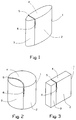
- Figure 1 illustrates in perspective a preferred embodiment of a light-emitting push button 1.
- the push button 1 is ellipsoidal in shape and includes a double-molded body of opaque material 2 and a light conductive material 3 respectively.
- the light conductive material 3 can be considered to form a lens through which light can be conducted from the underside of the button, for instance from a light emitting diode or like device (not shown), up through the lens and radiate from the upper side 4 of the button.
- the slot 5 located between the aforesaid different materials need only have a width of some tenths of a millimeter in order for the desired reflection to be achieved, although from a tool/technical aspect the slot will have a width of about 0.5 mm in practice.
- the push button 1 need not, of course, have the ellipsoidal shape shown in Figure 1.
- Other designs may incorporate the same technical solution, for instance the round press button shown in Figure 2 and the rectangular press button shown in Figure 3.
- the same reference numerals have been used in these latter figures as those used in Figure 1. Press buttons of other designs than those shown may also incorporate the inventive solution.
Landscapes
- Push-Button Switches (AREA)
- Telephone Set Structure (AREA)
Abstract
Description
- The present invention relates to a light-emitting push button for operating purposes, for instance a number button on a telephone apparatus, wherein the push button includes a body which has been double-molded in two different plastic materials, of which one material is light conductive and the other is opaque. A light emitting device, such as a light emitting diode, is arranged to emit light on the underside of the press button, so that light will be conducted through the light conductive material and be emitted on the upper side of the button.
- Light-emitting push buttons of the aforedescribed kind are known to the art. Although the majority of existing buttons provided with light conductors light up well, there is often an angle or angles of incidence at which the light almost disappears, depending on the line of sight. The lens requires free surfaces around the lens, in order for the light to be reflected from the sides and so as to obtain the best possible light yield at the top of the button. A light conductor integrated in such a double-molded button, for instance in telephone apparatus, makes it difficult to discern whether the button is lit or not when viewed in a direction towards the button, because the light is not scattered uniformly at the upper surface of the button.
- This is because the material in the button and the lens is fused or migrated together by heat in the molding process, and the light reflections in this part is "extinguished" or dampened out. A light conductor which is completely molded in would dampen the reflection of light excessively.
- An object of the present invention is to avoid the drawback of not being able to see the light from all directions, and to provide a press button in which light is scattered uniformly at the top of the button, such that the light yield at the button top will be the best possible for all angles of incidence. This object is achieved by forming an air gap or slot which extends to slightly below the top of the lens, between button and lens, so that light will be reflected against the lens surface thus exposed.
- An inventive push button affords the advantage that the light yield will be practically uniform in all directions, or in other words there are found no angles of incidence at which the light will disappear irrespective of the line of sight, but that the button will be clearly visible from all directions.
- The invention will now be described in more detail with reference to an exemplifying embodiment thereof and also with reference to the accompanying drawing.
-
- Figure 1 is a perspective view of an inventive light emitting push button; and
- Figure 2 and Figure 3 are perspective views of alternative embodiments of an inventive light-emitting push button.
- Figure 1 illustrates in perspective a preferred embodiment of a light-emitting
push button 1. Thepush button 1 is ellipsoidal in shape and includes a double-molded body ofopaque material 2 and a lightconductive material 3 respectively. The lightconductive material 3 can be considered to form a lens through which light can be conducted from the underside of the button, for instance from a light emitting diode or like device (not shown), up through the lens and radiate from theupper side 4 of the button. - By providing an
air slot 5 between theopaque material 2 and thelens 3 down to a distance of about 4 mm from the lens top, light is able to reflect against the thus exposedsurface 6 of the lens. Theslot 5 located between the aforesaid different materials need only have a width of some tenths of a millimeter in order for the desired reflection to be achieved, although from a tool/technical aspect the slot will have a width of about 0.5 mm in practice. - Some of the details concerning the design of the press button with regard to its attachment to the equipment to which it belongs, or other elements that are dependent on the function of the push button have not been shown in the drawing. The design of these details and elements will be obvious to one of normal skill in this art and form no part of the present invention.
- The
push button 1 need not, of course, have the ellipsoidal shape shown in Figure 1. Other designs may incorporate the same technical solution, for instance the round press button shown in Figure 2 and the rectangular press button shown in Figure 3. The same reference numerals have been used in these latter figures as those used in Figure 1. Press buttons of other designs than those shown may also incorporate the inventive solution. - It will be understood that the invention is not restricted to the aforedescribed and illustrated embodiment and that modifications can be made within the scope of the following claims.
Claims (3)
- A light emitting push button for operating purposes, for instance a number button on a telephone apparatus, wherein the push button includes a body which is double-molded from two different plastic materials, of which one material is light conductive and the other is opaque, and wherein a light emitting device, such as a light emitting diode, is arranged to emit light on the underside of the push button so that the light is conducted through the light conductor material and is emitted on the upper side of the button, characterized by a slot (5) formed between the light conductive material (3) and the opaque material (2) on the upper side of the button (1), such that light conducted through the light conductive material (3) will be scattered uniformly and therewith visible from all directions.
- A light emitting push button according to claim 1, characterized in that the slot (5) extends to a depth of about 4 mm from the upper side (4) of the button (1).
- A light emitting push button according to claim 1 or claim 2, characterized in that the slot (5) has a width of 0.5 mm.
Applications Claiming Priority (2)
| Application Number | Priority Date | Filing Date | Title |
|---|---|---|---|
| SE9303959 | 1993-11-29 | ||
| SE9303959A SE502066C2 (en) | 1993-11-29 | 1993-11-29 | Light emitting push button |
Publications (2)
| Publication Number | Publication Date |
|---|---|
| EP0655758A1 true EP0655758A1 (en) | 1995-05-31 |
| EP0655758B1 EP0655758B1 (en) | 1998-05-06 |
Family
ID=20391926
Family Applications (1)
| Application Number | Title | Priority Date | Filing Date |
|---|---|---|---|
| EP94850202A Expired - Lifetime EP0655758B1 (en) | 1993-11-29 | 1994-11-10 | A light emitting push button |
Country Status (8)
| Country | Link |
|---|---|
| US (1) | US5584555A (en) |
| EP (1) | EP0655758B1 (en) |
| AT (1) | ATE165934T1 (en) |
| AU (1) | AU676391B2 (en) |
| DE (1) | DE69410064T2 (en) |
| DK (1) | DK0655758T3 (en) |
| ES (1) | ES2118359T3 (en) |
| SE (1) | SE502066C2 (en) |
Cited By (2)
| Publication number | Priority date | Publication date | Assignee | Title |
|---|---|---|---|---|
| FR2790865A1 (en) * | 1999-03-10 | 2000-09-15 | Arnould App Electr | Illuminated electrical switch includes internal reflective surfaces to enhance light output from translucent region of control element |
| EP1727171A1 (en) | 2005-05-25 | 2006-11-29 | Legrand France | Electric device comprising an illuminating control key |
Families Citing this family (7)
| Publication number | Priority date | Publication date | Assignee | Title |
|---|---|---|---|---|
| USD418116S (en) * | 1998-07-17 | 1999-12-28 | Metrol Co., Ltd. | Push-switch with cords |
| USD434387S (en) * | 1998-09-17 | 2000-11-28 | Safety Technology International, Inc. | Switch |
| USD429696S (en) * | 1998-09-17 | 2000-08-22 | Safety Technology International, Inc. | Switch |
| FR2797705B1 (en) * | 1999-08-18 | 2002-10-31 | Eastman Kodak Co | MIXED SIGNALING DEVICE FOR ROOMS WITH MESOPIC ILLUMINATION |
| US6992591B2 (en) * | 2002-02-15 | 2006-01-31 | Jenesis International Inc. | Marker lights for wireless doorbell transmitters and other devices |
| US20080060921A1 (en) * | 2006-09-12 | 2008-03-13 | Motorola, Inc. | Keypad for an electronic device |
| JP6131590B2 (en) * | 2012-12-14 | 2017-05-24 | 富士通株式会社 | Lighting device and electronic device |
Citations (3)
| Publication number | Priority date | Publication date | Assignee | Title |
|---|---|---|---|---|
| EP0310889A2 (en) * | 1987-10-09 | 1989-04-12 | Andreas Peiker | Display device comprising a plurality of light sources |
| US4924044A (en) * | 1986-04-30 | 1990-05-08 | Kabushiki Kaisha Toshiba | Light emitting push button switch for an electronic apparatus |
| US5081329A (en) * | 1990-09-13 | 1992-01-14 | Tie Communications, Inc. | Key assembly, switch assembly and method of making same |
Family Cites Families (7)
| Publication number | Priority date | Publication date | Assignee | Title |
|---|---|---|---|---|
| US2953668A (en) * | 1959-05-14 | 1960-09-20 | Gen Electric | Reversible contrast illuminated control indicator |
| US3163739A (en) * | 1961-09-13 | 1964-12-29 | Gen Electric | Switch with selectively lighted pushbutton actuators |
| DE1655085C3 (en) * | 1967-09-16 | 1974-01-10 | Swf-Spezialfabrik Fuer Autozubehoer Gustav Rau Gmbh, 7120 Bietigheim | Push button switches for vehicles |
| IT1144971B (en) * | 1981-10-21 | 1986-10-29 | Olivetti & Co Spa | CONTACT KEYBOARD |
| US4758701A (en) * | 1984-03-14 | 1988-07-19 | Allen-Bradley Company | Indicator light assembly for control panel |
| JPH0233816A (en) * | 1988-07-21 | 1990-02-05 | Alps Electric Co Ltd | Key top |
| US5510782A (en) * | 1992-08-03 | 1996-04-23 | Itt Corporation | Back lit keypad |
-
1993
- 1993-11-29 SE SE9303959A patent/SE502066C2/en not_active IP Right Cessation
-
1994
- 1994-11-10 DE DE69410064T patent/DE69410064T2/en not_active Expired - Lifetime
- 1994-11-10 EP EP94850202A patent/EP0655758B1/en not_active Expired - Lifetime
- 1994-11-10 ES ES94850202T patent/ES2118359T3/en not_active Expired - Lifetime
- 1994-11-10 DK DK94850202T patent/DK0655758T3/en active
- 1994-11-10 AT AT94850202T patent/ATE165934T1/en not_active IP Right Cessation
- 1994-11-17 US US08/343,903 patent/US5584555A/en not_active Expired - Lifetime
- 1994-11-28 AU AU79084/94A patent/AU676391B2/en not_active Ceased
Patent Citations (3)
| Publication number | Priority date | Publication date | Assignee | Title |
|---|---|---|---|---|
| US4924044A (en) * | 1986-04-30 | 1990-05-08 | Kabushiki Kaisha Toshiba | Light emitting push button switch for an electronic apparatus |
| EP0310889A2 (en) * | 1987-10-09 | 1989-04-12 | Andreas Peiker | Display device comprising a plurality of light sources |
| US5081329A (en) * | 1990-09-13 | 1992-01-14 | Tie Communications, Inc. | Key assembly, switch assembly and method of making same |
Cited By (3)
| Publication number | Priority date | Publication date | Assignee | Title |
|---|---|---|---|---|
| FR2790865A1 (en) * | 1999-03-10 | 2000-09-15 | Arnould App Electr | Illuminated electrical switch includes internal reflective surfaces to enhance light output from translucent region of control element |
| EP1727171A1 (en) | 2005-05-25 | 2006-11-29 | Legrand France | Electric device comprising an illuminating control key |
| FR2886452A1 (en) * | 2005-05-25 | 2006-12-01 | Legrand France | ELECTRICAL EQUIPMENT COMPRISING A LIGHT CONTROL KEY |
Also Published As
| Publication number | Publication date |
|---|---|
| US5584555A (en) | 1996-12-17 |
| DE69410064D1 (en) | 1998-06-10 |
| SE9303959L (en) | 1995-05-30 |
| AU676391B2 (en) | 1997-03-06 |
| SE9303959D0 (en) | 1993-11-29 |
| ES2118359T3 (en) | 1998-09-16 |
| DK0655758T3 (en) | 1999-01-18 |
| ATE165934T1 (en) | 1998-05-15 |
| AU7908494A (en) | 1995-06-08 |
| DE69410064T2 (en) | 1998-11-19 |
| EP0655758B1 (en) | 1998-05-06 |
| SE502066C2 (en) | 1995-07-31 |
Similar Documents
| Publication | Publication Date | Title |
|---|---|---|
| US5266949A (en) | Lighted electronic keyboard | |
| EP0655758B1 (en) | A light emitting push button | |
| JPS5982780A (en) | Lens and mount used together with electromagnetic wave source | |
| GB2140210A (en) | Key switch devices with indicator lamp means | |
| GB1590248A (en) | Light transmitting and/or receiving device | |
| US4924044A (en) | Light emitting push button switch for an electronic apparatus | |
| EP3486560B1 (en) | Display device | |
| US4775767A (en) | Illuminative switch assembly | |
| KR102537647B1 (en) | device and operating device | |
| JPH05109338A (en) | keyboard | |
| JPH0134822Y2 (en) | ||
| JP2783054B2 (en) | Indicator light cover | |
| JP5168780B2 (en) | Light guide plate structure | |
| KR102098235B1 (en) | Emitting apparatus | |
| KR200499523Y1 (en) | Danger signal generator using radar | |
| KR20150106354A (en) | Terminal device | |
| JPH0422391Y2 (en) | ||
| KR0124426Y1 (en) | LED guide lens of printer | |
| US20240142629A1 (en) | Shielding structure and electronic device having the same | |
| CN213909821U (en) | Control panel assembly and cooking utensil with same | |
| KR900003294Y1 (en) | Pushbutton switch | |
| JP4781971B2 (en) | Thin connector with light guide | |
| KR200161366Y1 (en) | Light reflector on the remote control button | |
| KR0125018Y1 (en) | Function mode display device of electronic products | |
| KR920007022Y1 (en) | Switch |
Legal Events
| Date | Code | Title | Description |
|---|---|---|---|
| PUAI | Public reference made under article 153(3) epc to a published international application that has entered the european phase |
Free format text: ORIGINAL CODE: 0009012 |
|
| AK | Designated contracting states |
Kind code of ref document: A1 Designated state(s): AT BE CH DE DK ES FR GB GR IE IT LI LU MC NL PT |
|
| 17P | Request for examination filed |
Effective date: 19951106 |
|
| GRAG | Despatch of communication of intention to grant |
Free format text: ORIGINAL CODE: EPIDOS AGRA |
|
| 17Q | First examination report despatched |
Effective date: 19970728 |
|
| GRAG | Despatch of communication of intention to grant |
Free format text: ORIGINAL CODE: EPIDOS AGRA |
|
| GRAH | Despatch of communication of intention to grant a patent |
Free format text: ORIGINAL CODE: EPIDOS IGRA |
|
| GRAH | Despatch of communication of intention to grant a patent |
Free format text: ORIGINAL CODE: EPIDOS IGRA |
|
| GRAA | (expected) grant |
Free format text: ORIGINAL CODE: 0009210 |
|
| AK | Designated contracting states |
Kind code of ref document: B1 Designated state(s): AT BE CH DE DK ES FR GB GR IE IT LI LU MC NL PT |
|
| REF | Corresponds to: |
Ref document number: 165934 Country of ref document: AT Date of ref document: 19980515 Kind code of ref document: T |
|
| REG | Reference to a national code |
Ref country code: CH Ref legal event code: EP |
|
| REF | Corresponds to: |
Ref document number: 69410064 Country of ref document: DE Date of ref document: 19980610 |
|
| ITF | It: translation for a ep patent filed | ||
| REG | Reference to a national code |
Ref country code: CH Ref legal event code: NV Representative=s name: ISLER & PEDRAZZINI AG |
|
| REG | Reference to a national code |
Ref country code: IE Ref legal event code: FG4D Free format text: 80188 |
|
| ET | Fr: translation filed | ||
| REG | Reference to a national code |
Ref country code: ES Ref legal event code: FG2A Ref document number: 2118359 Country of ref document: ES Kind code of ref document: T3 |
|
| REG | Reference to a national code |
Ref country code: PT Ref legal event code: SC4A Free format text: AVAILABILITY OF NATIONAL TRANSLATION Effective date: 19980730 |
|
| REG | Reference to a national code |
Ref country code: DK Ref legal event code: T3 |
|
| PLBE | No opposition filed within time limit |
Free format text: ORIGINAL CODE: 0009261 |
|
| STAA | Information on the status of an ep patent application or granted ep patent |
Free format text: STATUS: NO OPPOSITION FILED WITHIN TIME LIMIT |
|
| 26N | No opposition filed | ||
| PGFP | Annual fee paid to national office [announced via postgrant information from national office to epo] |
Ref country code: FR Payment date: 19991019 Year of fee payment: 6 |
|
| PGFP | Annual fee paid to national office [announced via postgrant information from national office to epo] |
Ref country code: AT Payment date: 19991020 Year of fee payment: 6 |
|
| PGFP | Annual fee paid to national office [announced via postgrant information from national office to epo] |
Ref country code: DK Payment date: 19991021 Year of fee payment: 6 |
|
| PGFP | Annual fee paid to national office [announced via postgrant information from national office to epo] |
Ref country code: MC Payment date: 19991025 Year of fee payment: 6 |
|
| PGFP | Annual fee paid to national office [announced via postgrant information from national office to epo] |
Ref country code: CH Payment date: 19991026 Year of fee payment: 6 |
|
| PGFP | Annual fee paid to national office [announced via postgrant information from national office to epo] |
Ref country code: NL Payment date: 19991027 Year of fee payment: 6 |
|
| PGFP | Annual fee paid to national office [announced via postgrant information from national office to epo] |
Ref country code: BE Payment date: 19991103 Year of fee payment: 6 |
|
| PGFP | Annual fee paid to national office [announced via postgrant information from national office to epo] |
Ref country code: PT Payment date: 19991105 Year of fee payment: 6 |
|
| PGFP | Annual fee paid to national office [announced via postgrant information from national office to epo] |
Ref country code: ES Payment date: 19991111 Year of fee payment: 6 |
|
| PGFP | Annual fee paid to national office [announced via postgrant information from national office to epo] |
Ref country code: LU Payment date: 19991112 Year of fee payment: 6 |
|
| PGFP | Annual fee paid to national office [announced via postgrant information from national office to epo] |
Ref country code: IE Payment date: 19991115 Year of fee payment: 6 |
|
| PGFP | Annual fee paid to national office [announced via postgrant information from national office to epo] |
Ref country code: GR Payment date: 19991129 Year of fee payment: 6 |
|
| PGFP | Annual fee paid to national office [announced via postgrant information from national office to epo] |
Ref country code: GB Payment date: 20001020 Year of fee payment: 7 |
|
| PG25 | Lapsed in a contracting state [announced via postgrant information from national office to epo] |
Ref country code: LU Free format text: LAPSE BECAUSE OF NON-PAYMENT OF DUE FEES Effective date: 20001110 Ref country code: IE Free format text: LAPSE BECAUSE OF NON-PAYMENT OF DUE FEES Effective date: 20001110 Ref country code: DK Free format text: LAPSE BECAUSE OF NON-PAYMENT OF DUE FEES Effective date: 20001110 Ref country code: AT Free format text: LAPSE BECAUSE OF NON-PAYMENT OF DUE FEES Effective date: 20001110 |
|
| PG25 | Lapsed in a contracting state [announced via postgrant information from national office to epo] |
Ref country code: ES Free format text: LAPSE BECAUSE OF NON-PAYMENT OF DUE FEES Effective date: 20001111 |
|
| PG25 | Lapsed in a contracting state [announced via postgrant information from national office to epo] |
Ref country code: MC Free format text: THE PATENT HAS BEEN ANNULLED BY A DECISION OF A NATIONAL AUTHORITY Effective date: 20001130 Ref country code: LI Free format text: LAPSE BECAUSE OF NON-PAYMENT OF DUE FEES Effective date: 20001130 Ref country code: GR Free format text: LAPSE BECAUSE OF NON-PAYMENT OF DUE FEES Effective date: 20001130 Ref country code: CH Free format text: LAPSE BECAUSE OF NON-PAYMENT OF DUE FEES Effective date: 20001130 Ref country code: BE Free format text: LAPSE BECAUSE OF NON-PAYMENT OF DUE FEES Effective date: 20001130 |
|
| BERE | Be: lapsed |
Owner name: TELEFONAKTIEBOLAGET LM ERICSSON Effective date: 20001130 |
|
| PG25 | Lapsed in a contracting state [announced via postgrant information from national office to epo] |
Ref country code: PT Free format text: LAPSE BECAUSE OF NON-PAYMENT OF DUE FEES Effective date: 20010531 |
|
| PG25 | Lapsed in a contracting state [announced via postgrant information from national office to epo] |
Ref country code: NL Free format text: LAPSE BECAUSE OF NON-PAYMENT OF DUE FEES Effective date: 20010601 |
|
| REG | Reference to a national code |
Ref country code: CH Ref legal event code: PL |
|
| REG | Reference to a national code |
Ref country code: DK Ref legal event code: EBP |
|
| PG25 | Lapsed in a contracting state [announced via postgrant information from national office to epo] |
Ref country code: FR Free format text: LAPSE BECAUSE OF NON-PAYMENT OF DUE FEES Effective date: 20010731 |
|
| NLV4 | Nl: lapsed or anulled due to non-payment of the annual fee |
Effective date: 20010601 |
|
| REG | Reference to a national code |
Ref country code: IE Ref legal event code: MM4A |
|
| REG | Reference to a national code |
Ref country code: FR Ref legal event code: ST |
|
| REG | Reference to a national code |
Ref country code: PT Ref legal event code: MM4A Free format text: LAPSE DUE TO NON-PAYMENT OF FEES Effective date: 20010531 |
|
| PG25 | Lapsed in a contracting state [announced via postgrant information from national office to epo] |
Ref country code: GB Free format text: LAPSE BECAUSE OF NON-PAYMENT OF DUE FEES Effective date: 20011110 |
|
| REG | Reference to a national code |
Ref country code: GB Ref legal event code: IF02 |
|
| REG | Reference to a national code |
Ref country code: ES Ref legal event code: FD2A Effective date: 20011214 |
|
| PG25 | Lapsed in a contracting state [announced via postgrant information from national office to epo] |
Ref country code: IT Free format text: LAPSE BECAUSE OF NON-PAYMENT OF DUE FEES Effective date: 20051110 |
|
| PGFP | Annual fee paid to national office [announced via postgrant information from national office to epo] |
Ref country code: DE Payment date: 20131127 Year of fee payment: 20 |
|
| REG | Reference to a national code |
Ref country code: DE Ref legal event code: R071 Ref document number: 69410064 Country of ref document: DE |