EP0655562B1 - Slide bearing assembly - Google Patents
Slide bearing assembly Download PDFInfo
- Publication number
- EP0655562B1 EP0655562B1 EP94116494A EP94116494A EP0655562B1 EP 0655562 B1 EP0655562 B1 EP 0655562B1 EP 94116494 A EP94116494 A EP 94116494A EP 94116494 A EP94116494 A EP 94116494A EP 0655562 B1 EP0655562 B1 EP 0655562B1
- Authority
- EP
- European Patent Office
- Prior art keywords
- bush
- bearing assembly
- shaft
- assembly according
- sliding
- Prior art date
- Legal status (The legal status is an assumption and is not a legal conclusion. Google has not performed a legal analysis and makes no representation as to the accuracy of the status listed.)
- Expired - Lifetime
Links
Images


Classifications
-
- F—MECHANICAL ENGINEERING; LIGHTING; HEATING; WEAPONS; BLASTING
- F16—ENGINEERING ELEMENTS AND UNITS; GENERAL MEASURES FOR PRODUCING AND MAINTAINING EFFECTIVE FUNCTIONING OF MACHINES OR INSTALLATIONS; THERMAL INSULATION IN GENERAL
- F16C—SHAFTS; FLEXIBLE SHAFTS; ELEMENTS OR CRANKSHAFT MECHANISMS; ROTARY BODIES OTHER THAN GEARING ELEMENTS; BEARINGS
- F16C33/00—Parts of bearings; Special methods for making bearings or parts thereof
- F16C33/02—Parts of sliding-contact bearings
- F16C33/04—Brasses; Bushes; Linings
- F16C33/06—Sliding surface mainly made of metal
- F16C33/10—Construction relative to lubrication
- F16C33/1025—Construction relative to lubrication with liquid, e.g. oil, as lubricant
- F16C33/103—Construction relative to lubrication with liquid, e.g. oil, as lubricant retained in or near the bearing
-
- F—MECHANICAL ENGINEERING; LIGHTING; HEATING; WEAPONS; BLASTING
- F16—ENGINEERING ELEMENTS AND UNITS; GENERAL MEASURES FOR PRODUCING AND MAINTAINING EFFECTIVE FUNCTIONING OF MACHINES OR INSTALLATIONS; THERMAL INSULATION IN GENERAL
- F16C—SHAFTS; FLEXIBLE SHAFTS; ELEMENTS OR CRANKSHAFT MECHANISMS; ROTARY BODIES OTHER THAN GEARING ELEMENTS; BEARINGS
- F16C33/00—Parts of bearings; Special methods for making bearings or parts thereof
- F16C33/02—Parts of sliding-contact bearings
- F16C33/04—Brasses; Bushes; Linings
- F16C33/06—Sliding surface mainly made of metal
- F16C33/12—Structural composition; Use of special materials or surface treatments, e.g. for rust-proofing
- F16C33/122—Multilayer structures of sleeves, washers or liners
-
- F—MECHANICAL ENGINEERING; LIGHTING; HEATING; WEAPONS; BLASTING
- F16—ENGINEERING ELEMENTS AND UNITS; GENERAL MEASURES FOR PRODUCING AND MAINTAINING EFFECTIVE FUNCTIONING OF MACHINES OR INSTALLATIONS; THERMAL INSULATION IN GENERAL
- F16C—SHAFTS; FLEXIBLE SHAFTS; ELEMENTS OR CRANKSHAFT MECHANISMS; ROTARY BODIES OTHER THAN GEARING ELEMENTS; BEARINGS
- F16C33/00—Parts of bearings; Special methods for making bearings or parts thereof
- F16C33/72—Sealings
- F16C33/74—Sealings of sliding-contact bearings
-
- F—MECHANICAL ENGINEERING; LIGHTING; HEATING; WEAPONS; BLASTING
- F16—ENGINEERING ELEMENTS AND UNITS; GENERAL MEASURES FOR PRODUCING AND MAINTAINING EFFECTIVE FUNCTIONING OF MACHINES OR INSTALLATIONS; THERMAL INSULATION IN GENERAL
- F16C—SHAFTS; FLEXIBLE SHAFTS; ELEMENTS OR CRANKSHAFT MECHANISMS; ROTARY BODIES OTHER THAN GEARING ELEMENTS; BEARINGS
- F16C2204/00—Metallic materials; Alloys
- F16C2204/60—Ferrous alloys, e.g. steel alloys
-
- F—MECHANICAL ENGINEERING; LIGHTING; HEATING; WEAPONS; BLASTING
- F16—ENGINEERING ELEMENTS AND UNITS; GENERAL MEASURES FOR PRODUCING AND MAINTAINING EFFECTIVE FUNCTIONING OF MACHINES OR INSTALLATIONS; THERMAL INSULATION IN GENERAL
- F16C—SHAFTS; FLEXIBLE SHAFTS; ELEMENTS OR CRANKSHAFT MECHANISMS; ROTARY BODIES OTHER THAN GEARING ELEMENTS; BEARINGS
- F16C2350/00—Machines or articles related to building
- F16C2350/26—Excavators
-
- Y—GENERAL TAGGING OF NEW TECHNOLOGICAL DEVELOPMENTS; GENERAL TAGGING OF CROSS-SECTIONAL TECHNOLOGIES SPANNING OVER SEVERAL SECTIONS OF THE IPC; TECHNICAL SUBJECTS COVERED BY FORMER USPC CROSS-REFERENCE ART COLLECTIONS [XRACs] AND DIGESTS
- Y10—TECHNICAL SUBJECTS COVERED BY FORMER USPC
- Y10S—TECHNICAL SUBJECTS COVERED BY FORMER USPC CROSS-REFERENCE ART COLLECTIONS [XRACs] AND DIGESTS
- Y10S384/00—Bearings
- Y10S384/90—Cooling or heating
- Y10S384/902—Porous member
Definitions
- This invention relates to a slide bearing assembly and, more particularly, to the use of a slide bearing assembly in slow- and high-pressure applications without oil refillings for a prolonged period.
- the respective parts of the mechanism are coupled together in a rotatable or swingable manner so that they can be driven with a cylinder and other actuators.
- a hydraulic shovel having a bucket coupled to the arm at the distal end.
- the bucket cylinder is reciprocated so that the bucket rotates or swings about the point where it is coupled to the arm.
- the bucket is coupled to the arm by means of a slide bearing assembly comprising a shaft and a bush.
- Fig. 14 is a cross-sectional view of a known slide bearing assembly.
- a boss 1 has a bush 2 fitted therein.
- a dust seal 3 is pressed against both ends of the bush 2.
- a bracket 6 is provided at both ends of the boss 1 and a shim 5 is inserted in the gap between the boss 1 and each bracket 6.
- An O-ring 4 is fitted around each of the gaps.
- a shaft 7 is inserted through the bracket 6 at one end, the bush 2 and the bracket 6 at the other end. The shaft 7 is prevented from rotating by means of an engagement bolt 8 passing through the shaft 7 and the bracket 6 at one end.
- a grease feed hole 30 is formed that runs from the other end of the shaft 7 to the middle of the bush 2.
- a stopper 32 is threaded into one end of the feed hole 30, which is filled with grease 34.
- An object, therefore, of the present invention is to use a slide bearing assembly in slow- and high-pressure applications without oil refillings for a prolonged period of at least several years.
- This object of the invention can be attained by the use of a slide bearing assembly comprising at least a shaft and a bush that is formed of a porous iron-base sintered material impregnated with a lubricant oil having a viscosity in the range from 240 to 1500 cSt at 40°C.
- the use is for swinging motions in such an environment where the working pressure applied to the sliding surfaces is at least 600 bar and the sliding speed is in the range from 2 to 5 cm/sec, wherein a mechano-chemical reaction product is formed between the sliding surfaces as a result of the sliding of said shaft relative to said bush.
- the shaft is preferably formed of an iron or a steel member that have been subjected to a treatment of surface modification.
- Fig. 1 shows in cross section an example of the slide bearing assembly. It has basically the same construction as the prior art version illustrated in Fig. 14 and, hence, the following description uses the same reference numerals to explain the same parts or members as those shown in Fig. 14.
- the slide bearing assembly shown in Fig. 1 also has a bush 9 fitted in the boss 1.
- a bracket 6 is provided at both ends of the boss 1 and a shim 5 is inserted in the gap between the boss 1 and each bracket 6.
- An O-ring 4 is fitted around each of the gaps.
- a shaft 10 is inserted through the bracket 6 at one end, the bush 2 and the bracket 6 at the other end. The shaft 10 is prevented from rotating by means of an engagement bolt 8 passing through the shaft 10 and the bracket 6 at one end.
- the bush 9 in the slide bearing assembly is made of a porous composite sintered alloy that is typically formed from a copper and an iron powder. Porous bushes made of other materials may also be used.
- the bush has preferably a porosity of about 5 - 30%. If the porosity is less than 5%, the impregnation of the bush with the high-viscosity lubricant oil is so small that there is the likelihood that it cannot be used as a component of a bearing assembly that needs no oil refillings. If the porosity is higher than 30%, the mechanical strength of the bush becomes too small to prevent its breakage during service.
- the pores in the bush preferably communicate with one another.
- the porous bush described above is impregnated with a high-viscosity lubricant oil having a viscosity in the range from 2.4 to 15 cm 2 /s.
- a high-viscosity lubricant oil having a viscosity in the range from 2.4 to 15 cm 2 /s.
- the fluidity of the lubricant oil is so high that it becomes difficult to retain the oil within the pores in the bush and unwanted troubles such as "galling" may occur during service, thus rendering it impossible to use the bearing assembly for a prolonged period without oil refillings.
- the lubricant oil exuding over the sliding surfaces due to frictional heat will not readily return to the porous interior and the desired sliding characteristic cannot be maintained consistently over a prolonged period.
- the lubricant oil to be impregnated in the porous bush is not limited to a particular formulation insofar as its viscosity is within the range specified above. Mineral oils, synthetic oils and all other commercial lube oil formulations can be used in the invention. It should, however, be noted that grease is not suitable for impregnation in the bush since it contains fibers.
- the lubricant oil to be used in the invention may contain fine particles ( ⁇ 500 ⁇ m) of solid lubricants such as MoS 2 , WS 2 , hexagonal BN, and graphite. These fine particulate solid lubricants are particularly effective in the case where the slide bearing assembly of the invention is used in cold climates.
- the porous bush When impregnating the porous bush with the high-viscosity lubricant oil, the latter may be heated to make it less viscous and the bush is immersed in the resulting liquefied oil and left to stand in a vacuum atmosphere. As a result, air is sucked out of the pores in the bush, which in turn are filled with the liquid oil. If the bush thus impregnated is recovered into the air atmosphere and left to cool to room temperature, the liquid oil in the pores in the bush loses fluidity and returns to the initial highly viscous state. Thus, the high-viscosity lubricant oil can be retained within the pores in the bush.
- the temperature at which the high-viscosity lubricant oil is to be heated is not limited to any particular value and is variable with the specific viscosity of the lubricant oil. Hence, the lubricant oil may be heated until it turns liquid. This is an easy work to carry out for a person skilled in the art.
- the time for which the bush is immersed in the liquefied lubricant oil and the degree of vacuum in which it is to be placed are not particularly limited, either, since they also depend on the viscosity of the lubricant oil to be used. What is important is that the bush should be immersed in the liquefied lubricant until the pores in the bush are saturated with the oil.
- the shaft 10 is made of an iron or steel material.
- the iron or steel shaft 10 is preferably carburized, nitrided and rf quenched, followed by modification of its outer surface by suitable methods including the formation of a conversion coating of zinc phosphate, manganese phosphate or the like, and sulfurizing.
- the thus modified surface of the shaft is improved in "wetting" with the high-viscosity lubricant oil impregnated in the bush and this results in corresponding improvements in the lubricating effect of the lubricant oil and tribological characteristics of the bearing assembly.
- the sliding surface of the bush 9 is also preferably modified by suitable methods including carburization, nitriding and sulfurizing.
- a carburization hardened layer formed in a thickness of 1 - 3 mm, preferably about 2 mm, on the sliding surface of the bush 9 will contribute to a higher wear resistance of the bush.
- the boss 1 can be tightly fitted over the bush 9 by any of the methods such as shrink fit that are well known to a skilled person in the art.
- Fig. 2 is a cross-sectional view showing schematically enlarged a part of the interface between the bush 9 and the shaft 10.
- the high-viscosity lubricant oil impregnated in the pores 14 in the porous bush 9 will exude over the inner periphery of the bush 9 to form a thin oil film 18, which provides a sliding interface between the bush 9 and the shaft 10 and exhibits a sufficient lubricating effect to assure desired tribological characteristics.
- the high-viscosity lubricant oil impregnated in the pores in the bush has such a slow degree of flowability that it will not escape from the bush even if the latter repeats sliding movements relative to the shaft.
- the slide bearing assembly can be positively operated for an extended period of time without any refilling of the lubricant oil.
- "galling" occurs between the shaft 10 and the bush 9 which are driven to slide against each other under a slow but high load and this is caused by the microscopic metal touch between the two members.
- the microscopic "oil reservoir (oil film 18)" contributes to the total absence of damage due to galling and other troubles.
- the amount of the high-viscosity lubricant oil impregnated in the bush 9 will occasionally exceed the supply that is necessary and sufficient to form the oil film 18 (see Fig. 2) and the excess amount may exude over the sliding interface between the shaft 10 and the bush 9.
- the primary reason for this exudation would be that the frictional heat from the sliding of the shaft 10 against the bush 9 causes the lubricant oil to expand with a certain drop in viscosity. If the exuding liquefied lubricant oil leaks out of the bearing assembly, not only the tribological characteristics as observed between the shaft 10 and the bush 9 will deteriorate but also an undesired environmental pollution will occur as in the conventional case of using grease.
- the slide bearing assembly has an oil shield 12 provided at both ends of the bush 9 and dust seals 3 are pressed between the shaft 10 and the boss 1 in such a way that they urge the oil shields 12 against the ends of the bush 9.
- the oil shields 12 are preferably formed of a soft, elastic and oil-absorbing material. Exemplary materials that have these properties include nonwoven fabrics, woven fabrics, porous elastic plastics, sponge, asbestos and felts. Felts are preferred from the viewpoints of cost, durability and oil absorption.
- the liquefied lubricant oil exuding out of the bush 9 and moving in the longitudinal direction will contact the felt-made oil shield 12 at either end of the bush 9 and is absorbed by the felt, thereby insuring that the liquefied lubricant oil is effectively prevented from leaking out of the bearing assembly.
- Fig. 3 is a characteristic diagram showing the relationship between pressure and frictional coefficient, with the viscosity of lubricant oil in the bush being taken as a parameter.
- three carburized and quenched bushes were fabricated of a porous (15%) composite sintered alloy from a copper and an iron powder and then impregnated with lubricant oils having different viscosities, 2.3 cm 2 /s (IDEMITSU DAPHNE SUPER GEAR 230 commercially available from Idemitsu Petro-Chemical Co., Ltd.), 3.6 cm 2 /s (IDEMITSU DAPHNE SUPER GEAR 360 of Idemitsu Petro-chemical Co., Ltd.) and 4.6 cm 2 /s (IDEMITSU DAPHNE SUPER GEAR 460 of Idemitsu Petro-Chemical Co., Ltd.), by the method already described hereinabove.
- Fig. 4 is a diagram comparing the tribological characteristic of a prior art grease-fed slide bearing assembly and that of the slide bearing assembly which is impregnated with a high-viscosity lubricant oil.
- the design of the prior art grease-fed slide bearing assembly was as shown in Fig. 14.
- the shaft 7 was made of a steel (rf quenched S45C) and so was the bush 2.
- the grease was DAPHNE COLONEX EP No. 2 commercially available from Idemitsu Kosan Co., Ltd.
- the design of the slide bearing assembly impregnated with a high-viscosity lubricant oil was as shown in Fig. 1.
- the shaft 10 was made of a steel (rf quenched S45C) and the bush 9 was made of a carburized and quenched porous (15%) composite sintered alloy (Fe/Cu).
- This bush was impregnated with a lubricant oil having a viscosity of 4.6 cm 2 /s(IDEMITSU DAPHNE SUPER GEAR 460 of Idemitsu Petro-chemical Co., Ltd.).
- a lubricant oil having a viscosity of 4.6 cm 2 /s(IDEMITSU DAPHNE SUPER GEAR 460 of Idemitsu Petro-chemical Co., Ltd.).
- the prior art grease-fed slide bearing assembly already showed a sign of galling at a pressure greater than 500 bar ; on the other hand, the bearing assembly for use according to the invention did not show the slightest sign of galling even when the pressure exceeded 1 kbar.
- Figs. 5 and 6 are characteristic diagrams showing the amounts of wear that occurred in the bush and the shaft, respectively, of the slide bearing assembly for use according to the invention when it was subjected to continuous swinging motions for 800 hours.
- the bearing assembly had the basic construction shown in Fig. 1.
- the shaft 10 was made of a steel (rf quenched S45C) and the bush 9 was made of a carburized and quenched porous (15%) composite sintered alloy (Fe/Cu).
- This bush was impregnated with a lubricant oil having a viscosity of 4.6 cm 2 /s (IDEMITSU DAPHNE SUPER GEAR 460 of Idemitsu Petro-Chemical Co., Ltd.).
- the testing conditions were as follows: pressure, 800 bar ; swing angle, 120 degrees; load direction, constant; peripheral speed, 12 rpm.
- the results of measurements are shown in Fig. 5 for four swinging directions, X1, X2, Y1 and Y2.
- the bush was substantially free of uneven wear even after the lapse of 800 hours and the result was independent of the swinging direction.
- the shaft was substantially free of uneven wear even after the lapse of 800 hours and the result was also independent of the swinging direction (see Fig. 6).
- the amount of wear that occurred in the bush and the shaft was also very small and did not exceed about 0.4 mm.
- the present inventors found that when the slide bearing assembly of the invention was subjected to sliding motions for a specified time (say, about 50 hours) after assembling, there was produced a black viscous lubricating substance other than the lubricant oil impregnated in the bush.
- This black viscous lubricating substance is assumed to be the product of the mechanochemical reaction caused by the sliding of the shaft against the bush.
- the mixture of the lubricant oil impregnated in the bush and the subsequently formed black viscous lubricating substance would contribute to the realization of prolonged sliding operations without oil refillings.
- mechanochemistry means the changes such as those in structure, phase transfer, reactivity, adsorptivity and catalytic activity that are caused by applying mechanical energies, eg. milling, friction, drawing and compression, to solid substances (see Iwanami's Dictionary of Physicochemistry, 4th Ed., p. 1276).
- Figs. 7a and 7b are ir spectroscopic charts showing the results of compositional analysis of the black viscous lubricating substance.
- Fig. 7a refers to IDEMITSU DAPHNE SUPER GEAR 460 impregnated fresh and virgin in the bush 9; and
- Fig. 7b refers to the black viscous lubricating substance which was produced when the bush impregnated with that lubricant oil and the shaft were allowed to slide for 100 hours.
- the black viscous lubricating substance showed noticeable additional absorption bands at wavelengths of 1720 cm -1 and 1660 cm -1 in the ir range.
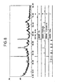
- Fig. 8 is a chart constructed by X-ray identification and analysis of a dried powder of the solid matter that was separated from the oily content of the black viscous lubricating substance. Obviously, the solid matter was chiefly composed of SiO 2 , Fe 3 O 4 , C, graphite and ⁇ -Fe 2 O 3 . Combining this result with the data shown in Fig. 7, one can verify that a mechanochemical reaction occurred in the part of sliding of the shaft 10 against the bush 9.
- Fig. 9 is a set of waveform charts showing the results of measurements with a probe-type roughness meter of the sliding surface profiles of shaft 10 and bush 9 that were disconnected from the slide bearing assembly after the formation of the black viscous lubricating substance was verified.
- Fig. 9a refers to the surface roughness of the shaft 10.
- the sliding interface between the shaft 10 and the bush 9 was improved to a specular state with a surface roughness of 1 ⁇ m or less compared to the value 10 - 12 ⁇ m which was observed before driving the assembly.
- Fig. 9b refers to the surface roughness of the bush 9, showing that the entire sliding surface of the bush 9 was obviously improved to a specular state with a surface roughness of 1 ⁇ m or less. "Galling" which would otherwise occur frequently between the shaft 10 and the bush 9 was totally absent.
- grease is preferably applied to the surfaces of either the shaft or the bush or both before they are assembled.
- grease is applied to the surfaces of the shaft in an amount of 0.001 - 0.1 g/cm 2 , more preferably 0.005 - 0.015 g/cm 2 , most preferably 0.01 g/cm 2 .
- the preassembly application of grease is effective not only in preventing the occurrence of "initial galling" but also in facilitating the subsequent assembling of the shaft and the bush. If grease is applied in an amount less than 0.001 g/cm 2 , it is incapable of preventing the occurrence of "initial galling". If grease is applied in an amount greater than 0.1 g/cm 2 , not only does it interfere with the assembling operation but it will be liquefied after the shaft starts to slide against the bush and may potentially leak out of the bearing assembly.
- the slide bearing assembly is subject to the application of pressures of 800 bar or more to local surface areas on account of "uneven touch" under eccentric loads during the driving of the assembly.
- the completed bearing assembly may be driven to perform sliding motions for a period of 50 - 200 hours, preferably 75 - 150 hours, more preferably 100 - 130 hours, so that the shaft and the bush are "broken in” and, thereafter, grease is supplied over the sliding surfaces of the shaft and the bush in an amount of 0.001 - 0.1 g/cm 2 , preferably 0.005 - 0.015 g/cm 2 , more preferably 0.01 g/cm 2 .
- Fig. 10 is a characteristic diagram showing the relationship among frictional coefficient, temperature and sliding time that demonstrates the effect of injecting grease after the post-completion sliding of the bearing assembly.
- the data shown in Fig. 10 were attained with a bench test apparatus simulating an actual machine and that was operated under the following conditions; pressure, 800 bar; swing angle, 120°; load direction, constant; peripheral speed, 12 rpm.
- a thermocouple alumel/chromel wires
- the frictional heat developing between the shaft and the porous bush was measured in terms of the thermoelectromotive force.
- portion (1) corresponds to the effect achieved by the grease as applied in an amount of 0.01 g/cm 2 prior to assembling and, obviously, the frictional coefficient dropped to 0.03
- portion (2) corresponds to the state where the post-completion sliding caused most of the preliminarily applied grease to be exhausted from the sliding surfaces of the shaft and the bush (i.e., the initial state of the process in which the shaft and the bush were "broken in") and, obviously, the frictional coefficient rose to a value between 0.10 and 0.13
- dashed line (3) shows that the frictional coefficient dropped sharply down to 0.03 as soon as grease was supplied in an amount of 0.01 g/cm 2 over the sliding surfaces of the shaft and the bush when 125 hours passed after the start of the post-completion sliding
- portion (4) is a stable range over which the frictional coefficient was maintained at values of no more than 0.02.
- the slide bearing assembly is, in principle, to be used without refilling of lubricant oils or grease but, as mentioned a few paragraphs ago, certain machines justify the feeding of grease in combination with the high-viscosity lubricant oil.
- the bearing assembly 10 shown in Fig. 1 may be provided with a grease feed hole as indicated by 32 in Fig. 14 which shows a prior art slide bearing assembly.
- Fig. 11 is a partial cross-sectional view showing another example of the slide bearding assembly.
- the bush 9 is provided with a crown 20 at both ends and this is for assuring higher reliability in strength in anticipation of uneven touch between the shaft 10 and the bush 9 which will typically occur on account of their clearance or deformation of the shaft.
- Fig. 12 is a partial cross-sectional view showing yet another example of the slide bearing assembly. If soil, sand, etc. enter the bearing assembly via the O-rings 4 [an example of such intrusion is SiO 2 having a Vickers hardness (Hv) of about 1000], they will exhibit their wearing action to cause wear and other damage to the boss 1 and the brackets 6. In order to avoid this problem, the assembly shown in Fig. 12 is equipped with wear-resisting plates 22 that have a hardness comparable to or higher than that of the soil, sand, etc. These wear-resisting plates 22 are effective not only in improving the tribological characteristics of the bearing assembly and the strength of the bearing per se but also in preventing the occurrence of rattling.
- Hv Vickers hardness
- Fig. 13 is a partial cross-sectional view showing a further example of the slide bearing assembly.
- a high-strength bush 24 made of an iron or a steel (e.g. S45C quenched steel) is interposed between the bush 9 (made of a porous composite sintered alloy) and the boss 1 with a view to compensating for the insufficiency of strength in both end portions of the bush 9.
- the additional bush 24 enables the slide bearing assembly to be used with the application of even higher pressures to the sliding surfaces of the assembly.
- the slide bearing assembly is suitable for use under such conditions that the pressure applied to the sliding surfaces is at least 600 bar.
- the slide bearing assembly is particularly adapted for the use of the invention in slow- and high-pressure applications as exemplified by a bearing in the front part of an excavator, a bearing in the arm of a crane, a bearing in a roller gate on the sluice of a dam, a bearing in a vertically slidable cam on a press mold, a bearing for water wheel guide vanes in hydroelectric power generation and a bearing for an unloader pin on a marine crane.
- Porous oil-filled bearings per se are known to be capable of use without oil refillings and they include, for example, oil-filled bearings made from cast copper alloys and those made from sintered powders.
- the conventional porous oil-filled bearings use lubricant oils of comparatively low viscosities and, under the application of high pressures to the sliding surfaces of the shaft and the bush, the viscosity of the lubricant oil will decrease further on account of the frictional heat from the sliding of the shaft against the bush. This fact, combined with the sliding motions of the shaft against the bush, will cause a substantial amount of the lubricant oil to be exhausted from both the bush and the sliding surfaces in the early stage of operation.
- the interval between oil refillings may be increased to some extent but it certainly is impossible to drive the bearing for a prolonged period of at least several years without any oil refillings.
- the conventional porous oil-filled bearings have been operated with PV values less than 100 bar ⁇ m/s; however, with the recent models of excavators which feature higher efficiencies and greater output powers, it is strongly desired that their front parts be operated with PV values of 100 bar. m/s and more while exhibiting frictional coefficients (p) of no more than 0.15.
- none of the conventional porous bearings which are impregnated with low-viscosity lubricant oils are capable of providing slide bearing assemblies that satisfy these requirements and which yet can be used for a prolonged period without any oil refillings.
- the present invention offers a slide bearing assembly that is used in high-pressure ( ⁇ 600 bar) environments and which yet can be subjected to sliding motions for a prolonged period of at least several, say, five years without any oil refillings.
Description
Claims (11)
- Use of a slide bearing assembly, which comprises a shaft (10) and a bush (9), the bush being formed of a porous iron-base sintered material impregnated with lubricant oil having a viscosity in the range from 2.4 to 15 cm2/s (240 to 1500 cSt) at 40°C, for swinging motions with a pressure of at least 600 bar between the sliding surfaces and a sliding speed of 2 to 5 cm/s, wherein a mechano-chemical reaction product is formed between the sliding surfaces as a result of the sliding of said shaft (10) relative to said bush (9).
- The use of the bearing assembly according to claim 1, wherein said shaft (10) is made of an iron or a steel that has been carburised, rf quenched and nitrided, followed by the formation of a conversion coating or sulfurising to modify the surface thereof.
- The use of the bearing assembly according to claim 1 or 2, wherein said bush (9) is made of a composite sintered alloy of iron and copper powder having a porosity of 5 to 30 %, wherein the pores (14) in said bush communicate with one another, and wherein said bush has its surface modified by carburisation, nitriding or sulfonitriding.
- The use of the bearing assembly according to any preceding claim, wherein said lubricant oil contains particles of at least one solid lubricant selected from among MoS2, WS2, hexagonal BN and graphite, said particles having sizes of no more than 500 µm.
- The use of the bearing assembly according to any preceding claim, wherein an oil shield member (12) is provided in contact with either end of said bush (9).
- The use of the bearing assembly according to claim 5, wherein said oil shield member (12) is formed of a soft, elastic and oil-absorbing material, preferably of non-woven fabric, woven fabric, porous elastic plastic material, sponge, asbestos or felt.
- The use of the bearing assembly according to any preceding claim, wherein said bush is provided with crown portions (20).
- The use of the bearing assembly according to any preceding claim, including a bracket (6) positioned at either end of a boss (1), having the bush (9) provided in contact with the inner periphery thereof, wherein a very hard wear-resistant plate is provided between the sliding surfaces of said boss and each of said brackets.
- The use of the bearing assembly according to any preceding claim, including a boss (1), and two concentric bushes (9, 24) within said boss, one (24) of which is a high-strength bush provided radially outward and positioned in contact with the inner periphery of said boss (1) while the other (9) is a porous composite sintered alloy bush provided radially inward of said high-strength bush (24).
- The use of the bearing assembly according to any preceding claim with a pressure of at least 800 bar being applied to the sliding surfaces, wherein either the shaft (10) or the bush (9) is coated with grease in an amount of 0.001 - 0.1 g/cm2, preferably 0.005 to 0.015 g/cm2, and even more preferred 0.01 g/cm2 the shaft is then inserted into the bush for assembling, followed by sliding the shaft against the bush for a period of 50 - 200 h, preferably 75 - 150 h, and even more preferred 100 - 130 h, and wherein grease is subsequently supplied over the sliding surfaces of the shaft and the bush in an amount of 0.001 - 0.01 g/cm2, preferably 0.005 to 0.015 g/cm2, and even more preferred 0.01 g/cm2.
- The use of the bearing assembly according to any preceding claim in the front part of an excavator, in the arm of a crane, in a roller gate on the sluice of a dam, in a vertically slidable cam on a press mould, for water wheel guide vanes in hydroelectric power generation, or for an unloader pin on a marine crane.
Priority Applications (1)
| Application Number | Priority Date | Filing Date | Title |
|---|---|---|---|
| EP99105555A EP0926367A1 (en) | 1993-10-22 | 1994-10-19 | Slide bearing |
Applications Claiming Priority (9)
| Application Number | Priority Date | Filing Date | Title |
|---|---|---|---|
| JP287527/93 | 1993-10-22 | ||
| JP28752793 | 1993-10-22 | ||
| JP28752793 | 1993-10-22 | ||
| JP210493/94 | 1994-08-11 | ||
| JP21049394 | 1994-08-11 | ||
| JP21049394 | 1994-08-11 | ||
| JP6256095A JP2832800B2 (en) | 1993-10-22 | 1994-09-27 | Plain bearing assembly |
| JP25609594 | 1994-09-27 | ||
| JP256095/94 | 1994-09-27 |
Related Child Applications (1)
| Application Number | Title | Priority Date | Filing Date |
|---|---|---|---|
| EP99105555.9 Division-Into | 1999-03-18 |
Publications (3)
| Publication Number | Publication Date |
|---|---|
| EP0655562A2 EP0655562A2 (en) | 1995-05-31 |
| EP0655562A3 EP0655562A3 (en) | 1996-08-14 |
| EP0655562B1 true EP0655562B1 (en) | 2004-05-26 |
Family
ID=27329127
Family Applications (2)
| Application Number | Title | Priority Date | Filing Date |
|---|---|---|---|
| EP99105555A Withdrawn EP0926367A1 (en) | 1993-10-22 | 1994-10-19 | Slide bearing |
| EP94116494A Expired - Lifetime EP0655562B1 (en) | 1993-10-22 | 1994-10-19 | Slide bearing assembly |
Family Applications Before (1)
| Application Number | Title | Priority Date | Filing Date |
|---|---|---|---|
| EP99105555A Withdrawn EP0926367A1 (en) | 1993-10-22 | 1994-10-19 | Slide bearing |
Country Status (6)
| Country | Link |
|---|---|
| US (2) | US5490730A (en) |
| EP (2) | EP0926367A1 (en) |
| JP (1) | JP2832800B2 (en) |
| KR (1) | KR100261369B1 (en) |
| CN (2) | CN1062342C (en) |
| DE (1) | DE69433807T2 (en) |
Cited By (1)
| Publication number | Priority date | Publication date | Assignee | Title |
|---|---|---|---|---|
| DE102013012542A1 (en) * | 2013-07-29 | 2015-01-29 | Liebherr-Werk Bischofshofen Gmbh | bearing arrangement |
Families Citing this family (58)
| Publication number | Priority date | Publication date | Assignee | Title |
|---|---|---|---|---|
| JPH1082423A (en) * | 1993-10-22 | 1998-03-31 | Hitachi Constr Mach Co Ltd | Sliding bearing |
| JPH08128505A (en) * | 1994-10-28 | 1996-05-21 | Jatco Corp | Washer for carrier of planet gear |
| CN1072333C (en) * | 1995-07-14 | 2001-10-03 | 株式会社Ntn | Bearing device |
| KR100224000B1 (en) * | 1996-08-19 | 1999-10-15 | 이형도 | Sintered porous bearing |
| US5941646A (en) * | 1996-12-25 | 1999-08-24 | Ntn Corporation | Hydrodynamic type porous oil-impregnated bearing and bearing device |
| JP3168538B2 (en) * | 1997-04-19 | 2001-05-21 | チャン リー ウー | Sliding bearing and method of manufacturing the same |
| DE19738919C1 (en) * | 1997-09-05 | 1999-04-29 | Maxon Motor Gmbh | Process for manufacturing a plain bearing and plain bearing |
| JPH11153091A (en) * | 1997-09-18 | 1999-06-08 | Matsushita Electric Ind Co Ltd | Slide member and refrigeration compressor using the slide member |
| TW455649B (en) * | 1997-11-25 | 2001-09-21 | Matsushita Electric Ind Co Ltd | A bearing device comprising a slide member and a holding member, both made of porous sintered metal impregnated with lubricating oil |
| US6082495A (en) * | 1998-02-25 | 2000-07-04 | Copeland Corporation | Scroll compressor bearing lubrication |
| JPH11280419A (en) * | 1998-03-31 | 1999-10-12 | Sumitomo Electric Ind Ltd | Combination body of shim and cam |
| ES2161127B1 (en) * | 1999-03-16 | 2002-09-01 | Castellon Melchor Daumal | TELESCOPIC TREE FOR STEERING COLUMNS IN CAR VEHICLES WITH SLIDING SYSTEM WITH LOAD CONTROL. |
| CA2337778A1 (en) * | 2000-02-17 | 2001-08-17 | Mark H. Eisenberg | Axle bolt |
| JP2001234244A (en) * | 2000-02-28 | 2001-08-28 | Toshiba Corp | Sliding member for diesel engine |
| JP2002181050A (en) * | 2000-03-16 | 2002-06-26 | Nsk Ltd | Rolling sliding member, manufacturing method therefor and rolling sliding unit |
| WO2001088395A1 (en) * | 2000-05-19 | 2001-11-22 | Hitachi Construction Machinery Co., Ltd. | Bearing device |
| US6783129B2 (en) | 2001-03-13 | 2004-08-31 | Hitachi Construction Machinery Co., Ltd. | Sealing device |
| US6693990B1 (en) * | 2001-05-14 | 2004-02-17 | Varian Medical Systems Technologies, Inc. | Low thermal resistance bearing assembly for x-ray device |
| JP4644981B2 (en) * | 2001-07-06 | 2011-03-09 | キャタピラージャパン株式会社 | Pin joint structure |
| KR100877139B1 (en) * | 2001-08-22 | 2009-01-07 | 가부시키가이샤 고마츠 세이사꾸쇼 | Crawler Belt, Pin, Bush and Method for Manufacturing Crawler Belt |
| JP4282284B2 (en) | 2001-08-22 | 2009-06-17 | 株式会社小松製作所 | Track |
| KR100993158B1 (en) * | 2001-09-26 | 2010-11-09 | 가부시키가이샤 고마쓰 세이사쿠쇼 | Connecting mechanism |
| JP4204233B2 (en) * | 2002-01-30 | 2009-01-07 | 日立粉末冶金株式会社 | Sintered oil-impregnated plain bearings and construction machinery hydraulic excavators or cranes |
| DE10212056A1 (en) * | 2002-03-19 | 2003-10-02 | Sms Demag Ag | Leading role for a continuous caster |
| US7004635B1 (en) | 2002-05-17 | 2006-02-28 | Varian Medical Systems, Inc. | Lubricated ball bearings |
| US6751292B2 (en) | 2002-08-19 | 2004-06-15 | Varian Medical Systems, Inc. | X-ray tube rotor assembly having augmented heat transfer capability |
| JP2004100812A (en) * | 2002-09-09 | 2004-04-02 | Hitachi Constr Mach Co Ltd | Bearing device |
| JP4289926B2 (en) | 2003-05-26 | 2009-07-01 | 株式会社小松製作所 | Sliding material, sliding member, sliding component, and apparatus to which the sliding material is applied |
| JP4168844B2 (en) * | 2003-06-10 | 2008-10-22 | 松下電器産業株式会社 | Refrigerant pump and cooling device |
| JPWO2005019664A1 (en) * | 2003-08-25 | 2006-10-19 | 日立建機株式会社 | Slide bearing assembly and slide bearing |
| KR101021995B1 (en) | 2004-10-29 | 2011-03-16 | 히다치 겡키 가부시키 가이샤 | Grease for sliding bearing |
| TW200717976A (en) * | 2005-10-28 | 2007-05-01 | Sunonwealth Electr Mach Ind Co | Structure of bearing |
| JP2007321803A (en) * | 2006-05-30 | 2007-12-13 | Ntn Corp | Torque limiter |
| KR101240051B1 (en) | 2006-11-20 | 2013-03-06 | 두산인프라코어 주식회사 | Bearing for improving a consume resisting and this manufacturing process |
| JP4480748B2 (en) * | 2007-09-13 | 2010-06-16 | 株式会社椿本チエイン | Lubricating oil and oil-free chain |
| JP2009074572A (en) * | 2007-09-19 | 2009-04-09 | Panasonic Corp | Fluid bearing device and information recording regeneration processing apparatus equipped with the same |
| KR100932544B1 (en) * | 2007-12-19 | 2009-12-17 | 주식회사 티엠시 | Sintered bearing and its manufacturing method |
| JP4966217B2 (en) * | 2008-01-31 | 2012-07-04 | 株式会社クボタ | Riding paddy field machine |
| KR101533458B1 (en) | 2008-10-23 | 2015-07-03 | 두산인프라코어 주식회사 | Sliding bearing having improved consume resistivity and manufacturing method thereof |
| BRPI0924025B1 (en) * | 2008-12-05 | 2021-01-19 | Doosan Infracore Co., Ltd. | slide bearing and slide bearing assembly |
| KR101569236B1 (en) | 2008-12-19 | 2015-11-13 | 두산인프라코어 주식회사 | Sintered bush |
| KR101747965B1 (en) * | 2009-12-22 | 2017-06-15 | 두산인프라코어 주식회사 | Sliding bearing and sliding bearing assembly |
| JP5752385B2 (en) * | 2010-03-30 | 2015-07-22 | Ntn株式会社 | Rolling bearing device |
| DE202010006089U1 (en) * | 2010-04-27 | 2011-09-01 | Brose Fahrzeugteile GmbH & Co. Kommanditgesellschaft, Würzburg | bearings |
| BRPI1005091A2 (en) * | 2010-12-03 | 2013-03-26 | Whirlpool Sa | tribological pair and surface treatment process in tribological pairs |
| JP5535093B2 (en) | 2011-01-07 | 2014-07-02 | 日立建機株式会社 | Sliding bearing and construction machine provided with the same |
| CN103174735A (en) * | 2011-12-20 | 2013-06-26 | 西安奥奈特固体润滑工程学研究有限公司 | Excavator boom pin roll system |
| CN102560175B (en) * | 2011-12-28 | 2014-09-03 | 成都易态科技有限公司 | Method for adjusting pore diameter of metal porous material and pore structure of metal porous material |
| CN104527212A (en) * | 2014-12-24 | 2015-04-22 | 南昌印钞有限公司 | Banknote printing gravure wiping roller with graphite copper sleeves adopted for spherical bearings |
| CN105370887B (en) * | 2015-11-04 | 2017-07-14 | 西北工业大学 | A kind of quiet dynamic compound sealing structure and method for rotary machine rotor |
| US10024350B2 (en) | 2016-01-20 | 2018-07-17 | Caterpillar Inc. | Seal system for dry lube pin joints |
| GB201604863D0 (en) * | 2016-03-22 | 2016-05-04 | Esr Technology Ltd | Bearing-support housing/shaft |
| CN107120433A (en) * | 2017-04-21 | 2017-09-01 | 邱建华 | The press-roller device and preparation method of a kind of repeatable lubrication |
| CN108130501B (en) * | 2017-12-14 | 2020-02-21 | 中国人民解放军陆军装甲兵学院 | Preparation method of steel backing copper-based bearing copper coating |
| JP7090870B2 (en) * | 2017-12-26 | 2022-06-27 | 東京パーツ工業株式会社 | motor |
| KR102054868B1 (en) * | 2019-04-24 | 2019-12-16 | 주식회사 동국알앤에스 | Electrode anti-oxidation method and impregnating liquid |
| DE102021109854B3 (en) | 2021-04-19 | 2022-07-14 | Leibniz-Institut für Verbundwerkstoffe GmbH | Procedure for the design and operational prediction of dry-running and insufficiently lubricated machine elements with sliding function |
| CN116123211B (en) * | 2023-02-22 | 2023-08-01 | 南京林业大学 | High-speed rolling bearing with self-adaptive sealing and reinforced cooling structure |
Family Cites Families (9)
| Publication number | Priority date | Publication date | Assignee | Title |
|---|---|---|---|---|
| DD1216A (en) * | ||||
| DE1216C (en) * | 1877-10-20 | A. THIELE, Architekt, und GOETJES & .SCHULZE in Bautzen | Brick kiln | |
| US2266379A (en) * | 1939-01-07 | 1941-12-16 | Standard Oil Co California | Extreme pressure lubrication |
| DE1056880B (en) * | 1957-09-18 | 1959-05-06 | Licentia Gmbh | Bearing material |
| FR1409876A (en) * | 1964-07-22 | 1965-09-03 | Berliet Automobiles | Surface treatment to jointly improve friction and sealing |
| DE3001115A1 (en) * | 1980-01-14 | 1981-07-16 | Gerätewerk Lahr GmbH, 7630 Lahr | SELF-LUBRICATING SLIDING BEARING FOR A SHAFT, ESPECIALLY A TURNTABLE SHAFT OF A TURNTABLE |
| US4952328A (en) * | 1988-05-27 | 1990-08-28 | The Lubrizol Corporation | Lubricating oil compositions |
| US4981602A (en) * | 1988-06-13 | 1991-01-01 | The Lubrizol Corporation | Lubricating oil compositions and concentrates |
| US5401105A (en) * | 1992-12-28 | 1995-03-28 | Nsk Ltd. | Ball bearing and method for producing a cage of the ball bearing |
-
1994
- 1994-09-27 JP JP6256095A patent/JP2832800B2/en not_active Expired - Lifetime
- 1994-10-19 EP EP99105555A patent/EP0926367A1/en not_active Withdrawn
- 1994-10-19 DE DE69433807T patent/DE69433807T2/en not_active Expired - Lifetime
- 1994-10-19 EP EP94116494A patent/EP0655562B1/en not_active Expired - Lifetime
- 1994-10-20 US US08/326,334 patent/US5490730A/en not_active Ceased
- 1994-10-21 KR KR1019940026920A patent/KR100261369B1/en not_active IP Right Cessation
- 1994-10-22 CN CN94119679A patent/CN1062342C/en not_active Expired - Lifetime
-
1998
- 1998-02-02 US US09/017,319 patent/USRE36405E/en not_active Expired - Lifetime
-
2000
- 2000-02-24 CN CNB001036343A patent/CN1250887C/en not_active Expired - Lifetime
Cited By (1)
| Publication number | Priority date | Publication date | Assignee | Title |
|---|---|---|---|---|
| DE102013012542A1 (en) * | 2013-07-29 | 2015-01-29 | Liebherr-Werk Bischofshofen Gmbh | bearing arrangement |
Also Published As
| Publication number | Publication date |
|---|---|
| EP0655562A2 (en) | 1995-05-31 |
| JP2832800B2 (en) | 1998-12-09 |
| CN1290822A (en) | 2001-04-11 |
| EP0655562A3 (en) | 1996-08-14 |
| US5490730A (en) | 1996-02-13 |
| DE69433807T2 (en) | 2005-08-04 |
| CN1106900A (en) | 1995-08-16 |
| USRE36405E (en) | 1999-11-23 |
| CN1062342C (en) | 2001-02-21 |
| JPH08105444A (en) | 1996-04-23 |
| EP0926367A1 (en) | 1999-06-30 |
| KR100261369B1 (en) | 2000-07-01 |
| DE69433807D1 (en) | 2004-07-01 |
| CN1250887C (en) | 2006-04-12 |
Similar Documents
| Publication | Publication Date | Title |
|---|---|---|
| EP0655562B1 (en) | Slide bearing assembly | |
| EP1659303A1 (en) | Sliding bearing assembly and sliding bearing | |
| EP2312174B1 (en) | Slide bearing with grease | |
| US20030150140A1 (en) | Coupling device for equipment implement | |
| JPS59200087A (en) | Hydraulic type pump for carrier medium of low viscosity | |
| JP2004360731A (en) | Sliding bearing, and work machine connecting device using the same | |
| JPH1082423A (en) | Sliding bearing | |
| JPH10246231A (en) | Sliding bearing assembly | |
| JP4451276B2 (en) | Grease for slide bearing | |
| KR100244584B1 (en) | Sliding bearing | |
| JP2005069365A (en) | Plain bearing assembly and plain bearing | |
| JPH11336763A (en) | Sliding bearing device for bush and construction equipment, and manufacture of bush | |
| Marappan et al. | Performance studies on Sursulf-treated plain carbon steel journal bearings under mixed lubrication conditions | |
| EP2782986A1 (en) | A sealing system, an industrial robot with a sealing system, and a method for providing a sealing surface | |
| Rao et al. | Performance studies on treated steels as substitutes for conventional bearing materials | |
| JPH0372682B2 (en) | ||
| JP4451277B2 (en) | Grease for slide bearing | |
| Al-Samarai et al. | Lubrication and Lubricants | |
| Totten | Glossary of Terms | |
| Midgley et al. | Bearing Metals; Novel Bearing Materials; Glands and Seals; Solid Lubricants; Surface Treatments | |
| Marappan et al. | Performance studies on Tufftrided plain carbon steel journal bearings under mixed lubrication conditions | |
| Barwell | Proceedings of the JSLE international tribology conference, Tokyo, Japan, July 8–10, 1985: Edited by Y. Tamai; published by Elsevier, Amsterdam, 1985; 3 volumes, 1230 pp.; price, US $277.75, Dfl. 750.00; ISBN 0-444-99537-4 | |
| Woodley | The mechanisms of wear: 8th May, 1978, London, UK | |
| Thorp | Tribology: A revolution in the science of friction, lubrication and wear | |
| AU4873199A (en) | Grease-lubricated sliding guiding members having a low coefficient of friction and an improved lifetime |
Legal Events
| Date | Code | Title | Description |
|---|---|---|---|
| PUAI | Public reference made under article 153(3) epc to a published international application that has entered the european phase |
Free format text: ORIGINAL CODE: 0009012 |
|
| AK | Designated contracting states |
Kind code of ref document: A2 Designated state(s): DE FR GB IT SE |
|
| PUAL | Search report despatched |
Free format text: ORIGINAL CODE: 0009013 |
|
| AK | Designated contracting states |
Kind code of ref document: A3 Designated state(s): DE FR GB IT SE |
|
| 17P | Request for examination filed |
Effective date: 19970127 |
|
| 17Q | First examination report despatched |
Effective date: 19980817 |
|
| GRAP | Despatch of communication of intention to grant a patent |
Free format text: ORIGINAL CODE: EPIDOSNIGR1 |
|
| GRAS | Grant fee paid |
Free format text: ORIGINAL CODE: EPIDOSNIGR3 |
|
| GRAA | (expected) grant |
Free format text: ORIGINAL CODE: 0009210 |
|
| AK | Designated contracting states |
Kind code of ref document: B1 Designated state(s): DE FR GB IT SE |
|
| PG25 | Lapsed in a contracting state [announced via postgrant information from national office to epo] |
Ref country code: FR Free format text: LAPSE BECAUSE OF NON-PAYMENT OF DUE FEES Effective date: 20040526 |
|
| REG | Reference to a national code |
Ref country code: GB Ref legal event code: FG4D |
|
| REF | Corresponds to: |
Ref document number: 69433807 Country of ref document: DE Date of ref document: 20040701 Kind code of ref document: P |
|
| PG25 | Lapsed in a contracting state [announced via postgrant information from national office to epo] |
Ref country code: SE Free format text: LAPSE BECAUSE OF FAILURE TO SUBMIT A TRANSLATION OF THE DESCRIPTION OR TO PAY THE FEE WITHIN THE PRESCRIBED TIME-LIMIT Effective date: 20040826 |
|
| PLBE | No opposition filed within time limit |
Free format text: ORIGINAL CODE: 0009261 |
|
| STAA | Information on the status of an ep patent application or granted ep patent |
Free format text: STATUS: NO OPPOSITION FILED WITHIN TIME LIMIT |
|
| 26N | No opposition filed |
Effective date: 20050301 |
|
| EN | Fr: translation not filed | ||
| PGFP | Annual fee paid to national office [announced via postgrant information from national office to epo] |
Ref country code: GB Payment date: 20131016 Year of fee payment: 20 Ref country code: DE Payment date: 20131016 Year of fee payment: 20 |
|
| PGFP | Annual fee paid to national office [announced via postgrant information from national office to epo] |
Ref country code: IT Payment date: 20131018 Year of fee payment: 20 |
|
| REG | Reference to a national code |
Ref country code: DE Ref legal event code: R071 Ref document number: 69433807 Country of ref document: DE |
|
| REG | Reference to a national code |
Ref country code: GB Ref legal event code: PE20 Expiry date: 20141018 |
|
| PG25 | Lapsed in a contracting state [announced via postgrant information from national office to epo] |
Ref country code: GB Free format text: LAPSE BECAUSE OF EXPIRATION OF PROTECTION Effective date: 20141018 |