EP0655423B1 - Method of making infrared crystalline fiber and product - Google Patents
Method of making infrared crystalline fiber and product Download PDFInfo
- Publication number
- EP0655423B1 EP0655423B1 EP93118812A EP93118812A EP0655423B1 EP 0655423 B1 EP0655423 B1 EP 0655423B1 EP 93118812 A EP93118812 A EP 93118812A EP 93118812 A EP93118812 A EP 93118812A EP 0655423 B1 EP0655423 B1 EP 0655423B1
- Authority
- EP
- European Patent Office
- Prior art keywords
- fiber
- extrusion
- preform
- core
- silver halide
- Prior art date
- Legal status (The legal status is an assumption and is not a legal conclusion. Google has not performed a legal analysis and makes no representation as to the accuracy of the status listed.)
- Expired - Lifetime
Links
- 239000000835 fiber Substances 0.000 title claims description 82
- 238000004519 manufacturing process Methods 0.000 title description 6
- 238000001125 extrusion Methods 0.000 claims description 43
- 238000000034 method Methods 0.000 claims description 38
- 230000008569 process Effects 0.000 claims description 25
- 229910052709 silver Inorganic materials 0.000 claims description 23
- 239000004332 silver Substances 0.000 claims description 23
- 238000005253 cladding Methods 0.000 claims description 22
- -1 silver halide Chemical class 0.000 claims description 22
- 239000000463 material Substances 0.000 claims description 14
- 230000003287 optical effect Effects 0.000 claims description 11
- 229920000642 polymer Polymers 0.000 claims description 8
- 230000003247 decreasing effect Effects 0.000 claims description 5
- 239000007788 liquid Substances 0.000 claims description 5
- 239000013307 optical fiber Substances 0.000 claims description 4
- 230000007423 decrease Effects 0.000 claims description 3
- 239000002657 fibrous material Substances 0.000 claims description 3
- 239000011261 inert gas Substances 0.000 claims description 2
- 230000006835 compression Effects 0.000 claims 1
- 238000007906 compression Methods 0.000 claims 1
- 230000001747 exhibiting effect Effects 0.000 claims 1
- 239000013078 crystal Substances 0.000 description 9
- 230000007547 defect Effects 0.000 description 9
- 230000005540 biological transmission Effects 0.000 description 8
- 229910052751 metal Inorganic materials 0.000 description 6
- 239000002184 metal Substances 0.000 description 6
- 230000005855 radiation Effects 0.000 description 5
- 239000006104 solid solution Substances 0.000 description 5
- 230000015572 biosynthetic process Effects 0.000 description 4
- 238000011109 contamination Methods 0.000 description 4
- 239000007789 gas Substances 0.000 description 4
- 239000000314 lubricant Substances 0.000 description 4
- 150000001768 cations Chemical class 0.000 description 3
- 238000009792 diffusion process Methods 0.000 description 3
- 239000002019 doping agent Substances 0.000 description 3
- 239000000203 mixture Substances 0.000 description 3
- XKRFYHLGVUSROY-UHFFFAOYSA-N Argon Chemical compound [Ar] XKRFYHLGVUSROY-UHFFFAOYSA-N 0.000 description 2
- XUIMIQQOPSSXEZ-UHFFFAOYSA-N Silicon Chemical compound [Si] XUIMIQQOPSSXEZ-UHFFFAOYSA-N 0.000 description 2
- BQCADISMDOOEFD-UHFFFAOYSA-N Silver Chemical compound [Ag] BQCADISMDOOEFD-UHFFFAOYSA-N 0.000 description 2
- 238000005452 bending Methods 0.000 description 2
- 230000008901 benefit Effects 0.000 description 2
- 229910052794 bromium Inorganic materials 0.000 description 2
- 229910052793 cadmium Inorganic materials 0.000 description 2
- 229910052801 chlorine Inorganic materials 0.000 description 2
- 239000000460 chlorine Substances 0.000 description 2
- 239000011248 coating agent Substances 0.000 description 2
- 238000000576 coating method Methods 0.000 description 2
- 239000000084 colloidal system Substances 0.000 description 2
- 239000012530 fluid Substances 0.000 description 2
- 239000012535 impurity Substances 0.000 description 2
- 229910052740 iodine Inorganic materials 0.000 description 2
- 229910052745 lead Inorganic materials 0.000 description 2
- 239000011159 matrix material Substances 0.000 description 2
- 229910052753 mercury Inorganic materials 0.000 description 2
- 239000003921 oil Substances 0.000 description 2
- 239000004033 plastic Substances 0.000 description 2
- 229920003023 plastic Polymers 0.000 description 2
- 238000003825 pressing Methods 0.000 description 2
- 238000001953 recrystallisation Methods 0.000 description 2
- 229910052710 silicon Inorganic materials 0.000 description 2
- 239000010703 silicon Substances 0.000 description 2
- ADZWSOLPGZMUMY-UHFFFAOYSA-M silver bromide Chemical compound [Ag]Br ADZWSOLPGZMUMY-UHFFFAOYSA-M 0.000 description 2
- HKZLPVFGJNLROG-UHFFFAOYSA-M silver monochloride Chemical compound [Cl-].[Ag+] HKZLPVFGJNLROG-UHFFFAOYSA-M 0.000 description 2
- 230000000087 stabilizing effect Effects 0.000 description 2
- ZCYVEMRRCGMTRW-UHFFFAOYSA-N 7553-56-2 Chemical compound [I] ZCYVEMRRCGMTRW-UHFFFAOYSA-N 0.000 description 1
- WKBOTKDWSSQWDR-UHFFFAOYSA-N Bromine atom Chemical compound [Br] WKBOTKDWSSQWDR-UHFFFAOYSA-N 0.000 description 1
- ZAMOUSCENKQFHK-UHFFFAOYSA-N Chlorine atom Chemical compound [Cl] ZAMOUSCENKQFHK-UHFFFAOYSA-N 0.000 description 1
- 238000004566 IR spectroscopy Methods 0.000 description 1
- 239000004698 Polyethylene Substances 0.000 description 1
- 229910021607 Silver chloride Inorganic materials 0.000 description 1
- FOIXSVOLVBLSDH-UHFFFAOYSA-N Silver ion Chemical compound [Ag+] FOIXSVOLVBLSDH-UHFFFAOYSA-N 0.000 description 1
- 238000010521 absorption reaction Methods 0.000 description 1
- 229910052783 alkali metal Inorganic materials 0.000 description 1
- 150000001340 alkali metals Chemical class 0.000 description 1
- 229910052786 argon Inorganic materials 0.000 description 1
- 229910052788 barium Inorganic materials 0.000 description 1
- 230000004888 barrier function Effects 0.000 description 1
- 239000002585 base Substances 0.000 description 1
- GDTBXPJZTBHREO-UHFFFAOYSA-N bromine Substances BrBr GDTBXPJZTBHREO-UHFFFAOYSA-N 0.000 description 1
- 229910052792 caesium Inorganic materials 0.000 description 1
- 229910052791 calcium Inorganic materials 0.000 description 1
- 230000000052 comparative effect Effects 0.000 description 1
- 150000001875 compounds Chemical class 0.000 description 1
- 238000007796 conventional method Methods 0.000 description 1
- 238000001816 cooling Methods 0.000 description 1
- 229910052802 copper Inorganic materials 0.000 description 1
- 239000010949 copper Substances 0.000 description 1
- 230000007812 deficiency Effects 0.000 description 1
- 238000009826 distribution Methods 0.000 description 1
- 230000000694 effects Effects 0.000 description 1
- 230000007613 environmental effect Effects 0.000 description 1
- 230000003631 expected effect Effects 0.000 description 1
- 230000002349 favourable effect Effects 0.000 description 1
- 238000007380 fibre production Methods 0.000 description 1
- 238000005755 formation reaction Methods 0.000 description 1
- 150000004820 halides Chemical class 0.000 description 1
- 238000003780 insertion Methods 0.000 description 1
- 230000037431 insertion Effects 0.000 description 1
- 238000011835 investigation Methods 0.000 description 1
- 239000011630 iodine Substances 0.000 description 1
- 229910052744 lithium Inorganic materials 0.000 description 1
- 238000005461 lubrication Methods 0.000 description 1
- 229910052749 magnesium Inorganic materials 0.000 description 1
- 230000007246 mechanism Effects 0.000 description 1
- 239000000155 melt Substances 0.000 description 1
- 150000002736 metal compounds Chemical class 0.000 description 1
- 238000012986 modification Methods 0.000 description 1
- 230000004048 modification Effects 0.000 description 1
- 238000005191 phase separation Methods 0.000 description 1
- 238000001782 photodegradation Methods 0.000 description 1
- 229920000573 polyethylene Polymers 0.000 description 1
- 230000008092 positive effect Effects 0.000 description 1
- 229910052700 potassium Inorganic materials 0.000 description 1
- 238000012545 processing Methods 0.000 description 1
- 239000011253 protective coating Substances 0.000 description 1
- 230000001681 protective effect Effects 0.000 description 1
- 238000005096 rolling process Methods 0.000 description 1
- 229910052701 rubidium Inorganic materials 0.000 description 1
- 229910052708 sodium Inorganic materials 0.000 description 1
- 238000005728 strengthening Methods 0.000 description 1
- 229910052712 strontium Inorganic materials 0.000 description 1
- 230000007704 transition Effects 0.000 description 1
- 229910052727 yttrium Inorganic materials 0.000 description 1
Images


Classifications
-
- G—PHYSICS
- G02—OPTICS
- G02B—OPTICAL ELEMENTS, SYSTEMS OR APPARATUS
- G02B6/00—Light guides; Structural details of arrangements comprising light guides and other optical elements, e.g. couplings
- G02B6/02—Optical fibres with cladding with or without a coating
- G02B6/02033—Core or cladding made from organic material, e.g. polymeric material
-
- C—CHEMISTRY; METALLURGY
- C03—GLASS; MINERAL OR SLAG WOOL
- C03B—MANUFACTURE, SHAPING, OR SUPPLEMENTARY PROCESSES
- C03B37/00—Manufacture or treatment of flakes, fibres, or filaments from softened glass, minerals, or slags
- C03B37/01—Manufacture of glass fibres or filaments
- C03B37/02—Manufacture of glass fibres or filaments by drawing or extruding, e.g. direct drawing of molten glass from nozzles; Cooling fins therefor
- C03B37/022—Manufacture of glass fibres or filaments by drawing or extruding, e.g. direct drawing of molten glass from nozzles; Cooling fins therefor from molten glass in which the resultant product consists of different sorts of glass or is characterised by shape, e.g. hollow fibres, undulated fibres, fibres presenting a rough surface
- C03B37/023—Fibres composed of different sorts of glass, e.g. glass optical fibres, made by the double crucible technique
-
- C—CHEMISTRY; METALLURGY
- C03—GLASS; MINERAL OR SLAG WOOL
- C03C—CHEMICAL COMPOSITION OF GLASSES, GLAZES OR VITREOUS ENAMELS; SURFACE TREATMENT OF GLASS; SURFACE TREATMENT OF FIBRES OR FILAMENTS MADE FROM GLASS, MINERALS OR SLAGS; JOINING GLASS TO GLASS OR OTHER MATERIALS
- C03C3/00—Glass compositions
- C03C3/32—Non-oxide glass compositions, e.g. binary or ternary halides, sulfides or nitrides of germanium, selenium or tellurium
-
- C—CHEMISTRY; METALLURGY
- C30—CRYSTAL GROWTH
- C30B—SINGLE-CRYSTAL GROWTH; UNIDIRECTIONAL SOLIDIFICATION OF EUTECTIC MATERIAL OR UNIDIRECTIONAL DEMIXING OF EUTECTOID MATERIAL; REFINING BY ZONE-MELTING OF MATERIAL; PRODUCTION OF A HOMOGENEOUS POLYCRYSTALLINE MATERIAL WITH DEFINED STRUCTURE; SINGLE CRYSTALS OR HOMOGENEOUS POLYCRYSTALLINE MATERIAL WITH DEFINED STRUCTURE; AFTER-TREATMENT OF SINGLE CRYSTALS OR A HOMOGENEOUS POLYCRYSTALLINE MATERIAL WITH DEFINED STRUCTURE; APPARATUS THEREFOR
- C30B29/00—Single crystals or homogeneous polycrystalline material with defined structure characterised by the material or by their shape
- C30B29/10—Inorganic compounds or compositions
- C30B29/12—Halides
-
- C—CHEMISTRY; METALLURGY
- C30—CRYSTAL GROWTH
- C30B—SINGLE-CRYSTAL GROWTH; UNIDIRECTIONAL SOLIDIFICATION OF EUTECTIC MATERIAL OR UNIDIRECTIONAL DEMIXING OF EUTECTOID MATERIAL; REFINING BY ZONE-MELTING OF MATERIAL; PRODUCTION OF A HOMOGENEOUS POLYCRYSTALLINE MATERIAL WITH DEFINED STRUCTURE; SINGLE CRYSTALS OR HOMOGENEOUS POLYCRYSTALLINE MATERIAL WITH DEFINED STRUCTURE; AFTER-TREATMENT OF SINGLE CRYSTALS OR A HOMOGENEOUS POLYCRYSTALLINE MATERIAL WITH DEFINED STRUCTURE; APPARATUS THEREFOR
- C30B33/00—After-treatment of single crystals or homogeneous polycrystalline material with defined structure
-
- G—PHYSICS
- G02—OPTICS
- G02B—OPTICAL ELEMENTS, SYSTEMS OR APPARATUS
- G02B6/00—Light guides; Structural details of arrangements comprising light guides and other optical elements, e.g. couplings
- G02B6/10—Light guides; Structural details of arrangements comprising light guides and other optical elements, e.g. couplings of the optical waveguide type
- G02B6/102—Light guides; Structural details of arrangements comprising light guides and other optical elements, e.g. couplings of the optical waveguide type for infrared and ultraviolet radiation
-
- C—CHEMISTRY; METALLURGY
- C03—GLASS; MINERAL OR SLAG WOOL
- C03B—MANUFACTURE, SHAPING, OR SUPPLEMENTARY PROCESSES
- C03B2201/00—Type of glass produced
- C03B2201/80—Non-oxide glasses or glass-type compositions
- C03B2201/84—Halide glasses other than fluoride glasses, i.e. Cl, Br or I glasses, e.g. AgCl-AgBr "glass"
Definitions
- the present invention relates to a method of making silver halide crystalline fibers capable of transmitting infrared light and to the fiber product made by the process.
- Infrared fibers are of technical interest for the transmission fo low power radiation signals from the environment, such as heat radiation to infrared tectors. They are of further interest in remote infrared spectroscopy and in the transmission of laser energy from CO 2 and CO lasers in particular.
- Silver halide fibers consisting of silver chloride (AgCl), silver bromide (AgBr), and their solid solutions (AgCl x Br 1-x ) show promising properties for the transmission of middle infrared radiation.
- the fibers can either be bare core fibers, with gas functioning as the lower refractive index, total reflecting medium or polymer coated fibers or core/clad fibers where the cladding contains more AgCl for total internal reflection.
- JP 58 043 404 A discloses a process with the features of the preamble of claims 1-3. From JP 57 208 506 A it is known to produce a crystalline halide optical fiber having larger grain size at the core center part and with crystal grain size decreasing sucessively to the external circumference. From JP 02 302 705 A it is known to place assistant crystal under a preform crystal in an extrusion container to reduce the impact on pressing the preform.
- the present invention is directed to processes for the extrusion of optical silver halide fibers according to claims 1-3 and to optical silver halide fibers produced by any one of said processes according to claim 4.
- the resulting fiber has a more even core/clad interface with decrease in grain size to fiber surface and texture elongated along the fiber axis.
- This structure together with strengthening and stabilizing dopants, added to fiber material, gives decreased and stabilized optical losses and a higher elasticity of fibers.
- One object of the present invention is to provide a material composition and process for producing an infrared light transmitting crystalline fiber having good and stable elasticity and a stable, low level of optical losses.
- the production method should guarantee a grain structure reacting favorable to multiple bending of the fibers. At the same time, the method should avoid the current shortcomings of core/clad intermeshing and microcracks/microvoids as well as surface contamination.
- the present invention achieves these objectives and overcomes the deficiencies of conventional techniques by stabilizing the composition of the main silver halide components by suitable dopants, by a pre extrusion treatment of the preform to form a strengthened profile of texture elongated along the preform axis, and by maintaining laminar flow conditions during the extrusion process by applying the extrusion pressure to the prepared preform in a direction opposite to the fiber flow.
- Metal compounds suitable for doping are MY, type compound wherein M is a metal selected from Li, Na, K, Rb, Cs, or they are MeY 2 type where Me is selected from Mg, Ca, Sr, Ba, Cd, Pb or Hg, and Y is Cl, Br or I.
- the positive effect of the doping of the silver halide crystals on the transmission stability of the fibers can be observed with any chosen fiber structure (for examples, core only with gas as lower index surrounding, core with polymer cladding, core/clad fiber with silver halide core and lower refractive index silver halide compositions, cladding or graded index silver halide fiber).
- the grain structure in the finished fiber can be influenced by pretreating the preform used for the fiber extrusion. If the preform is carefully deformed by exerting pressure to its lateral surface by preextrusion or by other methods with a low extent of deformation ( ⁇ 2) a texture with elongated grains is achieved. The texture is finer at the outside of the deformed preform while larger crystalline grains are prevailing at the inner core area. We have observed that fibers extruded from above described preforms exhibit similar texture and show improved transmission and stability.
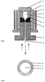
- FIG. 1 a conventional prior art extrusion process is shown for a step-index type preform. This involves applying pressure with a plunger 1 and heat with heater 3 in high pressure chamber 2 to the crystalline preform comprising preform core 4 and cladding preform 5 to force the material in the direction of the applied force and to afterwards deform it through the orifice of a die 6 to obtain a fiber 7 with the desired diameter.
- Figure 2 shows a cut cross section of fiber 7 from the method shown in Figure 1. It is observed, unfortunately, that the resulting fiber 7 shows pronounced deformations of the geometry of core 8 and clad 9 and shows intermeshing of core 8 and clad 9 materials. This rough core-cladding interface frequently causes high scattering losses in the fiber.
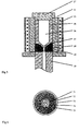
- high pressure chamber 22 includes heater 23, core preform 24, and cladding preform 25.
- plunger 29 is below the preforms and moves upwardly, i.e. against the flow.
- Cap 27 holds the preforms in place and, as plunger 29 moves die 28 upwardly, fiber 30 is extruded downwardly therefrom.
- Figure 4 shows a cross-sectional cut of fiber 30 from the process of Figure 3, wherein clad 31 and core 32 have a smooth, consistent interface with a relatively consistent clad thickness and core shape.
- the main advantage of this method is probably the fixed position of a preform in the chamber which eliminates the friction at the lateral surface of the preform and, therefore, also eliminates the release of friction energy.
- the inhomogeneous deformation of complex step-index or gradient-index preforms due to friction-caused turbulence is practically inhomogeneous.
- the intermeshing between core and cladding layers is remarkably reduced.
- Figure 5 shows a further advance according to the present invention.
- the same equipment as shown in Figure 3 is used, with like parts identically numbered.
- additional cladding material 35 can be inserted not only at the side but also below the cylindrical core preform 36, as shown as base 37.
- Figure 6 illustrates a cross-section of a preform successively deformed of its periphery consisting of a core 74 and a crystalline cladding 75, a layer of polymer lubrication 72 and a protective coating 73 of metal or polymer.
- This preform is particularly advantageous for the present inventive method.
- the enhanced quality of the core/cladding boundary in step-index fibers and the improved symmetry in gradient index fibers can also be realized by applying isotropic pressure through gaseous or liquid media.
- Figure 8 illustrates a cross section of present system which includes chamber 92, fluid inlet 91, heater 94, die 95, preform 93 and pressurized fluid 91, to produce fiber 96.
- a lubricant which could be used to reduce friction, can also serve as the liquid medium. Silicon oil or liquid flouropolymers could be used for this purpose.
- Argon or other inert gases seem particularly suitable for gas extrusion purposes.
- the core/clad preform being subjected to extrusion by a plunger moving in a direction opposite to the fiber flow or to liquid or gas extrusion may also be surrounded by an additional layer of relatively soft metal. This metal layer can then be extruded together with the core/clad (or gradient index) crystalline preform to form a fiber already protected by an external metal sheath against light, stresses or contamination.
- the above described types of essentially friction free extrusion substantially suppress lateral surface friction-one of the main causes of macrostructure defects and turbulence intermeshing at the core/cladding boundary.
- a crystal of solid solution of silver halide with a 50/50 ratio of chlorine and bromine, i.e. AgCl 0.5 : Br 0.5 was grown with a Hg ++ dopant (concentration 0.0003%) by known silver halide crystal growing methods and prepared as an extrusion billet in cylindrical form (15 mm in diameter and 40 mm long).
- the billet was extruded into a fiber with 1 mm diameter by the process as shown in Figure 3 and described above, i.e. by moving the plunger of 14 mm in diameter in the direction opposite to the fiber flow at about 200°C.
- the optical losses measured in the fiber by the cut-back method at 10.6 ⁇ m were 0.2 dB/m immediately after the extrusion and 0.5 dB/m 1 year later.
- a fiber of equal diameter was manufactured at the same temperature from a crystal of AgCl 0.5 : AgBr 0.5 solid solution by conventional extrusion in Figure 1 above. Its optical losses were measured as 1 dB/m right after the extrusion and 2.4 dB/m 1 year later. Both fibers were stored in black loose polymer tubes at controlled laboratory conditions to avoid environmental damages.
- Structure 73 was formed from a AgCl 0.5 : AgBr 0.5 core rod (diameter 15 mm), and a AgCl 0.7 : AgBr 0.3 cladding tube (15/18 mm diameter), a polyethylene coating tube (18/19 mm diameter) and a OFHC-copper ductile tube (19/20 mm diameter) with a bottom part in a form, suitable for laminar extrusion. Two successive extrusions of this preform through the raw of conical dies were realized with silicon oil as outer lubricant, and the diameters of the orifices were successively decreased from 17 mm to 15 mm.
- a final friction free extrusion using the Figure 3 method was realized to obtain 1 mm diameter fiber.
- the optical losses in the fiber were 1.5 dB/m at 10.6 ⁇ m.
- the tensile strength was remarkably high (120 MPa).
- Structure investigations of chemically etched fiber samples revealed a texture similar to that shown in Figures 7a and 7b, showing a fiber 50 with a core 51 and cladding 54. Note that large, elongated grains 52 are formed toward the center and smaller elongated grains are formed toward and in the cladding, such as grains 53.
- a step-index type fiber was produced by the method illustrated in Figure 3 from a predeformed preform (as shown in Figure 5).
- the extrusion billet (15 mm diameter and 40 mm long) consisted of a single crystalline rod of AgCl 0.24 : Br 0.76 solid solution (10 mm diameter and 38 mm long) being inserted in a hollow cylinder cladding of AgCl 0.5 : Br 0.5 solid solution (inner diameter 10 mm, outer diameter 15 mm, length 38 mm) and a disk of cladding material was placed at the bottom (diameter 15 mm and 2 mm thickness).
- the billet was hot extruded (at about 200°C) by friction free extrusion into a fiber of 0.7 mm outside diameter and 0.47 mm core diameter. Good quality of the core-cladding boundary was observed over the length of about 10 m.
Landscapes
- Chemical & Material Sciences (AREA)
- Engineering & Computer Science (AREA)
- Physics & Mathematics (AREA)
- Materials Engineering (AREA)
- Organic Chemistry (AREA)
- Crystallography & Structural Chemistry (AREA)
- General Physics & Mathematics (AREA)
- Optics & Photonics (AREA)
- Life Sciences & Earth Sciences (AREA)
- Geochemistry & Mineralogy (AREA)
- Metallurgy (AREA)
- General Life Sciences & Earth Sciences (AREA)
- General Chemical & Material Sciences (AREA)
- Chemical Kinetics & Catalysis (AREA)
- Manufacturing & Machinery (AREA)
- Health & Medical Sciences (AREA)
- Toxicology (AREA)
- Inorganic Chemistry (AREA)
- Glass Compositions (AREA)
- Extrusion Moulding Of Plastics Or The Like (AREA)
Description
- The present invention relates to a method of making silver halide crystalline fibers capable of transmitting infrared light and to the fiber product made by the process. Infrared fibers are of technical interest for the transmission fo low power radiation signals from the environment, such as heat radiation to infrared tectors. They are of further interest in remote infrared spectroscopy and in the transmission of laser energy from CO2 and CO lasers in particular.
- Silver halide fibers consisting of silver chloride (AgCl), silver bromide (AgBr), and their solid solutions (AgClxBr1-x) show promising properties for the transmission of middle infrared radiation. The fibers can either be bare core fibers, with gas functioning as the lower refractive index, total reflecting medium or polymer coated fibers or core/clad fibers where the cladding contains more AgCl for total internal reflection. These are described in United States Patent Numbers 4,253,731; 4,381,141; 4,504,298 and 4,552,434 and considerable improvements have been reported over time.
- Nevertheless, there are some drawbacks in present silver halide crystalline fibers. One basic disadvantage of both bare core and step-index core/clad silver halide fibers is their tendency to deteriorate optically and mechanically probably due to recrystallization of the grain structure, phase separation and silver colloids formation as well as absorption and diffusion of extrinsic impurities.
- Transmission and elasticity have been observed to decrease remarkably when present state-of-the-art fibers are bent repeatedly. This is a result of defect formation linked to the plastic deformation of the granular structure of the fibers. Present core/clad fibers frequently show intermeshing between the core and the clad material during their extrusion and, as a result, bad transmission. This defect arises due to inhomogeneous deformation during the conventional extrusion process. Further, fibers produced by alternative manufacturing methods such as multiple step-deformation by drawing the fiber through a row of dies as in, for example, United States Patents 4,381,141; 4,504,298 and 4,552,434, show defects such as microvoids and microcracks. It is assumed that these scattering defects result from the stretching stress applied in these manufacturing methods. The core/cladding boundary also shows defects if the process of successive rolling by grooved rolls is applied as suggested in some of the above prior art, probably due to the non-symmetric deformation mechanism. Additionally, trace contamination by lubricants or other extrinsic impurities is generally observed when multiple deformation methods are employed and these methods are more complicated and less productive than the conventional extrusion process. JP 58 043 404 A discloses a process with the features of the preamble of claims 1-3. From JP 57 208 506 A it is known to produce a crystalline halide optical fiber having larger grain size at the core center part and with crystal grain size decreasing sucessively to the external circumference. From JP 02 302 705 A it is known to place assistant crystal under a preform crystal in an extrusion container to reduce the impact on pressing the preform.
- The present invention is directed to processes for the extrusion of optical silver halide fibers according to claims 1-3 and to optical silver halide fibers produced by any one of said processes according to claim 4. The resulting fiber has a more even core/clad interface with decrease in grain size to fiber surface and texture elongated along the fiber axis. This structure together with strengthening and stabilizing dopants, added to fiber material, gives decreased and stabilized optical losses and a higher elasticity of fibers.
- The present invention is more fully understood when the instant specification is taken in conjunction with the drawings which are appended hereto, wherein:
- Figure 1 shows a side cut view of a conventional extrusion processing equipment with the process in progress;
- Figure 2 shows the resulting cross-section for a step-index type infrared crystalline fiber using the method of the prior art shown in Figure 1;
- Figure 3 shows a cut side view of equipment for the extrusion in accordance with a conventional process with the process in progress;
- Figure 4 shows a related cross-section of step-index fiber being produced by the process in Figure 3;
- Figure 5 shows a preferred starting preform geometry for the laminar flow of extrusion in the present invention process;
- Figure 6 shows a cross-section of a preform of the present invention with more details and being successively deformed at is periphery, consisting of a crystalline core and a crystalline cladding layer, a layer of polymer lubricant and a protective polymer or metal coating;
- Figures 7a and 7b show a cross sectional cut of the fiber texture after extrusion of a predeformed core/clad preform of the present invention, and a side cut view of that fiber; and,
- Figure 8 shows a side cut view of a present invention method arrangement for hydraulic extrusion in progress.
-
- One object of the present invention is to provide a material composition and process for producing an infrared light transmitting crystalline fiber having good and stable elasticity and a stable, low level of optical losses.
- The production method should guarantee a grain structure reacting favorable to multiple bending of the fibers. At the same time, the method should avoid the current shortcomings of core/clad intermeshing and microcracks/microvoids as well as surface contamination.
- Preferably, the present invention achieves these objectives and overcomes the deficiencies of conventional techniques by stabilizing the composition of the main silver halide components by suitable dopants, by a pre extrusion treatment of the preform to form a strengthened profile of texture elongated along the preform axis, and by maintaining laminar flow conditions during the extrusion process by applying the extrusion pressure to the prepared preform in a direction opposite to the fiber flow.
- We have found that photodegradation can be remarkably reduced by partially replacing halide anions by iodine and/or partially replacing silver cations by any alkali metals or by double valent cations. It is assumed that the homogenous distribution of the above listed elements in the fiber material creates additional barriers for the sliding and recrystallization effect in polycrystalline fibers and restricts the silver ion diffusion. This self-diffusion of interstitial silver ions determines the formation of silver colloids, that absorb the transmitted radiation.
- Metal compounds suitable for doping are MY, type compound wherein M is a metal selected from Li, Na, K, Rb, Cs, or they are MeY2 type where Me is selected from Mg, Ca, Sr, Ba, Cd, Pb or Hg, and Y is Cl, Br or I.
- The expected effect of AgI crystallographic structure transition during the cooling of this crystal after its growth from the melt was surprisingly suppressed by limiting the content of AgI to less then 5% of the AgCl-AgBr matrix.
- It was also determined that the concentration of double valent cations (Hg, Cd, Pb, etc.) needs to be restricted to less than 0.001% probably due to the substantial physical difference between them and the host cations of the lattice matrix.
- The positive effect of the doping of the silver halide crystals on the transmission stability of the fibers can be observed with any chosen fiber structure (for examples, core only with gas as lower index surrounding, core with polymer cladding, core/clad fiber with silver halide core and lower refractive index silver halide compositions, cladding or graded index silver halide fiber).
- It was observed that the grain structure in the finished fiber can be influenced by pretreating the preform used for the fiber extrusion. If the preform is carefully deformed by exerting pressure to its lateral surface by preextrusion or by other methods with a low extent of deformation (<2) a texture with elongated grains is achieved. The texture is finer at the outside of the deformed preform while larger crystalline grains are prevailing at the inner core area. We have observed that fibers extruded from above described preforms exhibit similar texture and show improved transmission and stability. It is assumed that the fiber with a texture of superfine (0.01 to 0.2 µm) ellipsoidally shaped crystalline grains, elongated along the fiber axis and decreased in size in the peripherical fiber layers, deforms more elastically and with less defect formation when multiple bending of the fiber occurs, than a fiber with conventional, round shaped grain structure. Furtheron, the essentially longitudinal directed radiation rays pass over fewer grain boundaries and defects, which may further explain the enhanced transmission properties.
- Referring now to Figure 1, a conventional prior art extrusion process is shown for a step-index type preform. This involves applying pressure with a
plunger 1 and heat withheater 3 inhigh pressure chamber 2 to the crystalline preform comprising preform core 4 and claddingpreform 5 to force the material in the direction of the applied force and to afterwards deform it through the orifice of a die 6 to obtain afiber 7 with the desired diameter. - Figure 2 shows a cut cross section of
fiber 7 from the method shown in Figure 1. It is observed, unfortunately, that the resultingfiber 7 shows pronounced deformations of the geometry of core 8 andclad 9 and shows intermeshing of core 8 and clad 9 materials. This rough core-cladding interface frequently causes high scattering losses in the fiber. - We attributed this shortcoming of the extrusion process to the friction of the material on the cylindrical chamber surface and to the related turbulences in the material flow. We have found, however, that by inversing the plunger movement (movement of the plunger in a direction opposite to the fiber movement) the problem can be essentially overcome and the fiber geometry remarkably improved.
- In Figure 3,
high pressure chamber 22, includesheater 23,core preform 24, andcladding preform 25. However, here,plunger 29 is below the preforms and moves upwardly, i.e. against the flow.Cap 27 holds the preforms in place and, asplunger 29 moves die 28 upwardly,fiber 30 is extruded downwardly therefrom. - Figure 4 shows a cross-sectional cut of
fiber 30 from the process of Figure 3, wherein clad 31 andcore 32 have a smooth, consistent interface with a relatively consistent clad thickness and core shape. - The main advantage of this method is probably the fixed position of a preform in the chamber which eliminates the friction at the lateral surface of the preform and, therefore, also eliminates the release of friction energy. The inhomogeneous deformation of complex step-index or gradient-index preforms due to friction-caused turbulence is practically inhomogeneous. The intermeshing between core and cladding layers is remarkably reduced.
- But even with the above described extrusion process, some residual irregularities for the starting stage of the extrusion may be observed. Figure 5 shows a further advance according to the present invention. Here, the same equipment as shown in Figure 3 is used, with like parts identically numbered. However, to reach the laminar flow geometry faster,
additional cladding material 35 can be inserted not only at the side but also below thecylindrical core preform 36, as shown asbase 37. - Further, by keeping the plunger diameter marginally smaller than the preform diameter, surface contamination from the chamber surface or preform surface defects are effectively excluded from entering the finished fiber. In this way, our claimed extrusion process for silver halide fiber production shows additional benefits also for core-only or plastic clad/core fiber manufacturing.
- Figure 6 illustrates a cross-section of a preform successively deformed of its periphery consisting of a
core 74 and acrystalline cladding 75, a layer ofpolymer lubrication 72 and aprotective coating 73 of metal or polymer. This preform is particularly advantageous for the present inventive method. The enhanced quality of the core/cladding boundary in step-index fibers and the improved symmetry in gradient index fibers can also be realized by applying isotropic pressure through gaseous or liquid media. Thus, Figure 8 illustrates a cross section of present system which includeschamber 92,fluid inlet 91,heater 94, die 95,preform 93 andpressurized fluid 91, to producefiber 96. A lubricant, which could be used to reduce friction, can also serve as the liquid medium. Silicon oil or liquid flouropolymers could be used for this purpose. Argon or other inert gases seem particularly suitable for gas extrusion purposes. - The core/clad preform being subjected to extrusion by a plunger moving in a direction opposite to the fiber flow or to liquid or gas extrusion may also be surrounded by an additional layer of relatively soft metal. This metal layer can then be extruded together with the core/clad (or gradient index) crystalline preform to form a fiber already protected by an external metal sheath against light, stresses or contamination.
- The above described types of essentially friction free extrusion substantially suppress lateral surface friction-one of the main causes of macrostructure defects and turbulence intermeshing at the core/cladding boundary.
- The processes described above are further illustrated by the following examples.
- A crystal of solid solution of silver halide with a 50/50 ratio of chlorine and bromine, i.e. AgCl0.5 : Br0.5 was grown with a Hg++ dopant (concentration 0.0003%) by known silver halide crystal growing methods and prepared as an extrusion billet in cylindrical form (15 mm in diameter and 40 mm long). The billet was extruded into a fiber with 1 mm diameter by the process as shown in Figure 3 and described above, i.e. by moving the plunger of 14 mm in diameter in the direction opposite to the fiber flow at about 200°C. The optical losses measured in the fiber by the cut-back method at 10.6 µm were 0.2 dB/m immediately after the extrusion and 0.5 dB/
m 1 year later. For comparative purposes a fiber of equal diameter was manufactured at the same temperature from a crystal of AgCl0.5 : AgBr0.5 solid solution by conventional extrusion in Figure 1 above. Its optical losses were measured as 1 dB/m right after the extrusion and 2.4 dB/m 1 year later. Both fibers were stored in black loose polymer tubes at controlled laboratory conditions to avoid environmental damages. - The preform of a structure such as is shown in cross-section in Figure 6.
Structure 73 was formed from a AgCl0.5 : AgBr0.5 core rod (diameter 15 mm), and a AgCl0.7 : AgBr0.3 cladding tube (15/18 mm diameter), a polyethylene coating tube (18/19 mm diameter) and a OFHC-copper ductile tube (19/20 mm diameter) with a bottom part in a form, suitable for laminar extrusion. Two successive extrusions of this preform through the raw of conical dies were realized with silicon oil as outer lubricant, and the diameters of the orifices were successively decreased from 17 mm to 15 mm. A final friction free extrusion using the Figure 3 method was realized to obtain 1 mm diameter fiber. The optical losses in the fiber were 1.5 dB/m at 10.6 µm. The tensile strength was remarkably high (120 MPa). Structure investigations of chemically etched fiber samples revealed a texture similar to that shown in Figures 7a and 7b, showing afiber 50 with acore 51 and cladding 54. Note that large,elongated grains 52 are formed toward the center and smaller elongated grains are formed toward and in the cladding, such asgrains 53. - It was observed that the fiber could withstand significantly more and several bend cycles than fibers produced directly from non-predeformed crystals described above.
- A step-index type fiber was produced by the method illustrated in Figure 3 from a predeformed preform (as shown in Figure 5). The extrusion billet (15 mm diameter and 40 mm long) consisted of a single crystalline rod of AgCl0.24 : Br0.76 solid solution (10 mm diameter and 38 mm long) being inserted in a hollow cylinder cladding of AgCl0.5 : Br0.5 solid solution (
inner diameter 10 mm, outer diameter 15 mm, length 38 mm) and a disk of cladding material was placed at the bottom (diameter 15 mm and 2 mm thickness). The billet was hot extruded (at about 200°C) by friction free extrusion into a fiber of 0.7 mm outside diameter and 0.47 mm core diameter. Good quality of the core-cladding boundary was observed over the length of about 10 m. - Without the insertion of the extra cladding material at the bottom (near the die) much smaller yield was observed due to several meters of start up loss.
- Obviously, numerous modifications and variations of the present invention are possible in light of the above teachings. It is, therefore, understood that within the scope of the appended claims, the invention may be practiced otherwise than as specifically described herein.
Claims (7)
- Process for extrusion of optical silver halide fiber, comprising the steps of: reducing turbulence and friction during extrusion by moving material through an extrusion die by utilizing force to extrude, which force includes pressure from directions other than the direction of flow of the resulting fiber, characterized by compressing the preform on at least its top and side with inert gas or liquid while forcing the fiber material flow through said die.
- Process for extrusion of optical silver halide fiber, comprising the steps of: reducing turbulence and friction during extrusion by moving material through an extrusion die by utilizing force to extrude, which force includes pressure from directions other than the direction of flow of the resulting fiber, characterized in that the preform has a core and cladding exhibiting a lower refractive index than the core and additional clad material is inserted into an extrusion chamber on at least the bottom of the preform rod.
- Process for extrusion of optical silver halide fiber, comprising the steps of: reducing turbulence and friction during extrusion by moving material through an extrusion die by utilizing force to extrude, which force includes pressure from directions other than the direction of flow of the resulting fiber, characterized by including predeforming the preform by compression at its periphery to form a grain texture oriented parallel to the preform and extrusion axes with grain size decreasing from the center of the preform towards its periphery.
- Optical silver halide fiber produced by the process of any of the previous claims, wherein the fiber has a polycrystalline, essentially void- and microcrack-free texture and the grain size decreases from the center of the core towards the periphery and the grains are elongated and oriented with their longitudinal direction parallel to the fiber axis.
- Optical fiber according to claim 4, wherein said fiber is unclad.
- Optical fiber according to claim 4 or 5, wherein said fiber has a core coated with polymer having a lower refractive index than said core.
- Optical fiber according to claim 4, wherein said fiber is clad with a lower refractive index silver halide cladding material of the formula AgClzBr1-z, wherein Z is from 0 to 1.0.
Priority Applications (7)
| Application Number | Priority Date | Filing Date | Title |
|---|---|---|---|
| US07/980,289 US5309543A (en) | 1992-11-23 | 1992-11-23 | Method of making infrared crystalline fiber and product |
| US08/013,648 US5342022A (en) | 1992-11-23 | 1993-02-04 | Method of making infrared crystalline fiber |
| ES93118812T ES2159514T3 (en) | 1993-11-23 | 1993-11-23 | METHOD FOR PREPARING CRYSTAL FIBERS FOR INFRARED AND PRODUCT. |
| DE69330522T DE69330522T2 (en) | 1993-11-23 | 1993-11-23 | Process for producing a crystalline infrared fiber and the product thus obtained |
| EP99124876A EP1006089B1 (en) | 1993-11-23 | 1993-11-23 | Infrared crystalline optical fibre |
| DE9321581U DE9321581U1 (en) | 1993-11-23 | 1993-11-23 | Silver halide crystalline fibers |
| EP93118812A EP0655423B1 (en) | 1992-11-23 | 1993-11-23 | Method of making infrared crystalline fiber and product |
Applications Claiming Priority (2)
| Application Number | Priority Date | Filing Date | Title |
|---|---|---|---|
| US07/980,289 US5309543A (en) | 1992-11-23 | 1992-11-23 | Method of making infrared crystalline fiber and product |
| EP93118812A EP0655423B1 (en) | 1992-11-23 | 1993-11-23 | Method of making infrared crystalline fiber and product |
Related Child Applications (1)
| Application Number | Title | Priority Date | Filing Date |
|---|---|---|---|
| EP99124876A Division EP1006089B1 (en) | 1993-11-23 | 1993-11-23 | Infrared crystalline optical fibre |
Publications (2)
| Publication Number | Publication Date |
|---|---|
| EP0655423A1 EP0655423A1 (en) | 1995-05-31 |
| EP0655423B1 true EP0655423B1 (en) | 2001-08-01 |
Family
ID=26133523
Family Applications (1)
| Application Number | Title | Priority Date | Filing Date |
|---|---|---|---|
| EP93118812A Expired - Lifetime EP0655423B1 (en) | 1992-11-23 | 1993-11-23 | Method of making infrared crystalline fiber and product |
Country Status (2)
| Country | Link |
|---|---|
| US (2) | US5309543A (en) |
| EP (1) | EP0655423B1 (en) |
Families Citing this family (19)
| Publication number | Priority date | Publication date | Assignee | Title |
|---|---|---|---|---|
| US5796903A (en) * | 1992-07-06 | 1998-08-18 | Infrared Fiber Systems, Inc. | Heavy metal-oxide glass optical fibers for use in laser medical surgery and process of making |
| DE19841217B4 (en) * | 1997-10-27 | 2005-06-16 | Applied Photonics Worldwide, Inc., Reno | Apparatus and method for the spectroscopic analysis of human or animal tissue or body fluids |
| ATE517065T1 (en) * | 1998-11-24 | 2011-08-15 | Corning Inc | METHOD OF APPLYING A PROTECTIVE COATING TO OBJECTS CONTAINING SILICA |
| US6767579B1 (en) | 1998-11-24 | 2004-07-27 | Corning Incorporated | Methods for protecting silica-containing article in optical fiber manufacturing |
| NO20023605D0 (en) * | 2002-07-29 | 2002-07-29 | Sumit Roy | Method and apparatus for interconnecting two tubular members |
| US7504154B2 (en) * | 2005-03-23 | 2009-03-17 | Lockheed Martin Corporation | Moisture barrier coatings for infrared salt optics |
| US7312422B2 (en) * | 2006-03-17 | 2007-12-25 | Momentive Performance Materials Inc. | Semiconductor batch heating assembly |
| US7901509B2 (en) * | 2006-09-19 | 2011-03-08 | Momentive Performance Materials Inc. | Heating apparatus with enhanced thermal uniformity and method for making thereof |
| CN104204315B (en) | 2012-01-20 | 2019-03-15 | 自由形态纤维有限公司 | High-strength ceramic fiber and its manufacturing method |
| US9938393B2 (en) * | 2015-01-23 | 2018-04-10 | Free Form Fibers, Llc | Radially graded fully dense inorganic filaments for enhanced strength and creep resistance |
| US12133465B2 (en) | 2016-05-11 | 2024-10-29 | Free Form Fibers, Llc | Multilayer functional fiber and method of making |
| US10676391B2 (en) | 2017-06-26 | 2020-06-09 | Free Form Fibers, Llc | High temperature glass-ceramic matrix with embedded reinforcement fibers |
| WO2019005911A1 (en) | 2017-06-27 | 2019-01-03 | Free Form Fibers, Llc | Functional high-performance fiber structure |
| US12006605B2 (en) | 2019-09-25 | 2024-06-11 | Free Form Fibers, Llc | Non-woven micro-trellis fabrics and composite or hybrid-composite materials reinforced therewith |
| US12415763B2 (en) | 2020-01-27 | 2025-09-16 | Free Form Fibers, Llc | High purity ingot for wafer production |
| US12312682B2 (en) | 2020-01-27 | 2025-05-27 | Free Form Fibers, Llc | High purity fiber feedstock for loose grain production |
| US11761085B2 (en) | 2020-08-31 | 2023-09-19 | Free Form Fibers, Llc | Composite tape with LCVD-formed additive material in constituent layer(s) |
| EP4359363A4 (en) | 2021-06-21 | 2025-05-07 | Free Form Fibers, LLC | Fiber structures with embedded sensors |
| EP4363630A4 (en) | 2021-06-29 | 2025-07-09 | Free Form Fibers Llc | Wire-embedded chemical vapor deposition (EWCVD) |
Family Cites Families (15)
| Publication number | Priority date | Publication date | Assignee | Title |
|---|---|---|---|---|
| US2659132A (en) * | 1950-08-16 | 1953-11-17 | Dow Chemical Co | Composite alloy |
| US3797910A (en) * | 1971-09-14 | 1974-03-19 | Corning Glass Works | Fiber optic device having some fibers clad with absorbing glasses |
| US4171400A (en) * | 1976-01-15 | 1979-10-16 | The Harshaw Chemical Company | Shaped press-forged normally frangible inorganic crystals |
| US4253731A (en) * | 1979-04-09 | 1981-03-03 | Honeywell Inc. | Infrared fiber of AgCl clad AgBr and method of fabrication |
| JPS585406B2 (en) * | 1980-01-22 | 1983-01-31 | 工業技術院長 | Infrared optical fiber and its manufacturing method |
| CA1170805A (en) * | 1981-01-23 | 1984-07-17 | Minoru Yokota | Process for producing infrared light transmitting optical fiber |
| JPS57208506A (en) * | 1981-06-18 | 1982-12-21 | Matsushita Electric Ind Co Ltd | Optical fiber and its manufacture |
| JPS5843404A (en) * | 1981-09-09 | 1983-03-14 | Sumitomo Electric Ind Ltd | Method and device for producing fiber for infrared light |
| US4552434A (en) * | 1982-03-16 | 1985-11-12 | Sumitomo Electric Industries, Ltd. | Crystalline infrared optical fiber with a small gap and a process for the production of same |
| JPS6122304A (en) * | 1984-07-11 | 1986-01-30 | Matsushita Electric Ind Co Ltd | Method for manufacturing polycrystalline infrared optical fiber |
| IL81690A0 (en) * | 1986-03-15 | 1987-09-16 | Sumitomo Electric Industries | Crystalline optical fiber and its manufacture |
| US4955689A (en) * | 1987-12-17 | 1990-09-11 | Fuller Research Corporation | IR transmitting optical fiber |
| JPH0210302A (en) * | 1988-06-29 | 1990-01-16 | Matsushita Electric Ind Co Ltd | Single crystal infrared fiber manufacturing method |
| JPH02302705A (en) * | 1989-05-18 | 1990-12-14 | Matsushita Electric Ind Co Ltd | Production of optical fiber for infrared ray |
| JPH03288804A (en) * | 1990-04-05 | 1991-12-19 | Matsushita Electric Ind Co Ltd | Infrared optical fiber and its manufacturing method |
-
1992
- 1992-11-23 US US07/980,289 patent/US5309543A/en not_active Expired - Lifetime
-
1993
- 1993-02-04 US US08/013,648 patent/US5342022A/en not_active Expired - Fee Related
- 1993-11-23 EP EP93118812A patent/EP0655423B1/en not_active Expired - Lifetime
Also Published As
| Publication number | Publication date |
|---|---|
| US5342022A (en) | 1994-08-30 |
| EP0655423A1 (en) | 1995-05-31 |
| US5309543A (en) | 1994-05-03 |
Similar Documents
| Publication | Publication Date | Title |
|---|---|---|
| US5342022A (en) | Method of making infrared crystalline fiber | |
| US4504298A (en) | Process for producing infrared light transmitting optical fiber | |
| DE69319999T2 (en) | Process for the production of a large quartz glass tube, as well as a preform and an optical fiber | |
| US4253731A (en) | Infrared fiber of AgCl clad AgBr and method of fabrication | |
| CA1246913A (en) | Low loss cladded optical fibers from halides and process for making same | |
| DE60032363T2 (en) | OPTICAL FIBER WITH LOW POLARIZATION MODE DISPERSION AND CUSHIONING AND ITS MANUFACTURING METHOD | |
| DE2300013B2 (en) | Process for making optical waveguides | |
| DE2349906B2 (en) | Fiber optic transmission line | |
| EP3766840B1 (en) | Method for producing a hollow core fibre and for producing a preform for a hollow core fibre | |
| CA1283568C (en) | Crystalline optical fiber and its method of manufacture | |
| DE69031607T2 (en) | Fiber optic bundle for image transmission and its manufacturing process | |
| CA1236718A (en) | Crystalline fiber and a process for the production of the same | |
| EP1006089B1 (en) | Infrared crystalline optical fibre | |
| DE2827303C2 (en) | Process for the production of a glass object and its application | |
| US10118853B2 (en) | Systems and methods for producing robust chalcogenide optical fibers | |
| EP2545009B1 (en) | Process and tubular preform for manufacturing an optical fibre | |
| EP1251107A1 (en) | Controlled collapse of depressed index optical fiber preforms | |
| DE69408021T2 (en) | Process for increasing the refractive index of glass | |
| EP0127227B1 (en) | Method of manufacturing optical wave guides | |
| DE69334047T2 (en) | Crystalline infrared optical fiber | |
| DE9321581U1 (en) | Silver halide crystalline fibers | |
| RU2780763C1 (en) | Method for producing an ir shell polycrystalline fibre light guide | |
| EP0541738A1 (en) | METHOD FOR PRODUCING A PREFORM. | |
| JPS62102203A (en) | Crystal fiber and its production | |
| US5666454A (en) | Preform for optical fiber and method of producing optical fiber |
Legal Events
| Date | Code | Title | Description |
|---|---|---|---|
| PUAI | Public reference made under article 153(3) epc to a published international application that has entered the european phase |
Free format text: ORIGINAL CODE: 0009012 |
|
| AK | Designated contracting states |
Kind code of ref document: A1 Designated state(s): DE ES FR GB IT |
|
| 17P | Request for examination filed |
Effective date: 19950721 |
|
| 17Q | First examination report despatched |
Effective date: 19990224 |
|
| GRAG | Despatch of communication of intention to grant |
Free format text: ORIGINAL CODE: EPIDOS AGRA |
|
| GRAG | Despatch of communication of intention to grant |
Free format text: ORIGINAL CODE: EPIDOS AGRA |
|
| GRAH | Despatch of communication of intention to grant a patent |
Free format text: ORIGINAL CODE: EPIDOS IGRA |
|
| GRAH | Despatch of communication of intention to grant a patent |
Free format text: ORIGINAL CODE: EPIDOS IGRA |
|
| GRAA | (expected) grant |
Free format text: ORIGINAL CODE: 0009210 |
|
| AK | Designated contracting states |
Kind code of ref document: B1 Designated state(s): DE ES FR GB IT |
|
| ITF | It: translation for a ep patent filed | ||
| REF | Corresponds to: |
Ref document number: 69330522 Country of ref document: DE Date of ref document: 20010906 |
|
| REG | Reference to a national code |
Ref country code: ES Ref legal event code: FG2A Ref document number: 2159514 Country of ref document: ES Kind code of ref document: T3 |
|
| ET | Fr: translation filed | ||
| REG | Reference to a national code |
Ref country code: GB Ref legal event code: IF02 |
|
| PLBE | No opposition filed within time limit |
Free format text: ORIGINAL CODE: 0009261 |
|
| STAA | Information on the status of an ep patent application or granted ep patent |
Free format text: STATUS: NO OPPOSITION FILED WITHIN TIME LIMIT |
|
| 26N | No opposition filed | ||
| PGFP | Annual fee paid to national office [announced via postgrant information from national office to epo] |
Ref country code: FR Payment date: 20031118 Year of fee payment: 11 |
|
| PGFP | Annual fee paid to national office [announced via postgrant information from national office to epo] |
Ref country code: ES Payment date: 20031121 Year of fee payment: 11 |
|
| PG25 | Lapsed in a contracting state [announced via postgrant information from national office to epo] |
Ref country code: ES Free format text: LAPSE BECAUSE OF NON-PAYMENT OF DUE FEES Effective date: 20041124 |
|
| PG25 | Lapsed in a contracting state [announced via postgrant information from national office to epo] |
Ref country code: FR Free format text: LAPSE BECAUSE OF NON-PAYMENT OF DUE FEES Effective date: 20050729 |
|
| REG | Reference to a national code |
Ref country code: FR Ref legal event code: ST |
|
| PG25 | Lapsed in a contracting state [announced via postgrant information from national office to epo] |
Ref country code: IT Free format text: LAPSE BECAUSE OF NON-PAYMENT OF DUE FEES;WARNING: LAPSES OF ITALIAN PATENTS WITH EFFECTIVE DATE BEFORE 2007 MAY HAVE OCCURRED AT ANY TIME BEFORE 2007. THE CORRECT EFFECTIVE DATE MAY BE DIFFERENT FROM THE ONE RECORDED. Effective date: 20051123 |
|
| REG | Reference to a national code |
Ref country code: ES Ref legal event code: FD2A Effective date: 20041124 |
|
| PGFP | Annual fee paid to national office [announced via postgrant information from national office to epo] |
Ref country code: GB Payment date: 20121122 Year of fee payment: 20 |
|
| PGFP | Annual fee paid to national office [announced via postgrant information from national office to epo] |
Ref country code: DE Payment date: 20130122 Year of fee payment: 20 |
|
| REG | Reference to a national code |
Ref country code: DE Ref legal event code: R071 Ref document number: 69330522 Country of ref document: DE |
|
| REG | Reference to a national code |
Ref country code: DE Ref legal event code: R071 Ref document number: 69330522 Country of ref document: DE |
|
| REG | Reference to a national code |
Ref country code: GB Ref legal event code: PE20 Expiry date: 20131122 |
|
| PG25 | Lapsed in a contracting state [announced via postgrant information from national office to epo] |
Ref country code: DE Free format text: LAPSE BECAUSE OF EXPIRATION OF PROTECTION Effective date: 20131126 Ref country code: GB Free format text: LAPSE BECAUSE OF EXPIRATION OF PROTECTION Effective date: 20131122 |