EP0655123B1 - Electronic level displaying inclination with regard to instrument length - Google Patents
Electronic level displaying inclination with regard to instrument length Download PDFInfo
- Publication number
- EP0655123B1 EP0655123B1 EP93919925A EP93919925A EP0655123B1 EP 0655123 B1 EP0655123 B1 EP 0655123B1 EP 93919925 A EP93919925 A EP 93919925A EP 93919925 A EP93919925 A EP 93919925A EP 0655123 B1 EP0655123 B1 EP 0655123B1
- Authority
- EP
- European Patent Office
- Prior art keywords
- inclination
- level
- display
- null
- scale
- Prior art date
- Legal status (The legal status is an assumption and is not a legal conclusion. Google has not performed a legal analysis and makes no representation as to the accuracy of the status listed.)
- Expired - Lifetime
Links
- 230000000007 visual effect Effects 0.000 claims abstract description 13
- 238000000034 method Methods 0.000 claims description 12
- 238000005259 measurement Methods 0.000 claims description 5
- 230000005284 excitation Effects 0.000 claims description 4
- 238000012935 Averaging Methods 0.000 claims description 3
- 238000006243 chemical reaction Methods 0.000 claims 1
- UDQDXYKYBHKBTI-IZDIIYJESA-N 2-[4-[4-[bis(2-chloroethyl)amino]phenyl]butanoyloxy]ethyl (2e,4e,6e,8e,10e,12e)-docosa-2,4,6,8,10,12-hexaenoate Chemical compound CCCCCCCCC\C=C\C=C\C=C\C=C\C=C\C=C\C(=O)OCCOC(=O)CCCC1=CC=C(N(CCCl)CCCl)C=C1 UDQDXYKYBHKBTI-IZDIIYJESA-N 0.000 description 18
- 230000008859 change Effects 0.000 description 6
- 238000010586 diagram Methods 0.000 description 3
- 230000006870 function Effects 0.000 description 3
- 230000008569 process Effects 0.000 description 3
- 239000012530 fluid Substances 0.000 description 2
- 230000035945 sensitivity Effects 0.000 description 2
- 230000009471 action Effects 0.000 description 1
- 230000004913 activation Effects 0.000 description 1
- 230000004397 blinking Effects 0.000 description 1
- 238000010276 construction Methods 0.000 description 1
- 238000001514 detection method Methods 0.000 description 1
- 238000006073 displacement reaction Methods 0.000 description 1
- 230000005484 gravity Effects 0.000 description 1
- 238000003825 pressing Methods 0.000 description 1
- 239000007787 solid Substances 0.000 description 1
- 230000007704 transition Effects 0.000 description 1
- 238000005303 weighing Methods 0.000 description 1
- 238000009736 wetting Methods 0.000 description 1
- 229910052845 zircon Inorganic materials 0.000 description 1
- GFQYVLUOOAAOGM-UHFFFAOYSA-N zirconium(iv) silicate Chemical compound [Zr+4].[O-][Si]([O-])([O-])[O-] GFQYVLUOOAAOGM-UHFFFAOYSA-N 0.000 description 1
Images




Classifications
-
- G—PHYSICS
- G01—MEASURING; TESTING
- G01C—MEASURING DISTANCES, LEVELS OR BEARINGS; SURVEYING; NAVIGATION; GYROSCOPIC INSTRUMENTS; PHOTOGRAMMETRY OR VIDEOGRAMMETRY
- G01C9/00—Measuring inclination, e.g. by clinometers, by levels
- G01C9/18—Measuring inclination, e.g. by clinometers, by levels by using liquids
- G01C9/20—Measuring inclination, e.g. by clinometers, by levels by using liquids the indication being based on the inclination of the surface of a liquid relative to its container
-
- G—PHYSICS
- G01—MEASURING; TESTING
- G01C—MEASURING DISTANCES, LEVELS OR BEARINGS; SURVEYING; NAVIGATION; GYROSCOPIC INSTRUMENTS; PHOTOGRAMMETRY OR VIDEOGRAMMETRY
- G01C9/00—Measuring inclination, e.g. by clinometers, by levels
- G01C9/02—Details
- G01C9/06—Electric or photoelectric indication or reading means
Definitions
- This invention relates to an electronic level and specifically to the visual display and calibration of the level.
- the rise/run mode 122 is determined by first using the determine angle routine of block 146 and the display routine of block 148.
- the display function is calculated at twelve times the tangent of the angle determined by block 146. This gives the rise to run value of inches per foot.
- an inclination sensor device comprising: a sensor for determining an inclination of the device relative to a null inclination; and a visual display for displaying the determined inclination, the visual display comprising a plurality of illuminated parallel and adjacent line segments, each line segment representing a predetermine increment of inclination expressed as a linear deviation per linear length, a particular number of line segments being displayed for each said determined inclination.
- the invention also provides a method of indicating angular deviation of a level from a particular inclination, comprising: providing on the level a scale display having a plurality of parallel and adjacent line segments; sensing an amount of the angular deviation of the level; illuminating one or more of the line segments to indicate each amount of angular deviation of the level, each illuminated line segment indicating an incremental deviation of a particular linear distance per length.
- an electronic level that has a visual display that displays rise over run (deviation from a null) in terms of deviation from the null (level or plumb) in inches per the actual length of the level instrument (such as two or four feet).
- 1 inch 25.4 mm
- 1 foot 304,8 mm.
- building tradesmen typically prefer either variable user offsets for transferring of arbitrary angles, or a series of fixed offsets such as 1 ⁇ 2 inch, 1 inch or 2 inches per linear two feet or 1 or 2 or 4 inches per linear four feet, which is readily converted to a deviation from a null (offset) per standard dimensions such as a ceiling height, door height, etc.
- the visual display includes a number of parallel line segments resembling a typical ruler scale.
- a null level or plumb or at some other preselected inclination
- only the central line segment is illuminated.
- one or more of the line segments are illuminated starting from the centre line segment.
- the more line segments that are illuminated starting from the centre line segment the greater the amount of inclination indicated.
- Each line segment in one embodiment indicates 1/64th inch of additional inclination per horizontal foot.
- the line segments on either side of the central line segment thus provide an indication of inclination in either direction, i.e. that the left end or right end of the device is inclined.
- numerals are provided associated with the scale to show the amount of inclination per arbitrary length (such as two feet or four feet) related to the instrument length. Also included is a slope indicator and a numerical indicator for indicating the fixed offset mode. In fixed offset mode the null indication is provided not at level or plumb relative to the plane of gravity, but instead at some fixed angle thereto. Typically this would be for instance 1/2 or 1 or 2 inches per two feet or 1 or 2 or 4 inches per four feet which are measurements typically used in construction or readily converted thereto.
- Butler et al. describes a calibration routine wherein electronically measured results are averaged in each of two 180° opposed positions, with the average of these two readings used as a calibrated reference by the level's microcomputer software routines. This technique is adequate when the level is calibrated and also used at a given temperature. If, however, the single sensor element of Butler et al. has any temperature sensitivity, this averaged result may no longer be valid or require temperature compensation.
- An improved calibration technique disclosed herein utilizes negative feed back with differential sensor electrodes to the sensor itself to null out any system mechanical and/or electrical offset, by feeding back to the sensor a signal which nulls out all errors. Because the sensor utilizes two differential electrodes for any given position, once the error has been nulled out by the negative feedback, any temperature sensitivity of the sensor will affect both electrodes equally and thus the calibrated position of the level will not drift.
- FIGS 1A, 1B, 1C show level displays in accordance with the invention.
- FIG. 2 shows a block diagram of the electronic circuitry in accordance with the invention.
- Figures 3A and 3B show detail of Figure 2.
- Figure 4A shows octant decode timing
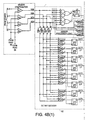
- Figure 4B shows sensor processing and octant decoding gate level logic circuitry.
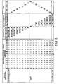
- Figure 5 shows sensor orientation and data results graphically.
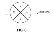
- FIG. 6 shows wetting of the capacitive sensors in accordance with the invention.
- Figure 7 shows extraneous sensor electrode nulls.
- the level disclosed herein includes improvements over the level disclosed in commonly owned U.S. Patent 5,083,383 issued January 28, 1992 to Charles E. Heger and entitled “Electronic Capacitance Level With Automatic Electrode Selection”. Also, certain features of the level disclosed in commonly owned U.S. patent application Serial No. 07/810,739 filed December 18, 1991 and entitled “Electronic Level With Display, ", U.S. Patent No. 5259118, issued 09/11/93, invented by Charles E. Heger are used herein. Both of the above patent documents are incorporated herein by reference. A capacitive sensing system in accordance with the present invention is described in U.S. Patent 5,083,383 and therefore is not further described herein.
- FIG. 1A shows visual display 10 of the level in accordance with the invention. It is to be understood that display 10 is conventionally mounted on a convenient surface of the level, the mechanical structure of which is otherwise typical of that used in electronic levels which are well known commercially and sold for instance by Wedge Innovations and Zircon.
- the chief feature of display 10 is linear display scale 12 which includes as shown a number of parallel line segments including central line segment 12a with shorter line segments 12b, 12c etc. disposed on either side thereof. Every fourth of the line segments is a relatively long line segment such as 12e as used conventionally in ruler scales for convenience of reading the scale. Disposed immediately above the line segments of scale 12 are short line segments such as 14a and 14b and a central "0" indication 16. Scale segments 14 are always on (all segments illuminated). Only scale 12 changes with position. Scale 12's segments are visually compared to scale 14 to indicate the numerical deviation from null.
- each line segment 12a, 12b etc. is 1/32nd of an inch of inclination per two linear (e.g. horizontal) feet, as printed below the central "O" 16.
- the display of Figure 1A is intended for use with a level having an overall length of two feet, thus providing an intuitive indication to the user that the displayed indication is relative to the particular length of the level.
- four such line segments represent 1/8th of an inch of inclination relative to the overall 2 foot length of the level.
- numerical annunciator 18 which includes an illuminated numerical fractions such as 1/8 or 1/4.
- This mode indicating annunciator portion 18 of display 10 is thus dedicated to the mode indicating function and shows the various fixed offset or user offset modes as described above.
- the annunciator 18 is in IN/FT and the main display 12, 14 is in IN per 2 or 4 FT (see Figure 1B).
- the annunciator 18 is standardized in IN/FT whereas the actual user display 12, 14 is in deviation from null related to the length of the unit.
- the user by pressing a mode button 22 in Figure 2, can set the device to indicate a null position at 1/8 inch per foot of slope, or 1/4 inch per foot of slope, or 1 inch per foot of slope.
- This fixed mode is annunciated by annunciator 18. If the level is in the user offset mode, annunciator 18 instead illuminates the letter A in annunciator 18. This indicates that the user has entered the user offset mode, by which one may indicate a null at any arbitrary angle.
- calibration indicator 23 (including a calibration step indicator) which by illuminating one or more of the four triangles 24 incorporated therein indicates that the device has invalid calibration at that particular inclination and valid information cannot be shown by the scale 12.
- direction of rotation indicators 25 and 26 are line and arrow indicators which indicate when the device is out of null and also in which direction one must rotate the device to achieve the null.
- ramp indicator 28 which indicates on which side of true level the device is oriented in while in the fixed offset mode.
- Loudspeaker icon 29 indicates activation and volume level of the tone generator.
- Icon 30 is the low battery indicator.
- Structures 31 are the electrical contacts for the LCD elements of display 10.
- Figure 1B shows a display identical to that of Figure la, except that the upper scale (as shown) is for inclination per four feet of length, i.e., for a four foot long level, with the scale correspondingly being expanded to a 1/2 inch range of inclination.
- Figure 1C shows a metric version of display 10, with the upper scale units being millimeter (mm) of inclination per meter (m) of length, and the righthand display portion 18 correspondingly showing percent slope for fixed offsets.
- the four exponential R-C timing signals from the sensor 34 electrodes A to D are processed by conventional comparators U1, U2, U3, U4 as described in U.S. Patent No. 5,083,383, utilizing the automatic electrode selection technique.
- the reference voltage for each pair of diagonally opposed comparators U1, ..., U4 is derived from two digital-to-analog converters (DAC's) with sensor comparators U1 and U3 driven by an 8 bit DAC 38 called FDAC (fine DAC) and electrode comparators U2 and U4 driven by a four bit DAC called CDAC 40 (coarse DAC).
- Each DAC 38, 40 includes respectively a latch circuit 39, 41 as shown in Figures 3A, 3B for retaining the data, and whose outputs are connected to an R-2R resistor network to derive the analog voltage.
- Schematics for the two DAC's 38,40 are shown in Figures 3A, 3B, Figure 3A showing FDAC 38 including latch 39 and Figure 3B showing CDAC 40 including latch 41.
- the output of the Signal Processor Latch 42 will be a binary "1” or "0" after the sensor excitation pulse provided on line 44 from microcontroller 50, depending upon the orientation of the level.
- the result of a number of excitation pulses are averaged by the program of microcontroller 50.
- the number of cycles averaged is 100, with the following criteria: if the number of accumulated "1"'s is less than 45 over a 100 cycle period, the averaged data is a "0"; if the accumulated "1"'s is greater than 55 the average data is a "1”; if the accumulated "1"'s is between 46 and 54 the previous averaged data result will be used. This allows a 10% "noise band” to exist suppressing small physical (motional) and system noise which yields a "crisp" display and tone output.
- the CDAC 40 In normal mode operation (indicate level/plumb), the CDAC 40 is fixed at half scale by microcontroller 50 of Figure 2 by writing the value 1000 binary into the CDAC latch 41.
- the FDAC 38 is cycled by microcontroller 50 (which is a conventional 8 bit device with an 8 bit external bus) in a successive approximation routine (SAR) starting with the most significant bit (MSB) and the 8 bit result temporarily stored by the microcontroller 50.
- SAR successive approximation routine
- MSB most significant bit
- the level is then rotated 180° in the plane of the current working surface by the user and the FDAC 38 again cycled through the SAR and the result temporarily stored.
- These two temporary results are then averaged via a conventional math routine in the microcontroller 50 to ascertain their mean value.
- This mean value is then conventionally stored in the non-volatile memory 52 and becomes the calibration word (value) for the particular axis calibrated.
- This routine is repeated for each of the four primary axes of the level.
- Calibration arrows 24 of Figure 1 indicate each axis calibration status:
- a numeral 1 or 2 in display 23 is displayed during the calibration cycle to alert the user to the calibration step in process i.e:
- the outputs of the four sensor comparators U1,..., U4 are decoded by octant decoder logic 52 to sense the octant within which the sensor 34 is currently oriented.
- This decoding shown in Figures 4A and 4B is related to the technique described in U.S. Patent No. 5,083,383 at Figure 18. Decoding is accomplished by sensing the timing relationships of the four sensor 34 electrodes A, B, C, D. Sensor electrode timing relationships are shown in Figure 4A along with the eight decoded "zones", each zone being 90° with four zones being in quadrature (45° shifted) from the other four zones.
- Figure 4B shows the gate level electronic logic circuitry that accomplishes this.
- the four primary quadrant outputs, Level (L), Plumb (P), Inverted Level (IL) and Inverter Plumb (IP) from octant decoder 52 are used to select the appropriate quadrant for calibration word reading and writing.
- the other four quadrature quadrant outputs Level/Plumb (LP), Inverted-Level/Plumb (ILP), Inverted Level/Inverted Plumb (ILIP) and Level/Inverted Plumb (LIP) are used only during the user Offset Mode.
- Control of the seventeen segment operation display 12 segments and eight tones as generated by tone generator 60 of Figure 2 is under program control by the microcontroller 50. After a successful calibration cycle and storage of the calibration word for any particular quadrant the following sequence occurs:
- each unique one-sided display state is associated with a certain tone from tone generator 60 for audible user feedback, with the exception that when all of the left or right eight "side-segments" of scale 12 are on, no tone output occurs.
- the same tone frequency is used for corresponding left and right display segments of scale 12. Representative states of scale 12 and the tones are shown in Figure 5, showing the relationship for all sensor orientations between the FDAC word, averaged data output ("Data Results"), operational display segments 12, and tone output from tone generator 60.
- the tones 1 through 8 are for example a B major musical scale with tone 1 being B (493.9Hz) and tone 8 being B (987.8Hz).
- Each FDAC step represents a slope weight of 1/64"/two feet, so two FDAC steps represent 1/32"/two feet of slope (for the Figure 1A version).
- a calibrated display scale may be used representing the amount of slope offset from the true "level” position.
- the display scale 12 then has a range of ⁇ 1/4"/two feet.
- This mode is almost identical to the above described normal mode, with the exception that it is only valid in the Level quadrant and the CDAC 40 word is changed from range center (1000 binary) to some other word, causing an offset to occur.
- each CDAC bit is 1/8"/foot of slope, so that changing the CDAC word from 1000 to either 0111 or 1001 causes a 1/8"/foot offset.
- the level must now be rotated CW (or CCW) until a new display null or "level” is found. At this point, the level's slope relative to true level is 1/8"/foot off.
- the level may be operated when inclined either CW or CCW from true level
- two displays can exist for any given slope offset (i.e. ⁇ 1/4"/2 feet or - 1/4"/2 feet).
- Automatic detection of which side of true level is done by removing the CDAC offset temporarily, restoring the Normal Mode CDAC state of 1000, and determining on which side of true level the unit is oriented. With this information, the microcontroller can then select the appropriate CDAC offset word for either CW or CCW operation.
- This mode allows the user to set a "level" display (null) condition anywhere within 360°. This is done by increasing the gain of the CDAC offset voltage steps to allow coverage of about ⁇ 50° within each quadrant. This ensures overlap with the adjacent quadrants so that no gaps occur between adjacent quadrants.
- quadrature quadrants are decoded (level/plumb), (inverted level/plumb, etc.), and this information is used along with the decoded primary quadrant information to disable one of the two opposite electrodes.
- the logic to accomplish this is two fold.
- the eight quadrants (primary and quadrature) are decoded and stored after the SAR routines.
- the stored quadrant information is compared in real time to the current operating quadrants. Note that there are always two current, operating quadrants - one primary and one quadrature.
- the gate level logic diagram of Figure 4B shows how this is done.
- the signals on the octant memory bus OCTM, from the non-volatile memory 52 via the microcontroller 50 are compared to the locally generated octant information (OCT bus) by display enable logic 60 and this enables or disables the display 10 via line UODE, User Offset Display Enable.
- the two quadrants Level (L) and level/plumb (LP) would be a "1". These two signals are AND'd together in gate U6.
- the two operational quadrants L and LP are OR'd together in gate U7. Both these signals in turn are AND'd in gate U8 so that if either L or LP is operational, UODE is a "1", enabling the user display.
- the other seven quadrant pairs are similarly treated.
Landscapes
- Physics & Mathematics (AREA)
- Engineering & Computer Science (AREA)
- General Physics & Mathematics (AREA)
- Radar, Positioning & Navigation (AREA)
- Remote Sensing (AREA)
- Indication And Recording Devices For Special Purposes And Tariff Metering Devices (AREA)
- Electrophonic Musical Instruments (AREA)
Abstract
Description
The rise/run mode 122 is determined by first using the determine angle routine of block 146 and the display routine of block 148. The display function is calculated at twelve times the tangent of the angle determined by block 146. This gives the rise to run value of inches per foot.
| Range | Quadrant | Sensor Disabled | |
| 0° to 45° | L•LP | A | |
| 45° to 90° | P•LP | C | |
| 90° to 135° | P•ILP | D | |
| 135° to 180° | IL•ILP | B | |
| 180° to 225° | IL•ILIP | C | |
| 225° to 270° | IP•ILIP | A | |
| 270° to 315° | IP•LIP | B | |
| 315° to 0° | L•LIP | D |
Claims (27)
- An inclination sensor device comprising:a sensor for determining an inclination of the device relative to a null inclination; anda visual display for displaying the determined inclination, the visual display comprising a plurality of illuminated parallel and adjacent line segment, characterized in that each line segment represents a predetermined increment of inclination expressed as a linear deviation per linear length, a particular number of line segments being displayed for each said determined inclination.
- The device of claim 1, wherein the linear deviation is expressed in increments of 25.4mm (an inch) per a predetermined linear length, or the linear deviation is expressed in increments of 0.4mm (1/64 of an inch) and the linear length is 304.8mm (a foot), or the units of deviation and length are metric units.
- The device of claim 1 or 2, wherein the visual display includes an annunciator portion or alphanumeric display annunciator indicating or solely for showing in which one of a plurality of modes the display is operating.
- The device of any of claims 1 to 3, further comprising a mode controller for operating the display in any of a plurality of modes, each mode establishing said null inclination at a particular inclination relative to the gravitational plane of the earth and each mode being automatically operative at level, plumb, inverted level, and inverted plumb.
- The device of claim 3 or 4 further comprising a housing for the sensor and display, and, wherein one of the modes is a user programmable mode wherein means are provided for a user to set the particular inclination at any arbitrary inclination without changing a position of the sensor relative to the housing.
- The device of any of claims 3 to 5, the plurality of modes including fixed offset mode, variable offset mode, and normal mode.
- The device of any of claims 1 to 6, wherein only a central one of the line segment is illuminated when the device is at the null inclination.
- The device of any of claims 1 to 7, the display further comprising an indication that the device is out of calibration range when the device has not been calibrated at that particular inclination.
- The device of any of claims 1 to 8, wherein each fourth line segment is longer than are adjacent line segments.
- The device of any of claims 1 to 9, wherein he display further comprises two right triangle icons, a first of the two having its hypotenuse slanting up to the left and the second of the two having its hypotenuse slanting up to the right, the display displaying one or another of the two right triangles in response to the determined inclination about true level, thereby graphically depicting the rotation of the device from true level.
- The device of any of claims 1 to 10, further comprising an audible indication of the determined inclination, the audible indication being one musical tone of a scale of musical tones, each tone of the scale being sequentially associated with at least one of the line segments of the visual display.
- The device of claim 11, wherein during changing of the inclination of the device the audible indication is a plurality of the music tones in sequence.
- A device as claimed in any one of claims 1 to 10 comprising:an audible tone generator for generating musically scaled audible tones, one of the tones being generated for one or more of a plurality of determined inclinations of the device;wherein the tones are in sequential association with increasing determined inclination, and wherein during changing of the inclination of the device the tone generator provides a plurality of the tones in sequence of the musical scale.
- The device of claim 13, wherein the tone generator generates one of the highest or lowest tone of the scale when the determined inclination is farthest from the null inclination.
- A device as claimed in any preceding claim comprising:a plurality of sensor elements, each sensing capacitance changes in response to inclination;a comparator associated with each sensor element for detecting a voltage of each sensor element in response to an excitation cycle of said sensor element;a first digital to analog convertor for supplying a first reference voltage to certain of the comparators;a second digital to analog converter for supplying a second reference voltage to a remainder of the comparators; andsignal processor circuitry for determining and displaying the inclination in response to output signals of the comparators, the signal processor circuitry averaging the output signals of the comparator over a predetermined number of the excitation cycles.
- The device of claim 15, wherein unless the averaged value is either greater than or equal to a predetermined value by a fixed amount, the determined inclination value is not displayed.
- The device of claim 15 or 16, further comprising a processor for providing a digital input signal to each of the first and second digital to analog converters for conversion to the respective first and second reference voltages, wherein the digital input signals are expressed in steps, and each step is equivalent to a fixed vertical distance of inclination per linear horizontal distance.
- The device of claim 17, wherein the processor further includes:means for adding additional digital input signals to a digital signal held in each digital to analog converter, thereby shifting a null position determined by the device; andmeans for setting the additional digital signal alternatively to one of at least two values.
- An inclination sensing device as claimed in any preceding claim, the device having a particular length, wherein:the display is for displaying the inclination as a measurement expressed in a fraction of a linear unit inclination per the particular length of the device.
- The device of claim 19, wherein the linear unit is 25.4mm (1 inch).
- The device of claim 19 or 20, wherein the particular length is 1.22m (four feet) or another multiple of 610mm (two feet).
- The device of claims 19 to 21, the display further comprising an indicator of a direction in which the device must be tilted to achieve a particular predetermined null position.
- The device of any of claims 19 to 22, wherein the display further comprises a dedicated mode-indicating portion for indicating in which one of a plurality of modes the display is operating, the mode indicating portion being for no other purpose.
- A method of indicating angular deviation of a level from a particular inclination, comprising:providing on the level a scale display having a plurality of parallel and adjacent line segments;sensing an amount of the angular deviation of the level;illuminating one or more of the line segments to indicate each amount of angular deviation of the level, characterized in that each illuminated line segment indicates an incremental deviation of a particular linear distance per length.
- The method of claim 24, further comprising the steps of:establishing a null at which the level indicates no inclination; andsetting the null to be other than level or plumb relative to a plane of the earth's gravitational field.
- A method as claimed in claim 24 or 25, comprising generating an audible tone in a musical scale, each tone being associated with a particular amount of the sensed deviation, wherein the tones are in sequential association with increasing sensed amount of angular deviation.
- A method as claimed in claim 24, 25 or 26 wherein the device is of a particular length, comprising the steps of:providing a display showing the inclination as a measurement expressed in a fractional linear unit per the particular length; anddisplaying the sensed inclination on the display.
Applications Claiming Priority (3)
| Application Number | Priority Date | Filing Date | Title |
|---|---|---|---|
| US930960 | 1992-08-14 | ||
| US07/930,960 US5313713A (en) | 1992-08-14 | 1992-08-14 | Electronic level with display scale and audible tone scale |
| PCT/US1993/007434 WO1994004888A1 (en) | 1992-08-14 | 1993-08-11 | Electronic level displaying inclination with regard to instrument length |
Publications (3)
| Publication Number | Publication Date |
|---|---|
| EP0655123A1 EP0655123A1 (en) | 1995-05-31 |
| EP0655123A4 EP0655123A4 (en) | 1995-09-13 |
| EP0655123B1 true EP0655123B1 (en) | 1998-04-22 |
Family
ID=25460022
Family Applications (1)
| Application Number | Title | Priority Date | Filing Date |
|---|---|---|---|
| EP93919925A Expired - Lifetime EP0655123B1 (en) | 1992-08-14 | 1993-08-11 | Electronic level displaying inclination with regard to instrument length |
Country Status (5)
| Country | Link |
|---|---|
| US (2) | US5313713A (en) |
| EP (1) | EP0655123B1 (en) |
| CA (1) | CA2142097A1 (en) |
| DE (1) | DE69318160T2 (en) |
| WO (1) | WO1994004888A1 (en) |
Families Citing this family (61)
| Publication number | Priority date | Publication date | Assignee | Title |
|---|---|---|---|---|
| US5313713A (en) * | 1992-08-14 | 1994-05-24 | Zircon Corporation | Electronic level with display scale and audible tone scale |
| US5594669A (en) * | 1994-07-19 | 1997-01-14 | Zircon Corporation | Electronic fence post level |
| US5479715A (en) * | 1994-07-19 | 1996-01-02 | Zircon Corporation | Electronic level displaying inclination using a multi-segment fan-like display |
| US5488779A (en) * | 1994-08-12 | 1996-02-06 | Zircon Corporation | Electronic level with stereo sound indication |
| US5798681A (en) * | 1995-09-06 | 1998-08-25 | Chang; Nai-Wen | Garage door position indicator |
| US5956260A (en) * | 1996-08-09 | 1999-09-21 | Zircon Corporation | Electronic level displaying inclination having digital and analog displays |
| US5731761A (en) * | 1996-12-06 | 1998-03-24 | Caterpillar Inc. | Inclination sensor |
| US6144308A (en) * | 1998-05-04 | 2000-11-07 | Laser Technology, Inc. | Tilt compensation apparatus and method for use with a monopod mounted laser range finder apparatus |
| US6037874A (en) * | 1998-06-30 | 2000-03-14 | Zircon Corporation | Electronic level with laser inclination indicator |
| US6011926A (en) * | 1998-07-09 | 2000-01-04 | Cockell; Patrick G. | Horizon control |
| JP2000205852A (en) * | 1999-01-19 | 2000-07-28 | Mitsutoyo Corp | Analog quantity measuring and displaying method for analog/digital display measuring instrument |
| US6526668B1 (en) * | 1999-03-11 | 2003-03-04 | Microtool, Inc. | Electronic level |
| US6165083A (en) * | 1999-03-22 | 2000-12-26 | Sydney L. Stenger | Golf putting aid |
| IL131428A0 (en) * | 1999-08-16 | 2001-01-28 | Gotit Ltd | Spirit level with adjustable accuracy |
| US6493954B1 (en) * | 2000-08-11 | 2002-12-17 | Zircon Corporation | Fluid-actuated level device |
| US6513255B1 (en) | 2001-07-16 | 2003-02-04 | Michael L. Creekmore | Machinist's accuracy testing tool |
| JPWO2003057286A1 (en) * | 2001-12-13 | 2005-05-12 | 松下電器産業株式会社 | Medical dosing device |
| JP2003262519A (en) * | 2002-03-07 | 2003-09-19 | Sakamoto Electric Mfg Co Ltd | Track level |
| US6836972B2 (en) * | 2003-04-01 | 2005-01-04 | Lisa Drahos | Electronic level with audible and visual indicators |
| US6922063B2 (en) * | 2003-07-11 | 2005-07-26 | Zircon Corporation | Apparatus and method for capacitive level sensor |
| US20050210691A1 (en) * | 2003-09-22 | 2005-09-29 | Solak David M | Angle deciphering device with multiple interface |
| ATE358271T1 (en) * | 2003-12-11 | 2007-04-15 | Mettler Toledo Ag | METHOD AND DEVICE FOR MONITORING THE ALIGNMENT OF A MEASURING DEVICE AND MEASURING DEVICE |
| IL160860A0 (en) * | 2004-03-14 | 2004-08-31 | Kapro Intelligent Tools Ltd | Digital spirit level |
| US20060064888A1 (en) * | 2004-09-24 | 2006-03-30 | Timmy Chen | Level device and method for displaying leveling |
| USD530636S1 (en) * | 2005-05-18 | 2006-10-24 | Manning Stephen R | Illuminated ruler |
| US20070044334A1 (en) * | 2005-08-24 | 2007-03-01 | Motorola, Inc. | Wireless device with integrated level |
| US20070056179A1 (en) * | 2005-09-19 | 2007-03-15 | Jerrold Beall | Angle reading and setting mechanism |
| US20070180719A1 (en) * | 2006-02-09 | 2007-08-09 | Rv Insite, Inc. | Electronic Level Indicator for Recreational Vehicles and Other Mobile Platforms |
| KR100714588B1 (en) * | 2006-02-21 | 2007-05-07 | 삼성전기주식회사 | Portable terminal with horizontal status display |
| US7305772B2 (en) * | 2006-04-24 | 2007-12-11 | The Boeing Company | Graphical clinometer display system and method |
| US7370428B2 (en) * | 2006-04-24 | 2008-05-13 | B & D Manufacturing, Inc. | Parking area level indication device |
| EP1882457B1 (en) * | 2006-07-25 | 2012-03-28 | BrainLAB AG | Method and device for representing the orientation of an object to ball joints |
| US7765712B2 (en) | 2007-01-05 | 2010-08-03 | American Radionic Company, Inc. | Multiple display electronic caliper |
| CN201034589Y (en) * | 2007-04-05 | 2008-03-12 | 张敏俐 | Display apparatus of digital water level indicator |
| US20080263880A1 (en) * | 2007-04-16 | 2008-10-30 | Hess Christopher L | Protractor level |
| US7797849B2 (en) * | 2007-10-31 | 2010-09-21 | Immersion Corporation | Portable metrology device |
| US20090165316A1 (en) * | 2007-12-27 | 2009-07-02 | Grenergy Opto, Inc. | Measurement Apparatus Having Display Device |
| US8167087B2 (en) * | 2009-03-09 | 2012-05-01 | The United States Of America As Represented By The Secretary Of The Department Of Health And Human Services, Centers For Disease Control And Prevention | Multimodal indicator safety device for ladder positioning |
| US10502565B2 (en) * | 2009-03-13 | 2019-12-10 | Otl Dynamics Llc | Leveling and positioning system and method |
| ITBS20090194A1 (en) * | 2009-10-28 | 2011-04-29 | Sicos S R L A Socio Unico | STABILITY CONTROL DEVICE FOR A STAIRCASE OR TRACTOR |
| JP5560054B2 (en) * | 2010-01-22 | 2014-07-23 | 株式会社トプコン | Tilt detection device and laser surveying instrument |
| US8661701B2 (en) * | 2010-02-17 | 2014-03-04 | Barry Douglas Wixey | Digital angle gauge |
| CN102844137B (en) * | 2010-04-16 | 2016-02-03 | 胡斯华纳有限公司 | For the measurement of the level auxiliary member of drilling tool |
| US9055205B2 (en) | 2010-09-03 | 2015-06-09 | Canon Kabushiki Kaisha | Imaging control system, control apparatus, control method, and storage medium |
| US8519861B2 (en) | 2010-09-20 | 2013-08-27 | Black & Decker Inc. | Tool system with mount configured to be removably coupled to a surface |
| TW201408998A (en) | 2012-08-27 | 2014-03-01 | 3Dfamily Technology Co Ltd | Simple type dual-axis opto-electronic level |
| CN103278136B (en) * | 2012-10-11 | 2015-05-13 | 浙江荣胜工具有限公司 | LED display leveling instrument |
| US9459121B2 (en) * | 2013-05-21 | 2016-10-04 | DigiPas USA, LLC | Angle measuring device and methods for calibration |
| US10918185B2 (en) * | 2014-06-04 | 2021-02-16 | Ray Rita | Hair styling device |
| JP6324270B2 (en) * | 2014-08-28 | 2018-05-16 | 株式会社トプコン | Measuring device and tilt sensor device |
| US9656120B1 (en) * | 2016-01-22 | 2017-05-23 | Jorge Romero Franco | Fitness level |
| US10436584B2 (en) | 2016-05-06 | 2019-10-08 | Milwaukee Electric Tool Corporation | Level with audio and/or visual indicators |
| WO2019147913A1 (en) * | 2018-01-25 | 2019-08-01 | Milwaukee Electric Tool Corporation | Digital level |
| US10705249B2 (en) * | 2018-05-23 | 2020-07-07 | Joe T. Minarovic | Electronic marker with integral level indicator |
| WO2020073219A1 (en) * | 2018-10-10 | 2020-04-16 | Tti (Macao Commercial Offshore) Limited | Laser Level with Electronic Tilt Sensor |
| JP6694218B1 (en) | 2018-12-21 | 2020-05-13 | ワコー電気有限会社 | Level |
| JP7605467B2 (en) * | 2021-03-05 | 2024-12-24 | i-PRO株式会社 | Camera device and method for notifying of angle of view deviation |
| DE102021205075A1 (en) * | 2021-05-19 | 2022-11-24 | Robert Bosch Gesellschaft mit beschränkter Haftung | Digital spirit level |
| US12209381B1 (en) * | 2021-05-20 | 2025-01-28 | United Services Automobile Association (Usaa) | Foundation tilt reporting systems and methods |
| US12516929B2 (en) * | 2023-02-23 | 2026-01-06 | Franklin Sensors Inc. | Display methods, techniques, and systems for electronic levels |
| US12104924B1 (en) * | 2023-07-03 | 2024-10-01 | Jerry L Henchon | LED light display level |
Family Cites Families (23)
| Publication number | Priority date | Publication date | Assignee | Title |
|---|---|---|---|---|
| US3233235A (en) * | 1963-08-16 | 1966-02-01 | Wright Gilbert | Signaling level |
| US3861052A (en) * | 1972-03-13 | 1975-01-21 | Silevco Inc | Electronic level instrument |
| JPS5822910A (en) * | 1981-08-03 | 1983-02-10 | Masao Ono | Level measuring method and its level |
| US4551921A (en) * | 1982-01-27 | 1985-11-12 | A.B.F. Industrie S.A. | Apparatus for measuring the gradient or inclination of a surface or of a line |
| EP0117226A3 (en) * | 1983-01-28 | 1985-10-02 | Max Engler | Apparatus for measuring deviations from the vertical and its use |
| US4503622A (en) * | 1983-04-20 | 1985-03-12 | Sperry Corporation | Precision inclinometer with digital numerical readout |
| US4590680A (en) * | 1984-06-13 | 1986-05-27 | Technical Designs Incorporated | Electronic inclination sensing device |
| US4716534A (en) * | 1984-10-31 | 1987-12-29 | Baucom D Michael | Microprocessor based level and angle finder |
| US4606132A (en) * | 1985-02-26 | 1986-08-19 | Sperry Corporation | Digital electronic inclination gauge |
| US4606133A (en) * | 1985-05-28 | 1986-08-19 | Mills Floyd J | High resolution digital inclinometer |
| US4839833A (en) * | 1987-01-21 | 1989-06-13 | Mustafa Parhiskari | Programmable display engineering scale |
| AU1573788A (en) * | 1987-02-17 | 1988-09-14 | World Inventions Incorporated | Electronic level |
| DE3707345A1 (en) * | 1987-03-07 | 1988-09-29 | Pav Praezisions Apparatebau Ag | Method for measuring an angle |
| US4912662A (en) * | 1987-06-22 | 1990-03-27 | Wedge Innovations, Inc. | Inclinometer |
| GB2232773B (en) * | 1987-12-16 | 1991-10-09 | Secr Defence | Electronic tilt measuring system |
| US4932132A (en) * | 1989-03-01 | 1990-06-12 | Technical Research Associates, Inc. | Electronic level apparatus and method |
| EP0464145B1 (en) * | 1989-03-21 | 1996-07-17 | Zircon International, Inc. | Electronic capacitive level with automatic electrode selection |
| US5083383A (en) * | 1989-03-21 | 1992-01-28 | Zircon International, Inc. | Electronic capacitance level with automatic electrode selection |
| EP0497791A4 (en) * | 1989-10-17 | 1992-10-07 | Wedge Innovations, Inc. | Rescaleable inclinometer |
| US5031329A (en) * | 1990-02-14 | 1991-07-16 | Smallidge Bernard W | Digital level with plumb |
| DE4035930A1 (en) * | 1990-11-12 | 1992-05-14 | Reinhard Mesenhoeller | Digital inclination angle measuring instrument - uses capacitor providing analogue output representing inclination of measured object |
| US5136784A (en) * | 1990-12-07 | 1992-08-11 | Marantz Jacob J | Vehicle electronic level measuring and display device |
| US5313713A (en) * | 1992-08-14 | 1994-05-24 | Zircon Corporation | Electronic level with display scale and audible tone scale |
-
1992
- 1992-08-14 US US07/930,960 patent/US5313713A/en not_active Expired - Lifetime
-
1993
- 1993-08-11 US US08/381,977 patent/US5592745A/en not_active Expired - Fee Related
- 1993-08-11 WO PCT/US1993/007434 patent/WO1994004888A1/en not_active Ceased
- 1993-08-11 CA CA002142097A patent/CA2142097A1/en not_active Abandoned
- 1993-08-11 DE DE69318160T patent/DE69318160T2/en not_active Expired - Fee Related
- 1993-08-11 EP EP93919925A patent/EP0655123B1/en not_active Expired - Lifetime
Also Published As
| Publication number | Publication date |
|---|---|
| WO1994004888A1 (en) | 1994-03-03 |
| US5313713A (en) | 1994-05-24 |
| DE69318160T2 (en) | 1998-08-13 |
| DE69318160D1 (en) | 1998-05-28 |
| EP0655123A4 (en) | 1995-09-13 |
| US5592745A (en) | 1997-01-14 |
| EP0655123A1 (en) | 1995-05-31 |
| CA2142097A1 (en) | 1994-03-03 |
Similar Documents
| Publication | Publication Date | Title |
|---|---|---|
| US5592745A (en) | Electronic level displaying inclination with regard to instrument length | |
| US5594669A (en) | Electronic fence post level | |
| US4977509A (en) | Personal multi-purpose navigational apparatus and method for operation thereof | |
| US6037874A (en) | Electronic level with laser inclination indicator | |
| US4167818A (en) | Electronic inclination gauge | |
| US6304079B1 (en) | Incremental rotary encoder for measuring horizontal or vertical angles | |
| US5210954A (en) | Clinometer | |
| US4244117A (en) | Electronic inclination gauge | |
| US5001838A (en) | Spirit level | |
| US5259118A (en) | Electronic capacitive level with display showing direction of rotation to achieve level/plumb | |
| US5479715A (en) | Electronic level displaying inclination using a multi-segment fan-like display | |
| JPH0743260B2 (en) | Surveyor with azimuth setting function | |
| US4486844A (en) | Dual axis inclination measuring apparatus and method | |
| CN116261650A (en) | Absolute position encoders for measuring instruments | |
| JPH08501152A (en) | Electronic level for displaying the tilt in the longitudinal direction | |
| US20060048401A1 (en) | Inclination measurement instrument | |
| JPS59500112A (en) | Device for measuring the slope or inclination of a surface or line | |
| US4412387A (en) | Digital compass having a ratiometric bearing processor | |
| AU608513B2 (en) | Navigation aid having a digitising table with an electronic cursor | |
| US3373616A (en) | Gyroscopic instrument with means for introducing its angular data into a digital computer | |
| JPS61502211A (en) | electronic compass | |
| US5806197A (en) | Method and apparatus for obtaining parallel lines on inclined planes | |
| JPS61112914A (en) | Angle measuring device for geodetic instruments among others | |
| RU236698U1 (en) | Electronic compass for a moving object | |
| RU2829808C1 (en) | Electronic compass for mobile object |
Legal Events
| Date | Code | Title | Description |
|---|---|---|---|
| PUAI | Public reference made under article 153(3) epc to a published international application that has entered the european phase |
Free format text: ORIGINAL CODE: 0009012 |
|
| 17P | Request for examination filed |
Effective date: 19950313 |
|
| AK | Designated contracting states |
Kind code of ref document: A1 Designated state(s): DE FR GB IT SE |
|
| A4 | Supplementary search report drawn up and despatched | ||
| AK | Designated contracting states |
Kind code of ref document: A4 Designated state(s): DE FR GB IT SE |
|
| 17Q | First examination report despatched |
Effective date: 19960911 |
|
| GRAG | Despatch of communication of intention to grant |
Free format text: ORIGINAL CODE: EPIDOS AGRA |
|
| GRAG | Despatch of communication of intention to grant |
Free format text: ORIGINAL CODE: EPIDOS AGRA |
|
| GRAH | Despatch of communication of intention to grant a patent |
Free format text: ORIGINAL CODE: EPIDOS IGRA |
|
| GRAG | Despatch of communication of intention to grant |
Free format text: ORIGINAL CODE: EPIDOS AGRA |
|
| GRAH | Despatch of communication of intention to grant a patent |
Free format text: ORIGINAL CODE: EPIDOS IGRA |
|
| GRAH | Despatch of communication of intention to grant a patent |
Free format text: ORIGINAL CODE: EPIDOS IGRA |
|
| GRAA | (expected) grant |
Free format text: ORIGINAL CODE: 0009210 |
|
| STAA | Information on the status of an ep patent application or granted ep patent |
Free format text: STATUS: THE PATENT HAS BEEN GRANTED |
|
| AK | Designated contracting states |
Kind code of ref document: B1 Designated state(s): DE FR GB IT SE |
|
| PG25 | Lapsed in a contracting state [announced via postgrant information from national office to epo] |
Ref country code: IT Free format text: LAPSE BECAUSE OF FAILURE TO SUBMIT A TRANSLATION OF THE DESCRIPTION OR TO PAY THE FEE WITHIN THE PRE;WARNING: LAPSES OF ITALIAN PATENTS WITH EFFECTIVE DATE BEFORE 2007 MAY HAVE OCCURRED AT ANY TIME BEFORE 2007. THE CORRECT EFFECTIVE DATE MAY BE DIFFERENT FROM THE ONE RECORDED.SCRIBED TIME-LIMIT Effective date: 19980422 Ref country code: FR Free format text: LAPSE BECAUSE OF FAILURE TO SUBMIT A TRANSLATION OF THE DESCRIPTION OR TO PAY THE FEE WITHIN THE PRESCRIBED TIME-LIMIT Effective date: 19980422 |
|
| REF | Corresponds to: |
Ref document number: 69318160 Country of ref document: DE Date of ref document: 19980528 |
|
| PG25 | Lapsed in a contracting state [announced via postgrant information from national office to epo] |
Ref country code: SE Free format text: LAPSE BECAUSE OF FAILURE TO SUBMIT A TRANSLATION OF THE DESCRIPTION OR TO PAY THE FEE WITHIN THE PRESCRIBED TIME-LIMIT Effective date: 19980722 |
|
| PGFP | Annual fee paid to national office [announced via postgrant information from national office to epo] |
Ref country code: GB Payment date: 19980724 Year of fee payment: 6 |
|
| PGFP | Annual fee paid to national office [announced via postgrant information from national office to epo] |
Ref country code: DE Payment date: 19980729 Year of fee payment: 6 |
|
| EN | Fr: translation not filed | ||
| PLBE | No opposition filed within time limit |
Free format text: ORIGINAL CODE: 0009261 |
|
| 26N | No opposition filed | ||
| PG25 | Lapsed in a contracting state [announced via postgrant information from national office to epo] |
Ref country code: GB Free format text: LAPSE BECAUSE OF NON-PAYMENT OF DUE FEES Effective date: 19990811 |
|
| GBPC | Gb: european patent ceased through non-payment of renewal fee |
Effective date: 19990811 |
|
| PG25 | Lapsed in a contracting state [announced via postgrant information from national office to epo] |
Ref country code: DE Free format text: LAPSE BECAUSE OF NON-PAYMENT OF DUE FEES Effective date: 20000601 |