EP0654855A1 - Electrical connector with improved terminal retention means - Google Patents
Electrical connector with improved terminal retention means Download PDFInfo
- Publication number
- EP0654855A1 EP0654855A1 EP93117133A EP93117133A EP0654855A1 EP 0654855 A1 EP0654855 A1 EP 0654855A1 EP 93117133 A EP93117133 A EP 93117133A EP 93117133 A EP93117133 A EP 93117133A EP 0654855 A1 EP0654855 A1 EP 0654855A1
- Authority
- EP
- European Patent Office
- Prior art keywords
- terminal
- latch
- passageway
- electrical connector
- arm
- Prior art date
- Legal status (The legal status is an assumption and is not a legal conclusion. Google has not performed a legal analysis and makes no representation as to the accuracy of the status listed.)
- Granted
Links
Images

Classifications
-
- H—ELECTRICITY
- H01—ELECTRIC ELEMENTS
- H01R—ELECTRICALLY-CONDUCTIVE CONNECTIONS; STRUCTURAL ASSOCIATIONS OF A PLURALITY OF MUTUALLY-INSULATED ELECTRICAL CONNECTING ELEMENTS; COUPLING DEVICES; CURRENT COLLECTORS
- H01R13/00—Details of coupling devices of the kinds covered by groups H01R12/70 or H01R24/00 - H01R33/00
- H01R13/40—Securing contact members in or to a base or case; Insulating of contact members
- H01R13/405—Securing in non-demountable manner, e.g. moulding, riveting
- H01R13/415—Securing in non-demountable manner, e.g. moulding, riveting by permanent deformation of contact member
Definitions
- This invention generally relates to the art of electrical connectors and, particularly, to a retention means for a contact terminal of the connector.
- a wide variety of electrical connectors include dielectric housings within which are secured a plurality of metallic contact terminals by mechanical means.
- terminals usually were retained within connector housings by molding the housing around the terminals, potting the terminals within the housing or force fitting the terminals in passageways for permanent retention.
- small terminals most often have been stamped and formed from thin sheet metal material, with the terminals including locking lances or fingers which protrude at an appropriate angle laterally to engage behind stop surfaces within the housing passageway to secure the terminals against withdrawal.
- the locking fingers are resilient and deflect inwardly toward the terminal during insertion of the terminal into a passageway in the connector housing, and then the locking fingers spring back and engage behind the stop surfaces.
- Another typical terminal retention means employs locking fingers on the plastic housing extending into the terminal-receiving passageway.
- the locking fingers on the housing initially are deflected by the terminal during insertion and then spring back and engage behind stop surface means on the terminal upon full insertion.
- This invention is directed to solving those problems by providing a terminal retention means or system wherein conventional stamped and formed terminals are very simply secured tightly within their connector housing passageways by deformable locking fingers.
- An object, therefore, of the invention is to provide a new and improved terminal retention means for electrical connectors.
- an electrical connector is disclosed with a dielectric housing having at least one terminal-receiving passageway defining a terminal-insertion axis.
- the housing includes a latch shoulder in the passageway.
- a terminal is insertable along the axis into the passageway.
- the terminal includes a latch arm for latching behind the latch shoulder to prevent removal of the terminal from the passageway.
- the latch arm of the terminal be a deformable member which is permanently deformable from a first, insertion position to a second, latching position.
- the latch arm In the insertion position, the latch arm is juxtaposed along the terminal to permit insertion of the terminal into the passageway.
- the latch arm In the latching position, the latch arm is deformed transversely from the first position into engagement with the latch shoulder to prevent removal of the terminal from the passageway.
- the terminal is stamped and formed from sheet metal material and includes a mating end, a terminating end and an intermediate body portion therebetween.
- the body portion is generally box-shaped as defined by a plurality of side walls.
- the latch arm is on one of the side walls and is a generally planar portion of the terminal.
- the latch arm is deformable in a direction generally parallel to the plane of the arm.
- the dielectric housing has a pair of the latch shoulders generally on opposite sides of the terminal-receiving passageway, and the terminal includes a pair of deformable latch arms spreadable into latching engagement with the latch shoulders.
- the invention also contemplates a method of assembling an electrical connector which includes terminals having latch arms permanently deformable into engagement with latch shoulders within terminal-receiving passageways of the connector housing to prevent removal of the terminals from the passageways.
- a terminal generally designated 10 to incorporate the concepts of the invention.
- the terminal includes a mating end, generally designated 12, a terminating end, generally designated 14, and an intermediate body portion, generally designated 16, between the ends.
- Mating end 12 of terminal 10 is a female mating end for receiving a male terminal blade.
- the mating end includes a pair of bifurcated terminal arms 12a which are flared apart to define an entry mouth 12b into which a flat terminal blade is insertable.
- the blade is of a thickness to spread terminal arms 12a and establish good contact with the arms in a contacting area 12c.
- Terminating end 14 of terminal 10 includes a pair of contact arms 14a which can be spread apart, as at 14b, to provide some relative flexibility therebetween. Terminating arms 14a are adapted to form solder tails for insertion into an appropriate hole in a printed circuit board for soldered electrical connection to circuit trace means on the board and/or in the hole.
- Intermediate body portion 16 of terminal 10 is box-shaped as defined by opposite pairs of side walls 16a and 16b.
- the box-shaped body portion defines a generally rectangular cavity therewithin and can be used as a contact in e.g. a fuse box for an automotive application.
- a contact e.g. a fuse box for an automotive application.
- terminal 10 is not intended to be limiting, because the broader concepts of the invention have applicability for a wide range of terminal shapes or configurations.
- terminal 10 include at least one pair of latch arms 20 which are permanently deformable into latching condition within a connector housing, as described hereinafter.
- a pair of latch arms 20 are stamped and formed out of one or both walls 16a on one or both opposite sides of body portion 16 of terminal 10.
- the latch arms have necked-down base areas 20a about which the arms primarily are deformed.
- the latch arms comprise generally planar portions generally coplanar with side walls 16a.
- the latch arms are permanently deformable in a direction generally parallel to the planes of the arms, as indicated by arrows "A" in Figure 1.
- latch arms or locking fingers of previous stamped and formed metal terminals have been flexible or resilient about the bases or roots of the arms in a direction generally perpendicular to the planes of the arms. Therefore, the arms flex in one direction and spring back to their initial or latching positions. This is in contrast to the concepts of the invention wherein latch arms 20 are intended to be deformed 'permanently". In other words, it is not intended for the latch arms to spring back to any initial or insertion positions.
- the invention contemplates an electrical connector which includes a dielectric housing, generally designated 22, having at least one terminal-receiving passageway 24 defining a terminal-insertion axis 26 (Fig. 3).
- the dielectric housing may include a plurality of terminal-receiving passages 24, the following description will refer to the one illustrated passageway 24 in conjunction with one of the terminals 10.
- each passageway 24 includes a pair of stop shoulders 28 on one or both opposite sides of the passageway, latch shoulders 30 on opposite sides of the passageway and tool-receiving recesses 32 on opposite sides of the passageway, all for purposes described below.
- stop shoulders 28 engage ledges 34 (Fig. 1) of terminal 10
- terminal 10 in inserted into passageway 24 in the direction of arrows "B".
- the terminals are inserted by an insertion and deforming tool 40 which has a triangulated end as seen best at 42 in Figure 6.
- the tool also has a central recessed area 44 as seen best in Figure 5.
- the terminal is engaged by triangulated end 42 of the tool as seen in Figure 6, whereby the terminal is inserted in the direction of arrows "B” until ledges 34 on the terminal engage stop shoulders 28 within the housing passageway as seen best in Figure 5. This defines the fully inserted position of the terminal.
- Tool 40 then is forced further against latch arms 20 in the direction of arrow "C" as illustrated in Figure 7.
- the triangulated configuration at end 42 of the tool is effective to permanently deform the latch arms by spreading the latch arms apart in the direction of arrows "D".
- the latch arms are deformed outwardly such that the distal ends of the latch arms seat tightly against latch shoulders 30 of housing 22 within passageway 24.
- recess 44 (Fig. 5) within the end of the tool accommodates terminating arms 14a of the terminal.
- recesses 32 on opposite sides of passageway 24 accommodate the full width of tool 40 to ensure that there is adequate area on the triangulated end portions of the tool to engage and deform the thin metal latch arms 20 of the terminal.
- the latch arms remain permanently deformed in engagement with latch shoulders 30.
Abstract
Description
- This invention generally relates to the art of electrical connectors and, particularly, to a retention means for a contact terminal of the connector.
- A wide variety of electrical connectors include dielectric housings within which are secured a plurality of metallic contact terminals by mechanical means. A number of years ago, terminals usually were retained within connector housings by molding the housing around the terminals, potting the terminals within the housing or force fitting the terminals in passageways for permanent retention. With the development of more sophisticated electronics, and with the ever-increasing miniaturisation of electrical circuitry, small terminals most often have been stamped and formed from thin sheet metal material, with the terminals including locking lances or fingers which protrude at an appropriate angle laterally to engage behind stop surfaces within the housing passageway to secure the terminals against withdrawal. The locking fingers are resilient and deflect inwardly toward the terminal during insertion of the terminal into a passageway in the connector housing, and then the locking fingers spring back and engage behind the stop surfaces.
- Another typical terminal retention means employs locking fingers on the plastic housing extending into the terminal-receiving passageway. The locking fingers on the housing initially are deflected by the terminal during insertion and then spring back and engage behind stop surface means on the terminal upon full insertion.
- Problems have been encountered in using terminal retention means or systems which incorporate resilient locking fingers either on the terminals or in the housing passageways, when those systems are used in high vibration applications or environments. Automotive applications are but one example. In particular, the locking fingers inherently have a degree of play or looseness in relation to their stop surfaces, whether the locking fingers are on the terminals or on the inside of the housing passageways. This play simply occurs because of normal manufacturing tolerances. It would be substantially cost prohibitive to manufacture such terminals and/or housings with sufficiently close tolerances to eliminate the play or looseness in the terminals. In vibrating applications, the looseness can become greater because of the vibrations involved. In addition, the vibrations can cause a "rattling" affect which is highly undesirable in automotive applications.
- This invention is directed to solving those problems by providing a terminal retention means or system wherein conventional stamped and formed terminals are very simply secured tightly within their connector housing passageways by deformable locking fingers.
- An object, therefore, of the invention is to provide a new and improved terminal retention means for electrical connectors.
- In the exemplary embodiment of the invention, an electrical connector is disclosed with a dielectric housing having at least one terminal-receiving passageway defining a terminal-insertion axis. The housing includes a latch shoulder in the passageway. A terminal is insertable along the axis into the passageway. The terminal includes a latch arm for latching behind the latch shoulder to prevent removal of the terminal from the passageway.
- The invention contemplates that the latch arm of the terminal be a deformable member which is permanently deformable from a first, insertion position to a second, latching position. In the insertion position, the latch arm is juxtaposed along the terminal to permit insertion of the terminal into the passageway. In the latching position, the latch arm is deformed transversely from the first position into engagement with the latch shoulder to prevent removal of the terminal from the passageway.
- As disclosed herein, the terminal is stamped and formed from sheet metal material and includes a mating end, a terminating end and an intermediate body portion therebetween. The body portion is generally box-shaped as defined by a plurality of side walls. The latch arm is on one of the side walls and is a generally planar portion of the terminal. The latch arm is deformable in a direction generally parallel to the plane of the arm. Preferably, the dielectric housing has a pair of the latch shoulders generally on opposite sides of the terminal-receiving passageway, and the terminal includes a pair of deformable latch arms spreadable into latching engagement with the latch shoulders.
- The invention also contemplates a method of assembling an electrical connector which includes terminals having latch arms permanently deformable into engagement with latch shoulders within terminal-receiving passageways of the connector housing to prevent removal of the terminals from the passageways.
- Other objects, features and advantages of the invention will be apparent from the following detailed description taken in connection with the accompanying drawings.
- The features of this invention which are believed to be novel are set forth with particularity in the appended claims. The invention, together with its objects and the advantages thereof, may be best understood by reference to the following description taken in conjunction with the accompanying drawings, in which like reference numerals identify like elements in the figures and in which:
- FIGURE 1 is a perspective view of a terminal embodying the concepts of the invention;
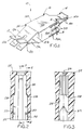
- FIGURE 2 is a fragmented axial section through a passageway in a connector housing for receiving the terminal of Figure 1;
- FIGURE 3 is a fragmented section taken generally along line 3-3 of Figure 2;
- FIGURE 4 is a fragmented section taken generally along line 4-4 of Figure 2;
- FIGURE 5 is a view similar to that of Figure 2, with a terminal in the terminal-receiving passageway, along with an insertion tool;
- FIGURE 6 is a section taken generally along line 6-6 of Figure 5, with the terminal having been inserted into the terminal-receiving passage by the insertion tool; and
- FIGURE 7 is a view similar to that of Figure 6, with the tool having spread apart and deformed the latch arms of the terminal into engagement with the latch shoulders of the housing.
- Referring to the drawings in greater detail, and first to Figure 1, a terminal, generally designated 10, is shown to incorporate the concepts of the invention. The terminal includes a mating end, generally designated 12, a terminating end, generally designated 14, and an intermediate body portion, generally designated 16, between the ends.
- Mating
end 12 ofterminal 10 is a female mating end for receiving a male terminal blade. Specifically, the mating end includes a pair of bifurcatedterminal arms 12a which are flared apart to define an entry mouth 12b into which a flat terminal blade is insertable. The blade is of a thickness to spreadterminal arms 12a and establish good contact with the arms in a contacting area 12c. - Terminating
end 14 ofterminal 10 includes a pair ofcontact arms 14a which can be spread apart, as at 14b, to provide some relative flexibility therebetween. Terminatingarms 14a are adapted to form solder tails for insertion into an appropriate hole in a printed circuit board for soldered electrical connection to circuit trace means on the board and/or in the hole. -
Intermediate body portion 16 ofterminal 10 is box-shaped as defined by opposite pairs ofside walls 16a and 16b. The box-shaped body portion defines a generally rectangular cavity therewithin and can be used as a contact in e.g. a fuse box for an automotive application. Of course, it should be understood that the precise configuration and use ofterminal 10 is not intended to be limiting, because the broader concepts of the invention have applicability for a wide range of terminal shapes or configurations. - Specifically, the invention contemplates that
terminal 10 include at least one pair oflatch arms 20 which are permanently deformable into latching condition within a connector housing, as described hereinafter. As seen in Figure 1, a pair oflatch arms 20 are stamped and formed out of one or bothwalls 16a on one or both opposite sides ofbody portion 16 ofterminal 10. The latch arms have necked-downbase areas 20a about which the arms primarily are deformed. With this configuration, the latch arms comprise generally planar portions generally coplanar withside walls 16a. As will be described in greater detail hereinafter, the latch arms are permanently deformable in a direction generally parallel to the planes of the arms, as indicated by arrows "A" in Figure 1. - In other words, most latch arms or locking fingers of previous stamped and formed metal terminals have been flexible or resilient about the bases or roots of the arms in a direction generally perpendicular to the planes of the arms. Therefore, the arms flex in one direction and spring back to their initial or latching positions. This is in contrast to the concepts of the invention wherein
latch arms 20 are intended to be deformed 'permanently". In other words, it is not intended for the latch arms to spring back to any initial or insertion positions. - Referring to Figures 2-4, the invention contemplates an electrical connector which includes a dielectric housing, generally designated 22, having at least one terminal-receiving
passageway 24 defining a terminal-insertion axis 26 (Fig. 3). Although the dielectric housing may include a plurality of terminal-receivingpassages 24, the following description will refer to the one illustratedpassageway 24 in conjunction with one of theterminals 10. - More particularly, each
passageway 24 includes a pair of stop shoulders 28 on one or both opposite sides of the passageway, latchshoulders 30 on opposite sides of the passageway and tool-receivingrecesses 32 on opposite sides of the passageway, all for purposes described below. Briefly, stopshoulders 28 engage ledges 34 (Fig. 1) ofterminal 10, latch shoulders 30 engage the distal ends oflatch arms 20, and recesses 32 provide adequate accommodation for an insertion and deforming tool as will be described below in relation to Figures 6 and 7. - Referring to Figures 5 and 6, terminal 10 in inserted into
passageway 24 in the direction of arrows "B". The terminals are inserted by an insertion and deformingtool 40 which has a triangulated end as seen best at 42 in Figure 6. The tool also has a central recessedarea 44 as seen best in Figure 5. The terminal is engaged by triangulatedend 42 of the tool as seen in Figure 6, whereby the terminal is inserted in the direction of arrows "B" untilledges 34 on the terminal engagestop shoulders 28 within the housing passageway as seen best in Figure 5. This defines the fully inserted position of the terminal. -
Tool 40 then is forced further againstlatch arms 20 in the direction of arrow "C" as illustrated in Figure 7. The triangulated configuration atend 42 of the tool is effective to permanently deform the latch arms by spreading the latch arms apart in the direction of arrows "D". The latch arms are deformed outwardly such that the distal ends of the latch arms seat tightly against latch shoulders 30 ofhousing 22 withinpassageway 24. When the tool is moved to deformlatch arms 20, recess 44 (Fig. 5) within the end of the tool accommodates terminatingarms 14a of the terminal. In addition, recesses 32 on opposite sides ofpassageway 24 accommodate the full width oftool 40 to ensure that there is adequate area on the triangulated end portions of the tool to engage and deform the thinmetal latch arms 20 of the terminal. When the tool is removed, the latch arms remain permanently deformed in engagement with latch shoulders 30. - It will be understood that the invention may be embodied in other specific forms without departing from the spirit or central characteristics thereof. The present examples and embodiments, therefore, are to be considered in all respects as illustrative and not restrictive, and the invention is not to be limited to the details given herein.
Claims (13)
- In an electrical connector which includes a dielectric housing (22) having a terminal-receiving passageway (24) defining a terminal-insertion axis (26), the housing including a latch shoulder (30) in the passageway, a terminal (10) insertable along said axis into the passageway, and the terminal including latch means (20) for latching behind the latch shoulder (30) to prevent removal of the terminal from the passageway (24),
wherein the improvement in said latch means comprises:
a latch arm (20) which is permanently deformable from a first, insertion position to permit insertion of the terminal (10) into the passageway (24) and a second, latching position transversely of the axis (26) from the first position into engagement with the latch shoulder (30) to prevent removal of the terminal from the passageway. - In an electrical connector as set forth in claim 1, wherein said terminal (10) is a stamped and formed member of sheet metal material, said latch arm (20) being a generally planar portion of the terminal and being deformable in a direction generally parallel to the plane of the arm.
- In an electrical connector as set forth in claim 1, wherein said terminal (10) includes a mating end (12), a terminating end (14) and an intermediate body portion (16) therebetween, the latch arm being on the body portion.
- In an electrical connector as set forth in claim 4, wherein said body portion (16) is generally box-shaped as defined by a plurality of side walls (16a,16b), the latch arm being on one of the side walls (16a).
- In an electrical connector as set forth in claim 1, wherein the dielectric housing (22) has a pair of said latch shoulders (30) generally on opposite sides of the passageway (24), and including a pair of said deformable latch arms (20) spreadable into latching engagement with the latch shoulders.
- In an electrical connector as set forth in claim 1, wherein said terminal (10) is a stamped member of sheet metal material, said latch arm (20) being a generally planar cantilevered component deformable in a direction generally parallel to the plane of the arm.
- In an electrical connector as set forth in claim 1, including complementary interengaging stop means (28,34) between the latch arm (20) and the housing (22) within the passageway (24) to define a fully inserted position of the terminal.
- An electrical connector, comprising:
a dielectric housing (22) including a terminal-receiving passageway (24) defining a terminal-insertion axis (26), the housing including stop shoulder means (28) within the passageway and a pair of latch shoulders (30) on opposite sides of the passageway; and
a terminal (10) insertable along said axis into the passageway, the terminal being stamped and formed of sheet metal material and including a mating end (12), a terminating end (14) and an intermediate body portion (16) between the ends, the body portion being generally box-shaped as defined by a plurality of side walls (16a,16b), at least one of the side walls (16a) including a pair of latch arms (20) which are permanently deformable from first, insertion positions to permit insertion of the terminal into the passageway and second latching positions transversely of the axis from the first positions into engagement with the latch shoulders (30) to prevent removal of the terminal (10) from the passageway (24), the terminal including ledge means (34) engageable with said stop shoulder means (28) to define a fully inserted position of the terminal. - An electrical connector as set forth in claim 8 wherein said latch arms (20) are generally planar portions of the terminal and are deformable in directions generally parallel to the respective planes of the arms.
- A method of assembling an electrical connector, comprising the steps of:
providing a dielectric housing (22) with a terminal-receiving passageway (24) and a latch shoulder (30) within the passageway;
providing a terminal (10) insertable into the passageway (24) and including a deformable latch arm (20);
inserting the terminal (10) into the terminal-receiving passageway (24); and
permanently deforming the latch arm (20) into engagement with the latch shoulder (30) to prevent removal of the terminal from the passageway. - The method of claim 10, including stamping and forming said terminal (10) from sheet metal material with said latch arm (20) being a generally planar portion of the terminal, and said deforming step comprises deforming the latch arm in a direction generally parallel to the plane of the arm.
- In an electrical connector which includes a dielectric housing (22) having a terminal-receiving passageway (24), the housing including latch surfaces means (30) in the passageway, a terminal (10) insertable in to the passageway, and the terminal including latch means (20) for latching behind the latch surface means (30) to prevent removal of the terminal from the passageway,
wherein the improvement in said latch means comprises:
a latch arm (20) which is permanently deformable into engagement with the latch surface means (30) to prevent removal of the terminal (10) from the passageway (24). - In an electrical connector as set forth in claim 12, wherein said terminal (10) is a stamped and formed member of sheet metal material, said latch arm (20) being a generally planar portion of the terminal and being deformable in a direction generally parallel to the plane of the arm.
Priority Applications (2)
| Application Number | Priority Date | Filing Date | Title |
|---|---|---|---|
| DE1993618840 DE69318840T2 (en) | 1993-10-22 | 1993-10-22 | Electrical connector with improved connection means |
| EP19930117133 EP0654855B1 (en) | 1993-10-22 | 1993-10-22 | Electrical connector with improved terminal retention means |
Applications Claiming Priority (1)
| Application Number | Priority Date | Filing Date | Title |
|---|---|---|---|
| EP19930117133 EP0654855B1 (en) | 1993-10-22 | 1993-10-22 | Electrical connector with improved terminal retention means |
Publications (2)
| Publication Number | Publication Date |
|---|---|
| EP0654855A1 true EP0654855A1 (en) | 1995-05-24 |
| EP0654855B1 EP0654855B1 (en) | 1998-05-27 |
Family
ID=8213363
Family Applications (1)
| Application Number | Title | Priority Date | Filing Date |
|---|---|---|---|
| EP19930117133 Expired - Lifetime EP0654855B1 (en) | 1993-10-22 | 1993-10-22 | Electrical connector with improved terminal retention means |
Country Status (2)
| Country | Link |
|---|---|
| EP (1) | EP0654855B1 (en) |
| DE (1) | DE69318840T2 (en) |
Cited By (2)
| Publication number | Priority date | Publication date | Assignee | Title |
|---|---|---|---|---|
| DE102010033173A1 (en) * | 2010-08-03 | 2012-02-09 | Phoenix Contact Gmbh & Co. Kg | Contact element i.e. insulation displacement connector contact for arrangement in connector socket, has snap-in element for fastening contact element within connection socket, where snap-in element includes spring arms |
| CN110581398A (en) * | 2013-09-19 | 2019-12-17 | 泰连公司 | Power terminal connector |
Citations (3)
| Publication number | Priority date | Publication date | Assignee | Title |
|---|---|---|---|---|
| GB1034599A (en) * | 1964-05-29 | 1966-06-29 | Cherry Electrical Prod | Housing for an electrical device |
| US3500299A (en) * | 1968-02-29 | 1970-03-10 | Conalco Metals Inc | Electrical plug and pin structure |
| EP0545529A2 (en) * | 1991-11-30 | 1993-06-09 | Nec Corporation | Electrical connector |
-
1993
- 1993-10-22 EP EP19930117133 patent/EP0654855B1/en not_active Expired - Lifetime
- 1993-10-22 DE DE1993618840 patent/DE69318840T2/en not_active Expired - Fee Related
Patent Citations (3)
| Publication number | Priority date | Publication date | Assignee | Title |
|---|---|---|---|---|
| GB1034599A (en) * | 1964-05-29 | 1966-06-29 | Cherry Electrical Prod | Housing for an electrical device |
| US3500299A (en) * | 1968-02-29 | 1970-03-10 | Conalco Metals Inc | Electrical plug and pin structure |
| EP0545529A2 (en) * | 1991-11-30 | 1993-06-09 | Nec Corporation | Electrical connector |
Cited By (4)
| Publication number | Priority date | Publication date | Assignee | Title |
|---|---|---|---|---|
| DE102010033173A1 (en) * | 2010-08-03 | 2012-02-09 | Phoenix Contact Gmbh & Co. Kg | Contact element i.e. insulation displacement connector contact for arrangement in connector socket, has snap-in element for fastening contact element within connection socket, where snap-in element includes spring arms |
| DE102010033173A9 (en) | 2010-08-03 | 2012-03-08 | Phoenix Contact Gmbh & Co. Kg | Contact element for arrangement in a connection socket |
| DE102010033173B4 (en) * | 2010-08-03 | 2012-05-24 | Phoenix Contact Gmbh & Co. Kg | Contact element for arrangement in a connection socket |
| CN110581398A (en) * | 2013-09-19 | 2019-12-17 | 泰连公司 | Power terminal connector |
Also Published As
| Publication number | Publication date |
|---|---|
| DE69318840T2 (en) | 1998-09-24 |
| DE69318840D1 (en) | 1998-07-02 |
| EP0654855B1 (en) | 1998-05-27 |
Similar Documents
| Publication | Publication Date | Title |
|---|---|---|
| US3550067A (en) | Electrical receptacle and terminal | |
| EP0795929B1 (en) | Electric connector assembly with improved retention characteristics | |
| US5080611A (en) | Boardlock for common-hole double-sided mounting | |
| EP0568971B1 (en) | Electrical connector with contact anti-overstress means | |
| JP3066712B2 (en) | Electrical connector | |
| EP0952632A2 (en) | Electrical connector with inserted terminals | |
| US5263882A (en) | Electrical connector with improved terminal retention means | |
| US4428633A (en) | Dual-in-line socket assembly | |
| WO1997045896A1 (en) | Surface mountable electrical connector | |
| EP0472006A1 (en) | Electrical terminal with means to insure that a positive electrical connection is effected | |
| EP1120861A2 (en) | Electrical connector having an improved female contact | |
| JPH1021981A (en) | Electric connector for substrate | |
| US3523273A (en) | Electrical connectors | |
| US4298242A (en) | Electrical socket contact | |
| EP0632549B1 (en) | Electrical connector assembly | |
| US4003617A (en) | Solderless electrical connector for printed circuit | |
| US6604966B1 (en) | Flexible cable electrical connector | |
| JP3898643B2 (en) | Small board to board connector | |
| JP3691294B2 (en) | Electrical connector | |
| US20030073339A1 (en) | Insulation displacement electrical connector | |
| EP0654855B1 (en) | Electrical connector with improved terminal retention means | |
| US20010003689A1 (en) | Electrical connector with terminal retainer | |
| EP0349154A2 (en) | Electrical terminal and connector for bladed fuse | |
| EP0700127A2 (en) | Shunt connector assembly | |
| US5178564A (en) | Electrical connector with solder mask |
Legal Events
| Date | Code | Title | Description |
|---|---|---|---|
| PUAI | Public reference made under article 153(3) epc to a published international application that has entered the european phase |
Free format text: ORIGINAL CODE: 0009012 |
|
| AK | Designated contracting states |
Kind code of ref document: A1 Designated state(s): DE ES FR GB IT SE |
|
| 17P | Request for examination filed |
Effective date: 19951118 |
|
| 17Q | First examination report despatched |
Effective date: 19960624 |
|
| GRAG | Despatch of communication of intention to grant |
Free format text: ORIGINAL CODE: EPIDOS AGRA |
|
| GRAG | Despatch of communication of intention to grant |
Free format text: ORIGINAL CODE: EPIDOS AGRA |
|
| GRAH | Despatch of communication of intention to grant a patent |
Free format text: ORIGINAL CODE: EPIDOS IGRA |
|
| GRAH | Despatch of communication of intention to grant a patent |
Free format text: ORIGINAL CODE: EPIDOS IGRA |
|
| GRAA | (expected) grant |
Free format text: ORIGINAL CODE: 0009210 |
|
| ITF | It: translation for a ep patent filed |
Owner name: DATA SOLLECITO LETT. INC.:02/10/98;DE DOMINICIS & |
|
| AK | Designated contracting states |
Kind code of ref document: B1 Designated state(s): DE ES FR GB IT SE |
|
| PG25 | Lapsed in a contracting state [announced via postgrant information from national office to epo] |
Ref country code: ES Free format text: THE PATENT HAS BEEN ANNULLED BY A DECISION OF A NATIONAL AUTHORITY Effective date: 19980527 |
|
| REF | Corresponds to: |
Ref document number: 69318840 Country of ref document: DE Date of ref document: 19980702 |
|
| ET | Fr: translation filed | ||
| PG25 | Lapsed in a contracting state [announced via postgrant information from national office to epo] |
Ref country code: SE Free format text: LAPSE BECAUSE OF FAILURE TO SUBMIT A TRANSLATION OF THE DESCRIPTION OR TO PAY THE FEE WITHIN THE PRESCRIBED TIME-LIMIT Effective date: 19980827 |
|
| PLBE | No opposition filed within time limit |
Free format text: ORIGINAL CODE: 0009261 |
|
| STAA | Information on the status of an ep patent application or granted ep patent |
Free format text: STATUS: NO OPPOSITION FILED WITHIN TIME LIMIT |
|
| 26N | No opposition filed | ||
| PGFP | Annual fee paid to national office [announced via postgrant information from national office to epo] |
Ref country code: DE Payment date: 20011030 Year of fee payment: 9 |
|
| REG | Reference to a national code |
Ref country code: GB Ref legal event code: IF02 |
|
| PGFP | Annual fee paid to national office [announced via postgrant information from national office to epo] |
Ref country code: GB Payment date: 20020913 Year of fee payment: 10 |
|
| PGFP | Annual fee paid to national office [announced via postgrant information from national office to epo] |
Ref country code: FR Payment date: 20021003 Year of fee payment: 10 |
|
| PG25 | Lapsed in a contracting state [announced via postgrant information from national office to epo] |
Ref country code: DE Free format text: LAPSE BECAUSE OF NON-PAYMENT OF DUE FEES Effective date: 20030501 |
|
| PG25 | Lapsed in a contracting state [announced via postgrant information from national office to epo] |
Ref country code: GB Free format text: LAPSE BECAUSE OF NON-PAYMENT OF DUE FEES Effective date: 20031022 |
|
| GBPC | Gb: european patent ceased through non-payment of renewal fee |
Effective date: 20031022 |
|
| PG25 | Lapsed in a contracting state [announced via postgrant information from national office to epo] |
Ref country code: FR Free format text: LAPSE BECAUSE OF NON-PAYMENT OF DUE FEES Effective date: 20040630 |
|
| REG | Reference to a national code |
Ref country code: FR Ref legal event code: ST |
|
| PG25 | Lapsed in a contracting state [announced via postgrant information from national office to epo] |
Ref country code: IT Free format text: LAPSE BECAUSE OF NON-PAYMENT OF DUE FEES;WARNING: LAPSES OF ITALIAN PATENTS WITH EFFECTIVE DATE BEFORE 2007 MAY HAVE OCCURRED AT ANY TIME BEFORE 2007. THE CORRECT EFFECTIVE DATE MAY BE DIFFERENT FROM THE ONE RECORDED. Effective date: 20051022 |