EP0654854B1 - Electrical terminal and method of fabricating same - Google Patents
Electrical terminal and method of fabricating same Download PDFInfo
- Publication number
- EP0654854B1 EP0654854B1 EP94118152A EP94118152A EP0654854B1 EP 0654854 B1 EP0654854 B1 EP 0654854B1 EP 94118152 A EP94118152 A EP 94118152A EP 94118152 A EP94118152 A EP 94118152A EP 0654854 B1 EP0654854 B1 EP 0654854B1
- Authority
- EP
- European Patent Office
- Prior art keywords
- contact
- floor
- base portion
- contact floor
- bight
- Prior art date
- Legal status (The legal status is an assumption and is not a legal conclusion. Google has not performed a legal analysis and makes no representation as to the accuracy of the status listed.)
- Expired - Lifetime
Links
Images


Classifications
-
- H—ELECTRICITY
- H01—ELECTRIC ELEMENTS
- H01R—ELECTRICALLY-CONDUCTIVE CONNECTIONS; STRUCTURAL ASSOCIATIONS OF A PLURALITY OF MUTUALLY-INSULATED ELECTRICAL CONNECTING ELEMENTS; COUPLING DEVICES; CURRENT COLLECTORS
- H01R43/00—Apparatus or processes specially adapted for manufacturing, assembling, maintaining, or repairing of line connectors or current collectors or for joining electric conductors
- H01R43/16—Apparatus or processes specially adapted for manufacturing, assembling, maintaining, or repairing of line connectors or current collectors or for joining electric conductors for manufacturing contact members, e.g. by punching and by bending
-
- H—ELECTRICITY
- H01—ELECTRIC ELEMENTS
- H01R—ELECTRICALLY-CONDUCTIVE CONNECTIONS; STRUCTURAL ASSOCIATIONS OF A PLURALITY OF MUTUALLY-INSULATED ELECTRICAL CONNECTING ELEMENTS; COUPLING DEVICES; CURRENT COLLECTORS
- H01R13/00—Details of coupling devices of the kinds covered by groups H01R12/70 or H01R24/00 - H01R33/00
- H01R13/02—Contact members
- H01R13/15—Pins, blades or sockets having separate spring member for producing or increasing contact pressure
- H01R13/187—Pins, blades or sockets having separate spring member for producing or increasing contact pressure with spring member in the socket
-
- Y—GENERAL TAGGING OF NEW TECHNOLOGICAL DEVELOPMENTS; GENERAL TAGGING OF CROSS-SECTIONAL TECHNOLOGIES SPANNING OVER SEVERAL SECTIONS OF THE IPC; TECHNICAL SUBJECTS COVERED BY FORMER USPC CROSS-REFERENCE ART COLLECTIONS [XRACs] AND DIGESTS
- Y10—TECHNICAL SUBJECTS COVERED BY FORMER USPC
- Y10T—TECHNICAL SUBJECTS COVERED BY FORMER US CLASSIFICATION
- Y10T29/00—Metal working
- Y10T29/49—Method of mechanical manufacture
- Y10T29/49002—Electrical device making
- Y10T29/49117—Conductor or circuit manufacturing
- Y10T29/49204—Contact or terminal manufacturing
- Y10T29/49208—Contact or terminal manufacturing by assembling plural parts
- Y10T29/49218—Contact or terminal manufacturing by assembling plural parts with deforming
-
- Y—GENERAL TAGGING OF NEW TECHNOLOGICAL DEVELOPMENTS; GENERAL TAGGING OF CROSS-SECTIONAL TECHNOLOGIES SPANNING OVER SEVERAL SECTIONS OF THE IPC; TECHNICAL SUBJECTS COVERED BY FORMER USPC CROSS-REFERENCE ART COLLECTIONS [XRACs] AND DIGESTS
- Y10—TECHNICAL SUBJECTS COVERED BY FORMER USPC
- Y10T—TECHNICAL SUBJECTS COVERED BY FORMER US CLASSIFICATION
- Y10T29/00—Metal working
- Y10T29/49—Method of mechanical manufacture
- Y10T29/49002—Electrical device making
- Y10T29/49117—Conductor or circuit manufacturing
- Y10T29/49204—Contact or terminal manufacturing
- Y10T29/49208—Contact or terminal manufacturing by assembling plural parts
- Y10T29/49222—Contact or terminal manufacturing by assembling plural parts forming array of contacts or terminals
Definitions
- the present invention relates to an electrical terminal and to a method for fabricating that terminal. More particularly, the present invention relates to an electrical terminal and a method of fabricating that terminal wherein the terminal is a female terminal utilizing a contact spring to urge an inserted male contact blade into contact with a contact floor which is unitary with the female terminal.
- electrical terminals should maintain good contact when connected, while allowing the terminals to be easily both initially connected, and subsequently disconnected and then reconnected, perhaps a number of times. Over time, many currently available electrical terminals fail to continuously transmit adequate current and, from time to time, fail when being disconnected and reconnected.
- U.S. Patent 4,560,231 provides an electrical contact which is stamped or punched from a thin sheet of metal. In forming the contact, part of the sheet is bent back on itself to form a resilient spring located to urge a pin received in the contact against an abutting portion of said contact.
- a female electrical terminal including a crimp at a first end for crimping a wire lead thereto, a socket at a second end for receiving a male contact pin, the socket including a base portion and flanges extending upward and inward to overlie the base portion, and a contact overlying the base portion and joined thereto by a bight, characterized in that the contact is a cantilevered floor extending from said bight to a free end, in that a separate spring biased contact is disposed within the socket in opposed relation to the contact floor for urging a male contact pin into abutment with the contact floor, and in that said contact floor has a pair of longitudinally extending peripheral foot flanges depending from side edges thereof and projecting toward the base portion.
- a method of forming a female electrical terminal wherein the socket is formed from a unitary blank by: a) folding a pair of side flanges to extend substantially normal with respect to a base portion to form a channel; b) folding a pair of peripheral foot flanges, depending from the side edges of the contact floor, to extend substantially normal with respect to a contact floor; c) bending the contact floor about a bight thereof into alignment with the channel so as to overlie the base portion and such that the peripheral foot flanges project toward the base portion; d) while folding the contact floor, supporting the contact floor continuously at the bight thereof, and e) bending the side flanges so that free ends thereof overlie the contact floor, in spaced relation with respect thereto to form a space therebetween for receiving a contact spring.
- a female electrical terminal 10 for connecting an electrical wire lead 12 to a male contact blade 14.
- the female electrical terminal 10 retains the wire lead 12 by first and second pairs of crimp flanges 16 and 18 which are crimped over the wire lead 12 and its insulation 19, respectively, at a first end 20 of the female terminal.
- a socket 24 At a second end 22 of the female terminal 10, there is disposed a socket 24 having a spring biased contact surface 26 therein.
- the spring biased contact surface 26 is unitary with, and biased by, a bowed steel spring 28 having two arms 29 and 30 which urge the contact surface 26 into abutment with the male contact pin 14.
- Beneath the male contact pin 14 is a cantilevered contact floor 31.
- FIG. 3 there is shown a strip 40 having a plurality of the female electrical terminals 10 mounted thereon for folding by the fabrication machinery of Figures 8-13. As the strip 40 is advanced, various unitary sections of the female electrical terminal 10 are folded over one another so that the female terminal is ready to receive the wire lead 12 (Fig. 1), the spring biased contact 26 (Fig. 1) and ultimately the male contact pin 14 (Fig. 1).
- the female electrical terminal 10 is shown enlarged as a blank 41 before folding, it is seen that the second end 22 which is folded to form the socket 24 for receiving the male contact pin blade 14 includes first and second side flanges 44 and 46.
- the first and second side flanges 44 and 46 each include, respectively, windows 48 and 50 as well as embossments 52 and 54 which form raised shelves.
- a large window 56 is disposed in a front base portion 57 of the terminal 10.
- fold areas 58 and 60 are fold areas which, as is seen in Figures 5 and 6, allow the side flanges 44 and 46 to be bent up out of the plane of the terminal blank shown in Figure 4.
- the flanges 44 and 46 have leading edges 62 and 64 and trailing edges 66 and 68.
- the leading edges 62 and 64 also intersect with a fold line 70 which extends perpendicular to the fold lines 58 and 60 so as to allow the cantilevered contact floor 31 to fold approximately 180° over the front base portion 57 of the female terminal 10 in overlying relation to the large window 56 (see Fig. 1).
- the cantilevered contact floor 31 has a bottom surface 72 having a pair of longitudinally extending feet or foot flanges 74 and 76 extending substantially perpendicularly therefrom (see Figures 2 and 15).
- the cantilevered contact floor 31 also has a pair of contacting ribs 77 and 78 which are formed therein by embossing the contact floor before it is folded.
- the contact ribs 77 and 78 extend longitudinally on the contact floor 31 and have flattened shallow portions 79 proximate fold line 70. When the female terminal 10 is assembled, the contacting ribs 77 and 78 contact the male contact pin 14 (see Figure 1).
- the cantilevered contact floor 31 and the side flanges 44 and 46 are bent upwardly from the front base portion 57 and in Figure 6, the cantilevered contact floor is bent to overlie the contact front base portion. If the cantilevered contact floor 31 is bent from the position of Figure 4, through the position of Figure 5 to that of Figure 6, then the bight 80 of the resulting U-shaped configuration is subject to "orange peeling" due to stress cracks rather randomly formed as the cantilevered contact floor 31 is bent. These random cracks substantially reduce the amount of current that the terminal can carry. By employing features of the present invention, as is set forth in Figures 8-13, orange peeling is substantially avoided and the current carrying capacity of the entire terminal 10 is enhanced.
- the terminal of the present invention is configured differently from the terminal of the prior art shown in Figure 7, wherein a tab 81 projects downwardly from the cantilevered contact floor 31' and engages the front base portion 57'.
- the tab 81 prevents the bight portion 80' of the prior art cantilevered contact floor 31' from being supported internally as it is bent and therefore results in a terminal with stress cracks at the bight which lower the current carrying capacity of prior art terminals.
- the cantilevered contact floor 31 of the present invention has a free end instead of an end with a tab.
- the feet 74 and 76 extend from the sides of the contact floor 31 toward the front base portion 57.
- FIG 8 where the blank 41 of the terminal 10 (also see Figures 3 and 4) is shown being bent in accordance with the principles of the instant invention, it is seen that the blank 41 is supported on a die shoe 90 having a flat surface 92 for supporting the blank 41.
- a die punch 92 with a flat surface 94 retains the blank 41 against the die shoe 90.
- the die punch 92 has an overhanging projecting portion 96 which projects beyond a die surface 98 on the die shoe 90.
- the die punch also includes a forming surface 100 which projects at a 60° angle with respect to the blank 41 or a 120° angle with respect to the surface 94.
- a first die 102 is advanced in the direction of an arrow 104 to engage and bend the cantilevered contact floor with an angled surface 108.
- the angled surface 108 also extends at 60° with respect to the extent of the blank 41 and includes a section 110 joined to the surface 105 by a corner 111.
- the die punch 92 has a width which is less than the space between the feet 74 and 76 of the cantilevered contact floor.
- the first bend is about 60° so that the cantilevered contact floor 31 is at an angle of about 120° with respect to the front base portion 57 of the blank 41.
- the blank 41 is supported by the die shoe 90 and also by a second die punch 120 which now clamps the blank 41 further outboard of the die shoe.
- the die punch 120 has a die punch surface 122 which is perpendicular to a bottom surface 124 opposed to the upper surface 92 of the die shoe 90 and includes a curved corner 124 around which the bend 126 in the blank 41 is formed.
- Opposing the die punch 120 is a second die 130 having a die face 132 parallel to the surface 124 of the die punch and a die face 134 perpendicular to the die face 132.
- the two die faces are joined by a curved die corner 136 which complements the curved die corner 124 on the die punch 120 as the second die 130 moves in the direction of the arrow 138 to bend the cantilevered contact floor 31 substantially normal to the floor portion 57 of blank 41.
- a land 140 projects from the die face 134 to provide space for accommodating the thickness t on the cantilevered contact floor 31.
- the die punch 120 has a width which fits between the feet 74 and 76 on the cantilevered contact floor 31.
- the second bend is about 30° so that the cantilevered contact floor 31 is at about 90° to the front base portion 57 of the blank 41.
- the blank 41 is shown with the cantilevered contact floor 31 extending perpendicular to the front base portion 57 of the blank 41 after being bent in accordance with the step of Figure 9.
- the blank 41 is still supported by the die shoe 90; however, a mandrel 150, having a triangular projection 152 with a 30° face 154 and a bottom face 156, is used to bend the cantilevered contact floor 31 about a curved nose 158.
- the mandrel 150 travels in the direction 160.
- a third die 164 has a first horizontal die face 166 and an angled die face 168 disposed at 60° with respect to the face 166, the die faces 166 and 168 being joined by an arcuate bight 170.
- the third die 164 advances in the direction of arrow 172 toward the mandrel 150, while the mandrel advances toward the die 164 in the direction of arrow 173.
- the curved faces 158 and 170 bend the blank 41 at area 174 which forms the bight 80 so as to assume the 30° bend of Figure 11.
- the third bend is therefore about 60°.
- a die shoe 180 now has a configuration wherein a first flat supporting surface 182 supports the blank 41 and is joined by a second surface 184 which is substantially parallel to the first surface 182.
- the second flat surface 184 joins the first surface with a concave surface 186.
- the bight portion 80 of the blank 41 is urged against the concave curved portion 186 by a second mandrel 190 which has a curved nose portion 192 that complements the curvature of both the curved die portion 186 and the bight 80 of the blank 41.
- a die punch 190 has a first flat 192 in opposition to the flat 182 on the die shoe 180 and a second flat 194 in opposition to the second flat 184 in the die shoe.
- the flats 192 and 194 are joined by concave curve 196.
- the die punch 196 advances in the direction of arrow 200 toward the die shoe to bend the cantilevered contact floor about 30° so that it extends substantially parallel with the front base portion 57.
- the die punch 190 bends the cantilevered contact floor 31 over so that it extends substantially parallel to the front base portion 57 of the blank 41. As this final bend is performed, the cantilevered contact floor 31 is supported by the curved nose 192 of the mandrel 190.
- the die punch 196 is then raised in the direction of arrow 202, while the mandrel 190 is withdrawn in the direction of arrow 204.
- the bight 80 joining the cantilevered contact floor 31 to front base portion 57 has been substantially supported during the entire formation of the bend disposing the cantilevered contact floor substantially parallel to front base portion 57 of the blank 41, the resulting bight results in a female terminal 10 which has enhanced reliability.
- the spring arms 29 and 30 have relatively small contact areas with the surfaces of the folded flanges 44 and 46 compared to the relatively large contact area provided by the contacting ribs 78 and 79 of the cantilevered contact floor 31. If the bight portion 80 of the cantilevered contact floor 31 fractures or develops cracks due to the bending of the contact floor during fabrication, then its efficiency for transmitting current is reduced. If the actual connecting area is substantially reduced, then the current flowing around the bight portion 80 may be channeled through metal of small cross-sectional area. This can result in these cross-sectional areas heating and, after a time, rupturing.
- the spring arms 29 and 30 of the contact spring 26 have tabs 220 and 222 which extend through the small windows 40 and 58, respectively, to retain the spring arms.
- the spring arms are additionally supported on the shelves 52 and 54.
- the side flanges 44 and 46 are then again folded at fold lines 230 and 232 so that upper portions 234 and 236 of the side flanges overlie the unitary, spring contact surface 26 and retain the contact surface and its associated spring arms 29 and 30 within the socket 24.
- a pair of end flanges 238 and 240 on the top portions 234 and 236 of the side flanges 44 and 46 engage the spring arm 28 so that the unitary, spring contact surface 26 does not slide out of the socket 24 when the male contact pin 14 is withdrawn therefrom.
- FIG 16 there is shown an enlarged view of the fabricated and assembled female terminal 10 receiving the male contact pin 14 to connect the male contact pin to the wire lead 12.
- An example of the entire female terminal 10 has a length of about 3/4 inch (2 cm), a width of about 1/8 inch (0.5 cm) and a height of about 3/32 inch (0.2 cm).
Landscapes
- Engineering & Computer Science (AREA)
- Manufacturing & Machinery (AREA)
- Coupling Device And Connection With Printed Circuit (AREA)
- Manufacturing Of Electrical Connectors (AREA)
Description
- The present invention relates to an electrical terminal and to a method for fabricating that terminal. More particularly, the present invention relates to an electrical terminal and a method of fabricating that terminal wherein the terminal is a female terminal utilizing a contact spring to urge an inserted male contact blade into contact with a contact floor which is unitary with the female terminal.
- As automobiles increasingly rely on electrical components, the number of electrical terminals necessarily increases. In that the electrical components interact with one another, it is increasingly important that electrical connections be properly made so that each contact carries the current load which it is expected to transmit. In automobiles, electrical connections are frequently subjected to impacts and vibration due to the motion and vibration caused by both vehicular motion and engine operation. In addition, since many electrical components are proximate the engine of a vehicle, the components are subjected to heat. Moreover, moisture and road dirt can over time invade electrical terminals when from time to time the terminals are disconnected for maintenance purposes.
- Preferably, electrical terminals should maintain good contact when connected, while allowing the terminals to be easily both initially connected, and subsequently disconnected and then reconnected, perhaps a number of times. Over time, many currently available electrical terminals fail to continuously transmit adequate current and, from time to time, fail when being disconnected and reconnected.
- It is also highly desirable to maximize the current carrying capacity of electrical terminals so that their physical size may be minimized as well as their number.
- U.S. Patent 4,560,231 provides an electrical contact which is stamped or punched from a thin sheet of metal. In forming the contact, part of the sheet is bent back on itself to form a resilient spring located to urge a pin received in the contact against an abutting portion of said contact.
- In view of the aforementioned considerations, it is a feature of the instant invention to provide a new and improved electrical terminal in which a good, reliable electrical connection is maintained over a time with periodic disconnections and reconnections, which does not fail during either the fabrication process or upon initial coupling and which has increased current carrying capacity.
- According to the present invention there is provided a female electrical terminal including a crimp at a first end for crimping a wire lead thereto, a socket at a second end for receiving a male contact pin, the socket including a base portion and flanges extending upward and inward to overlie the base portion, and a contact overlying the base portion and joined thereto by a bight, characterized in that the contact is a cantilevered floor extending from said bight to a free end, in that a separate spring biased contact is disposed within the socket in opposed relation to the contact floor for urging a male contact pin into abutment with the contact floor, and in that said contact floor has a pair of longitudinally extending peripheral foot flanges depending from side edges thereof and projecting toward the base portion.
- According to a further aspect of the invention there is provided a method of forming a female electrical terminal, wherein the socket is formed from a unitary blank by: a) folding a pair of side flanges to extend substantially normal with respect to a base portion to form a channel; b) folding a pair of peripheral foot flanges, depending from the side edges of the contact floor, to extend substantially normal with respect to a contact floor; c) bending the contact floor about a bight thereof into alignment with the channel so as to overlie the base portion and such that the peripheral foot flanges project toward the base portion;
d) while folding the contact floor, supporting the contact floor continuously at the bight thereof, and e) bending the side flanges so that free ends thereof overlie the contact floor, in spaced relation with respect thereto to form a space therebetween for receiving a contact spring. - Various other objects, features and attendant advantages of the present invention will be more fully appreciated as the same becomes better understood when considered in conjunction with the accompanying drawings, in which like reference characters designate the same or similar parts throughout the several views, and wherein:
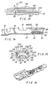
- Figure 1 is a side elevation illustrating a female electrical terminal in accordance with the instant invention crimped at one end to a wire lead and detachably connected at the other end with a contact blade of a male terminal;
- Figure 2 is a perspective view of the female electrical terminal with portions partially bent and with portions in phantom;
- Figure 3 is a top view of a strip with a plurality of female terminal blanks extending therefrom in various stages of fabrication;
- Figure 4 is an enlarged top view showing a cut blank from which the female electrical terminal is formed by bending;
- Figure 5 is an enlarged side view showing side flanges bent upward and a cantilevered contact floor being bent upward;
- Figure 6 is a view similar to Figure 5 showing the contact floor bent to a final position;
- Figure 7 is a view of a prior art contact floor;
- Figure 8 is a side elevation showing die faces holding the blank and advancing to fold the cantilevered contact floor to a first position in a first bending step;
- Figure 9 is a view similar to Figure 8 and showing second die faces folding the cantilevered contact floor to a second position in a second bending step;
- Figure 10 is a view similar to Figures 8 and 9 showing third die faces bending the cantilevered contact floor to a third position in a third bending step;
- Figures 11 and 12 are views similar to Figures 8-10 showing the cantilevered contact floor being bent to a fourth position in a fourth bending step;
- Figure 13 is a view similar to Figures 11 and 12 showing the dies releasing the finally formed cantilevered contact floor;
- Figure 14 is a side elevation of the female terminal after side flanges have been folded over to form a socket;
- Figure 15 is a front view of the assembled female terminal; and
- Figure 16 is an enlarged, perspective view of the assembled female terminal receiving the contact pin of a male terminal.
-
- Referring now to Figures 1 and 2, there is shown a female
electrical terminal 10 for connecting anelectrical wire lead 12 to amale contact blade 14. The femaleelectrical terminal 10 retains thewire lead 12 by first and second pairs ofcrimp flanges wire lead 12 and itsinsulation 19, respectively, at afirst end 20 of the female terminal. At asecond end 22 of thefemale terminal 10, there is disposed asocket 24 having a springbiased contact surface 26 therein. The springbiased contact surface 26 is unitary with, and biased by, a bowed steel spring 28 having twoarms contact surface 26 into abutment with themale contact pin 14. Beneath themale contact pin 14 is a cantileveredcontact floor 31. - In an electrical terminal of the type illustrated in Figures 1 and 2, 80%-90% of the current flows through the
cantilevered contact floor 31 into the body of the femaleelectrical terminal 10 so as to be transmitted through to thewire lead 12 via thecrimp 18 and arear bottom surface 34 of thefirst end 20 of theterminal 10. It is therefore very important that the electrical terminal between themale contact blade 14 and the cantileveredcontact floor 31 be adequately maintained and not deteriorate over time due to various mechanical and environmental factors. Moreover, it is important that cantileveredcontact floor 31 transmit as much current as possible. Therefore, it is desirable that the current carrying capacity of the cantileveredcontact floor 31 not be diminished during fabrication. - Referring now to Figure 3, there is shown a strip 40 having a plurality of the female
electrical terminals 10 mounted thereon for folding by the fabrication machinery of Figures 8-13. As the strip 40 is advanced, various unitary sections of the femaleelectrical terminal 10 are folded over one another so that the female terminal is ready to receive the wire lead 12 (Fig. 1), the spring biased contact 26 (Fig. 1) and ultimately the male contact pin 14 (Fig. 1). - Referring now to Figure 4 wherein the female
electrical terminal 10 is shown enlarged as a blank 41 before folding, it is seen that thesecond end 22 which is folded to form thesocket 24 for receiving the malecontact pin blade 14 includes first andsecond side flanges second side flanges windows embossments embossments large window 56 is disposed in afront base portion 57 of theterminal 10. Between thelarge window 56 andshelves fold areas side flanges - In order to facilitate bending, the
flanges edges trailing edges leading edges fold line 70 which extends perpendicular to thefold lines contact floor 31 to fold approximately 180° over thefront base portion 57 of thefemale terminal 10 in overlying relation to the large window 56 (see Fig. 1). The cantileveredcontact floor 31 has abottom surface 72 having a pair of longitudinally extending feet orfoot flanges contact floor 31 also has a pair of contactingribs contact floor 31 and have flattenedshallow portions 79proximate fold line 70. When thefemale terminal 10 is assembled, the contactingribs - In Figure 5, the cantilevered
contact floor 31 and theside flanges front base portion 57 and in Figure 6, the cantilevered contact floor is bent to overlie the contact front base portion. If the cantileveredcontact floor 31 is bent from the position of Figure 4, through the position of Figure 5 to that of Figure 6, then thebight 80 of the resulting U-shaped configuration is subject to "orange peeling" due to stress cracks rather randomly formed as the cantileveredcontact floor 31 is bent. These random cracks substantially reduce the amount of current that the terminal can carry. By employing features of the present invention, as is set forth in Figures 8-13, orange peeling is substantially avoided and the current carrying capacity of theentire terminal 10 is enhanced. - In order to facilitate the steps shown in Figures 8-13, the terminal of the present invention is configured differently from the terminal of the prior art shown in Figure 7, wherein a
tab 81 projects downwardly from the cantilevered contact floor 31' and engages the front base portion 57'. Thetab 81 prevents the bight portion 80' of the prior art cantilevered contact floor 31' from being supported internally as it is bent and therefore results in a terminal with stress cracks at the bight which lower the current carrying capacity of prior art terminals. The cantileveredcontact floor 31 of the present invention has a free end instead of an end with a tab. In the present invention, thefeet contact floor 31 toward thefront base portion 57. - Referring now to Figure 8 where the blank 41 of the terminal 10 (also see Figures 3 and 4) is shown being bent in accordance with the principles of the instant invention, it is seen that the blank 41 is supported on a
die shoe 90 having aflat surface 92 for supporting the blank 41. A diepunch 92 with aflat surface 94 retains the blank 41 against the dieshoe 90. The diepunch 92 has anoverhanging projecting portion 96 which projects beyond a die surface 98 on the dieshoe 90. The die punch also includes a formingsurface 100 which projects at a 60° angle with respect to the blank 41 or a 120° angle with respect to thesurface 94. In order to being folding the cantileveredcontact floor 31, afirst die 102 is advanced in the direction of anarrow 104 to engage and bend the cantilevered contact floor with anangled surface 108. Theangled surface 108 also extends at 60° with respect to the extent of the blank 41 and includes asection 110 joined to the surface 105 by a corner 111. Thedie punch 92 has a width which is less than the space between thefeet first die 102 bends the contact floor at alocation 112 juxtaposed with thecorner 114 on thedie punch 92 and thecorner 116 on thefirst die face 102, thefeet surface 100. The first bend is about 60° so that the cantileveredcontact floor 31 is at an angle of about 120° with respect to thefront base portion 57 of the blank 41. - Referring now to Figure 9, where the blank 41 is shown after the 120° bend in the cantilevered
contact floor 31 is introduced by the step of Figure 8, the blank 41 is supported by thedie shoe 90 and also by asecond die punch 120 which now clamps the blank 41 further outboard of the die shoe. Thedie punch 120 has adie punch surface 122 which is perpendicular to abottom surface 124 opposed to theupper surface 92 of thedie shoe 90 and includes acurved corner 124 around which thebend 126 in the blank 41 is formed. Opposing thedie punch 120 is asecond die 130 having adie face 132 parallel to thesurface 124 of the die punch and adie face 134 perpendicular to thedie face 132. The two die faces are joined by acurved die corner 136 which complements thecurved die corner 124 on thedie punch 120 as thesecond die 130 moves in the direction of thearrow 138 to bend the cantileveredcontact floor 31 substantially normal to thefloor portion 57 of blank 41. Aland 140 projects from thedie face 134 to provide space for accommodating the thickness t on the cantileveredcontact floor 31. Again, thedie punch 120 has a width which fits between thefeet contact floor 31. The second bend is about 30° so that the cantileveredcontact floor 31 is at about 90° to thefront base portion 57 of the blank 41. - Referring now to Figure 10, the blank 41 is shown with the cantilevered
contact floor 31 extending perpendicular to thefront base portion 57 of the blank 41 after being bent in accordance with the step of Figure 9. In Figure 10, the blank 41 is still supported by thedie shoe 90; however, amandrel 150, having a triangular projection 152 with a 30° face 154 and abottom face 156, is used to bend the cantileveredcontact floor 31 about acurved nose 158. Themandrel 150 travels in thedirection 160. Athird die 164 has a firsthorizontal die face 166 and anangled die face 168 disposed at 60° with respect to theface 166, the die faces 166 and 168 being joined by anarcuate bight 170. The third die 164 advances in the direction of arrow 172 toward themandrel 150, while the mandrel advances toward thedie 164 in the direction ofarrow 173. The curved faces 158 and 170 bend the blank 41 atarea 174 which forms thebight 80 so as to assume the 30° bend of Figure 11. The third bend is therefore about 60°. - Referring now to Figure 11, a
die shoe 180 now has a configuration wherein a first flat supportingsurface 182 supports the blank 41 and is joined by asecond surface 184 which is substantially parallel to thefirst surface 182. The secondflat surface 184 joins the first surface with aconcave surface 186. Thebight portion 80 of the blank 41 is urged against the concavecurved portion 186 by asecond mandrel 190 which has acurved nose portion 192 that complements the curvature of both thecurved die portion 186 and thebight 80 of the blank 41. Adie punch 190 has a first flat 192 in opposition to the flat 182 on thedie shoe 180 and a second flat 194 in opposition to the second flat 184 in the die shoe. Theflats 192 and 194 are joined byconcave curve 196. In operation, thedie punch 196 advances in the direction ofarrow 200 toward the die shoe to bend the cantilevered contact floor about 30° so that it extends substantially parallel with thefront base portion 57. - As is seen in Figure 12, the
die punch 190 bends the cantileveredcontact floor 31 over so that it extends substantially parallel to thefront base portion 57 of the blank 41. As this final bend is performed, the cantileveredcontact floor 31 is supported by thecurved nose 192 of themandrel 190. - As is seen in Figure 13, the
die punch 196 is then raised in the direction ofarrow 202, while themandrel 190 is withdrawn in the direction ofarrow 204. In that thebight 80 joining the cantileveredcontact floor 31 tofront base portion 57 has been substantially supported during the entire formation of the bend disposing the cantilevered contact floor substantially parallel tofront base portion 57 of the blank 41, the resulting bight results in afemale terminal 10 which has enhanced reliability. - As was previously stated, this is readily apparent because the orange peeling which occurs at the
bight 80 when the cantileveredcontact floor 31 is not formed with support at the bight, no longer occurs. It is of utmost importance that the contactingribs contact floor 31 remain, many times for years, in abutment with amale contact pin 14 under the urging of the contact spring 26 (see Figure 1). - As is perhaps best seen in Figure 1, the
spring arms flanges ribs contact floor 31. If thebight portion 80 of the cantileveredcontact floor 31 fractures or develops cracks due to the bending of the contact floor during fabrication, then its efficiency for transmitting current is reduced. If the actual connecting area is substantially reduced, then the current flowing around thebight portion 80 may be channeled through metal of small cross-sectional area. This can result in these cross-sectional areas heating and, after a time, rupturing. - It has been found that up to 90% of the current flows through the cantilevered
contact floor 31 and that, in a terminal made of copper alloy having a length of about 3/4 inch or 2 cm, a width of about 1/8 inch (0.5 cm) and a height of about 3/32 inch (0.2 cm), up to 50 amps of current is successfully conducted under ambient conditions and 40 amps of current successfully conducted without failure under shock conditions. This results in a terminal 10 which is under-rated at 25 amps. The prior art terminals have a shock rating of about 25 amps and are under-rated at 5-20 amps. when such terminals conduct only 20 amps, then there may be an increased risk of failure if the shock rating is only 25 amps. Accordingly, either many more terminals, or terminals of a larger size, are required in automotive installations when using the prior art terminals. Making terminals larger or using more terminals results in inherent design disadvantages over using smaller or fewer numbers of terminals. - Referring now to Figure 14, after the
floor portion 31 has been bent to the position of Figures 13 and 14, thecontact spring 26 is mounted between theupstanding side flanges contact spring 26 is inserted,flanges socket 24. Theflanges - As is seen in Figure 15, the
spring arms contact spring 26 havetabs small windows 40 and 58, respectively, to retain the spring arms. The spring arms are additionally supported on theshelves fold lines upper portions 234 and 236 of the side flanges overlie the unitary,spring contact surface 26 and retain the contact surface and its associatedspring arms socket 24. A pair ofend flanges top portions 234 and 236 of theside flanges spring contact surface 26 does not slide out of thesocket 24 when themale contact pin 14 is withdrawn therefrom. - Referring now to Figure 16, there is shown an enlarged view of the fabricated and assembled
female terminal 10 receiving themale contact pin 14 to connect the male contact pin to thewire lead 12. An example of the entirefemale terminal 10 has a length of about 3/4 inch (2 cm), a width of about 1/8 inch (0.5 cm) and a height of about 3/32 inch (0.2 cm).
Claims (8)
- A female electrical terminal (10) including a crimp (18) at a first end (20) for crimping a wire lead (12) thereto, a socket (24) at a second end (20) for receiving a male contact pin (14), the socket (24) including a base portion (57) and flanges (44,46) extending upward and inward to overlie the base portion (57), and a contact overlying the base portion (57) and joined thereto by a bight (80), characterized in that the contact is a cantilevered floor (31) extending from said bight (80) to a free end, in that a separate spring biased contact (26) is disposed within the socket (24) in opposed relation to the contact floor (31) for urging a male contact pin (14) into abutment with the contact floor (31), and in that said contact floor (31) has a pair of longitudinally extending peripheral foot flanges (74,76) depending from side edges thereof and projecting toward the base portion (51).
- A terminal (10) according to claim 1, characterized in that the contact floor (31) includes a pair of parallel, spaced ribs (78,79) extending in a direction away from the foot flanges (74,76), the ribs (78,79) being formed by embossments (52,54) which extend from the bight (80) toward the free end of the contact floor (31).
- An electrical terminal (10) according to claim 2, characterized in that the terminal is made of steel.
- A method of forming a female electrical terminal, wherein the socket is formed from a unitary blank by:a) folding a pair of side flanges to extend substantially normal with respect to a base portion to form a channel;b) folding a pair of peripheral foot flanges, depending from the side edges of a contact floor, to extend substantially normal with respect to the contact floor;c) bending the contact floor about a bight thereof into alignment with the channel so as to overlie the base portion and such that the peripheral foot flanges project toward the base portion;d) while folding the contact floor, supporting the contact floor continuously at the bight thereof, ande) bending the side flanges so that free ends thereof overlie the contact floor, in spaced relation with respect thereto to form a space therebetween for receiving a contact spring.
- A method according to claim 4, characterized in that the female electrical terminal (10) is made of steel.
- A method according to claim 4, characterized in that the contact floor (31) is bent in a series of discrete steps from a first orientation in which the contact floor (31) extends in the same direction as the base portion (57) to the position in which the contact floor (31) overlies the base portion (57).
- A method according to claim 6, characterized in that the discrete steps comprise a first discrete step of about 60°, a second discrete step of about 30°, a third discrete step of about 60°, and a fourth discrete step of about 30°.
- A method according to claim 7, characterized in that the female electrical terminal (10) is made of steel.
Applications Claiming Priority (2)
| Application Number | Priority Date | Filing Date | Title |
|---|---|---|---|
| US155506 | 1993-11-22 | ||
| US08/155,506 US5427552A (en) | 1993-11-22 | 1993-11-22 | Electrical terminal and method of fabricating same |
Publications (3)
| Publication Number | Publication Date |
|---|---|
| EP0654854A2 EP0654854A2 (en) | 1995-05-24 |
| EP0654854A3 EP0654854A3 (en) | 1996-08-07 |
| EP0654854B1 true EP0654854B1 (en) | 2002-08-07 |
Family
ID=22555720
Family Applications (1)
| Application Number | Title | Priority Date | Filing Date |
|---|---|---|---|
| EP94118152A Expired - Lifetime EP0654854B1 (en) | 1993-11-22 | 1994-11-17 | Electrical terminal and method of fabricating same |
Country Status (5)
| Country | Link |
|---|---|
| US (2) | US5427552A (en) |
| EP (1) | EP0654854B1 (en) |
| JP (1) | JPH07312252A (en) |
| CA (1) | CA2136252A1 (en) |
| DE (1) | DE69431147T2 (en) |
Cited By (1)
| Publication number | Priority date | Publication date | Assignee | Title |
|---|---|---|---|---|
| CN109546401A (en) * | 2017-09-21 | 2019-03-29 | 日本航空电子工业株式会社 | Female end and connector |
Families Citing this family (37)
| Publication number | Priority date | Publication date | Assignee | Title |
|---|---|---|---|---|
| JP3440539B2 (en) * | 1994-03-22 | 2003-08-25 | 矢崎総業株式会社 | Connector terminal locking structure and method of manufacturing terminal fitting |
| JP3533536B2 (en) * | 1994-07-11 | 2004-05-31 | 住友電装株式会社 | Female terminal fitting |
| JP3497615B2 (en) * | 1995-07-12 | 2004-02-16 | 矢崎総業株式会社 | Female terminal |
| US5800220A (en) * | 1995-10-23 | 1998-09-01 | Framatome Connectors Interlock Inc. | Tab receptacle terminal |
| US5626984A (en) * | 1995-11-16 | 1997-05-06 | Albini; Salvatore | Battery terminal system |
| US5658174A (en) * | 1995-12-01 | 1997-08-19 | Molex Incorporated | Female electrical terminal |
| US5810627A (en) * | 1996-01-11 | 1998-09-22 | Molex Incorporated | Female electrical terminal |
| US6216338B1 (en) | 1997-11-25 | 2001-04-17 | Micron Electronics, Inc. | Header pin pre-load apparatus |
| US6035529A (en) * | 1997-11-25 | 2000-03-14 | Micron Electronics, Inc. | Header pin pre-loaded method |
| US6036521A (en) * | 1998-03-20 | 2000-03-14 | Electrical Wiring And Connectors Application | Isolating circuits in electrical connector systems |
| US6056604A (en) * | 1998-07-29 | 2000-05-02 | Framatome Connectors Interlock, Inc. | Electrical receptacle terminal with a contact spring biased against a side of the receptacle without spreading a seam in the side of the receptacle |
| US6247975B1 (en) | 1998-12-14 | 2001-06-19 | Framatome Connectors Interlock, Inc. | Multi-piece electrical receptacle terminal |
| US6584949B1 (en) * | 1999-11-16 | 2003-07-01 | International Engine Intellectual Property Company, Llc | Wire guide for electronically controlled fuel injection systems |
| US6210210B1 (en) * | 2000-02-17 | 2001-04-03 | Methode Electronics, Inc. | Flat conductor termination device |
| EP1885029B1 (en) | 2006-08-03 | 2015-03-18 | Delphi Technologies, Inc. | Electrical terminal |
| US7595715B2 (en) * | 2007-09-27 | 2009-09-29 | Lear Corporation | High power case fuse |
| JP2009245655A (en) * | 2008-03-28 | 2009-10-22 | Yazaki Corp | Female terminal structure and its chain terminal |
| US8104173B2 (en) * | 2008-04-08 | 2012-01-31 | Delphi Technologies, Inc. | Method for manufacturing a series of electric terminals |
| US7892050B2 (en) * | 2009-06-17 | 2011-02-22 | Lear Corporation | High power fuse terminal with scalability |
| US8366497B2 (en) * | 2009-06-17 | 2013-02-05 | Lear Corporation | Power terminal |
| US8998657B1 (en) | 2011-01-14 | 2015-04-07 | Reliance Controls Corporation | High current female electrical contact assembly |
| US9190816B2 (en) * | 2011-07-29 | 2015-11-17 | Ncr Corporation | Cable manager |
| US8951051B2 (en) | 2011-10-10 | 2015-02-10 | Lear Corporation | Connector having optimized tip |
| JP2013161526A (en) * | 2012-02-01 | 2013-08-19 | Auto Network Gijutsu Kenkyusho:Kk | Terminal metal fitting |
| US9601891B2 (en) * | 2012-06-29 | 2017-03-21 | Yazaki Corporation | Apparatus and method for assembling cable |
| JP6124537B2 (en) * | 2012-09-03 | 2017-05-10 | 矢崎総業株式会社 | Female terminal |
| US9166322B2 (en) | 2013-02-08 | 2015-10-20 | Lear Corporation | Female electric terminal with gap between terminal beams |
| US9548553B2 (en) | 2013-03-15 | 2017-01-17 | Lear Corporation | Terminal with front end protection |
| US9190756B2 (en) | 2013-08-01 | 2015-11-17 | Lear Corporation | Electrical terminal assembly |
| US9142902B2 (en) | 2013-08-01 | 2015-09-22 | Lear Corporation | Electrical terminal assembly |
| US9054447B1 (en) | 2013-11-14 | 2015-06-09 | Reliance Controls Corporation | Electrical connector using air heated by an electrical arc during disengagement of contacts to extinguish the electrical arc |
| US9711926B2 (en) | 2013-11-19 | 2017-07-18 | Lear Corporation | Method of forming an interface for an electrical terminal |
| JP6760177B2 (en) * | 2017-03-30 | 2020-09-23 | 株式会社オートネットワーク技術研究所 | Female terminal |
| CN106992376B (en) * | 2017-04-10 | 2023-05-26 | 深圳普瑞精密技术有限公司 | High-current stamping forming terminal capable of being plugged in multiple directions and processing technology thereof |
| US10673167B2 (en) * | 2018-09-07 | 2020-06-02 | Lear Corporation | Low-force push-in electrical terminal |
| US10559897B1 (en) * | 2018-09-07 | 2020-02-11 | Lear Corporation | Push-in electrical terminal with insulation contact |
| CN109659730A (en) * | 2019-01-31 | 2019-04-19 | 上海徕木电子股份有限公司 | A kind of automobile-used connection terminal |
Family Cites Families (25)
| Publication number | Priority date | Publication date | Assignee | Title |
|---|---|---|---|---|
| FR1427747A (en) * | 1963-12-02 | 1966-02-11 | Siemens Ag | elastic element for plug connections |
| US3370265A (en) * | 1966-05-09 | 1968-02-20 | Berg Electronics Inc | Electrical connector |
| AU516166B2 (en) * | 1977-09-24 | 1981-05-21 | Amp Incorporated | Electrical connector |
| JPS5911414Y2 (en) * | 1980-10-01 | 1984-04-07 | 東海電線株式会社 | electrical connector |
| JPS613095Y2 (en) * | 1981-02-10 | 1986-01-31 | ||
| JPS6023046Y2 (en) * | 1981-06-17 | 1985-07-09 | トヨタ自動車株式会社 | press equipment |
| FR2523483B1 (en) * | 1982-03-19 | 1985-09-27 | Pauzin Alexis | FLAT FOLDING TOOL |
| US4558913A (en) * | 1982-05-18 | 1985-12-17 | Fujikura Ltd. | Electrical connector |
| US4488355A (en) * | 1982-06-30 | 1984-12-18 | At&T Technologies, Inc. | Methods of and apparatus for forming contact elements in a cord coupler housing |
| US4560231A (en) * | 1983-03-10 | 1985-12-24 | Elco International K.K. | Electrical connector |
| US4472017A (en) * | 1983-04-01 | 1984-09-18 | Essex Group, Inc. | Tab receptacle terminal |
| US4553420A (en) * | 1983-09-30 | 1985-11-19 | Asm Fico Tooling, B.V. | Method and apparatus for touch-free lead bending |
| JPS60110930U (en) * | 1983-12-27 | 1985-07-27 | アムプ インコ−ポレ−テツド | female electrical contact |
| FR2559624B1 (en) * | 1984-02-14 | 1986-05-23 | Labinal | ELECTRIC CONTACT MEMBER |
| JPS61237375A (en) * | 1985-04-11 | 1986-10-22 | アンプ インコ−ポレ−テツド | Receptacle terminal |
| JPS63250434A (en) * | 1987-04-08 | 1988-10-18 | Dowa Mining Co Ltd | Copper-base alloy for connector |
| JPS6416074U (en) * | 1987-07-21 | 1989-01-26 | ||
| FR2621180B1 (en) * | 1987-09-28 | 1990-01-12 | Francelco Sa | CAGE TYPE ELECTRIC CONTACT TERMINAL |
| EP0313253A3 (en) * | 1987-10-19 | 1990-05-23 | Interlock Corporation | Tab receptacle with fixed beam contacts |
| JPH0252274U (en) * | 1988-10-07 | 1990-04-16 | ||
| JPH073588Y2 (en) * | 1990-06-27 | 1995-01-30 | 矢崎総業株式会社 | Relay terminal |
| US5235743A (en) * | 1990-07-11 | 1993-08-17 | Yazaki Corporation | Method of manufacturing a pair of terminals having a low friction material on a mating surface to facilitate connection of the terminals |
| JPH0494275U (en) * | 1991-01-11 | 1992-08-17 | ||
| US5269712A (en) * | 1992-11-06 | 1993-12-14 | The Whitaker Corporation | Low-force receptacle contact and method of making same |
| JP2599544B2 (en) * | 1993-01-06 | 1997-04-09 | 矢崎総業株式会社 | Manufacturing method of electrical connector and electrical connector |
-
1993
- 1993-11-22 US US08/155,506 patent/US5427552A/en not_active Expired - Fee Related
-
1994
- 1994-11-17 DE DE69431147T patent/DE69431147T2/en not_active Expired - Fee Related
- 1994-11-17 EP EP94118152A patent/EP0654854B1/en not_active Expired - Lifetime
- 1994-11-21 CA CA002136252A patent/CA2136252A1/en not_active Abandoned
- 1994-11-22 JP JP6287957A patent/JPH07312252A/en active Pending
-
1995
- 1995-06-06 US US08/466,530 patent/US5551150A/en not_active Expired - Lifetime
Cited By (2)
| Publication number | Priority date | Publication date | Assignee | Title |
|---|---|---|---|---|
| CN109546401A (en) * | 2017-09-21 | 2019-03-29 | 日本航空电子工业株式会社 | Female end and connector |
| CN109546401B (en) * | 2017-09-21 | 2020-04-17 | 日本航空电子工业株式会社 | Female terminal and connector |
Also Published As
| Publication number | Publication date |
|---|---|
| US5551150A (en) | 1996-09-03 |
| DE69431147T2 (en) | 2003-03-27 |
| EP0654854A3 (en) | 1996-08-07 |
| DE69431147D1 (en) | 2002-09-12 |
| US5427552A (en) | 1995-06-27 |
| EP0654854A2 (en) | 1995-05-24 |
| JPH07312252A (en) | 1995-11-28 |
| CA2136252A1 (en) | 1995-05-23 |
Similar Documents
| Publication | Publication Date | Title |
|---|---|---|
| US5427552A (en) | Electrical terminal and method of fabricating same | |
| US7856712B2 (en) | Method of manufacturing a female terminal | |
| US3363224A (en) | Electrical connector | |
| US6077131A (en) | Male terminal | |
| US4764133A (en) | Male terminal for electrical connection | |
| US7114253B2 (en) | Male terminal fitting and method of manufacturing the same | |
| EP0767514B1 (en) | One-piece hooded socket contact and method of producing same | |
| US9015937B2 (en) | Method of forming a crimping terminal fitting | |
| CN100566038C (en) | Female terminal fitting is used for the blank of several terminals joint and the method that forms female terminal fitting | |
| JP2009152110A (en) | Crimping structure and crimping method | |
| EP1388912B1 (en) | A male terminal fitting and method of forming it | |
| US6824433B2 (en) | Terminal fitting | |
| KR20100003214A (en) | Contact carrier | |
| US6969272B2 (en) | Pressure welding connecting terminal and pressure welding connector receiving the same | |
| JP3543664B2 (en) | ID terminal fitting | |
| US6435899B2 (en) | Insulation-displacement terminal fitting and production method therefor | |
| US4662698A (en) | Electrical terminal having wire-receiving slot formed from two plate-like members | |
| EP0755096B1 (en) | A female terminal metal fittings and a preparing method thereof | |
| EP2654140A1 (en) | Seam closure of a receptacle contact | |
| EP2187478A1 (en) | A terminal fitting, a wire connection structure and a connecting method | |
| US11411363B2 (en) | Method for manufacturing an electrical contact | |
| US20010016446A1 (en) | Insulation-displacement terminal fitting and production method therefor | |
| JP2003203701A (en) | Piercing terminal connection structure | |
| JPH0129974Y2 (en) | ||
| JPH11224701A (en) | Terminal metal fixture |
Legal Events
| Date | Code | Title | Description |
|---|---|---|---|
| PUAI | Public reference made under article 153(3) epc to a published international application that has entered the european phase |
Free format text: ORIGINAL CODE: 0009012 |
|
| AK | Designated contracting states |
Kind code of ref document: A2 Designated state(s): DE FR GB IT |
|
| PUAL | Search report despatched |
Free format text: ORIGINAL CODE: 0009013 |
|
| AK | Designated contracting states |
Kind code of ref document: A3 Designated state(s): DE FR GB IT |
|
| 17P | Request for examination filed |
Effective date: 19970115 |
|
| 17Q | First examination report despatched |
Effective date: 19990225 |
|
| GRAG | Despatch of communication of intention to grant |
Free format text: ORIGINAL CODE: EPIDOS AGRA |
|
| GRAG | Despatch of communication of intention to grant |
Free format text: ORIGINAL CODE: EPIDOS AGRA |
|
| GRAG | Despatch of communication of intention to grant |
Free format text: ORIGINAL CODE: EPIDOS AGRA |
|
| GRAH | Despatch of communication of intention to grant a patent |
Free format text: ORIGINAL CODE: EPIDOS IGRA |
|
| RAP1 | Party data changed (applicant data changed or rights of an application transferred) |
Owner name: DAIMLERCHRYSLER CORPORATION |
|
| GRAH | Despatch of communication of intention to grant a patent |
Free format text: ORIGINAL CODE: EPIDOS IGRA |
|
| GRAA | (expected) grant |
Free format text: ORIGINAL CODE: 0009210 |
|
| AK | Designated contracting states |
Kind code of ref document: B1 Designated state(s): DE FR GB IT |
|
| PG25 | Lapsed in a contracting state [announced via postgrant information from national office to epo] |
Ref country code: IT Free format text: LAPSE BECAUSE OF FAILURE TO SUBMIT A TRANSLATION OF THE DESCRIPTION OR TO PAY THE FEE WITHIN THE PRE;WARNING: LAPSES OF ITALIAN PATENTS WITH EFFECTIVE DATE BEFORE 2007 MAY HAVE OCCURRED AT ANY TIME BEFORE 2007. THE CORRECT EFFECTIVE DATE MAY BE DIFFERENT FROM THE ONE RECORDED.SCRIBED TIME-LIMIT Effective date: 20020807 Ref country code: FR Free format text: LAPSE BECAUSE OF FAILURE TO SUBMIT A TRANSLATION OF THE DESCRIPTION OR TO PAY THE FEE WITHIN THE PRESCRIBED TIME-LIMIT Effective date: 20020807 |
|
| REG | Reference to a national code |
Ref country code: GB Ref legal event code: FG4D |
|
| REF | Corresponds to: |
Ref document number: 69431147 Country of ref document: DE Date of ref document: 20020912 |
|
| PLBE | No opposition filed within time limit |
Free format text: ORIGINAL CODE: 0009261 |
|
| STAA | Information on the status of an ep patent application or granted ep patent |
Free format text: STATUS: NO OPPOSITION FILED WITHIN TIME LIMIT |
|
| 26N | No opposition filed |
Effective date: 20030508 |
|
| PGFP | Annual fee paid to national office [announced via postgrant information from national office to epo] |
Ref country code: DE Payment date: 20031022 Year of fee payment: 10 |
|
| PGFP | Annual fee paid to national office [announced via postgrant information from national office to epo] |
Ref country code: GB Payment date: 20041011 Year of fee payment: 11 |
|
| PG25 | Lapsed in a contracting state [announced via postgrant information from national office to epo] |
Ref country code: DE Free format text: LAPSE BECAUSE OF NON-PAYMENT OF DUE FEES Effective date: 20050601 |
|
| PG25 | Lapsed in a contracting state [announced via postgrant information from national office to epo] |
Ref country code: GB Free format text: LAPSE BECAUSE OF NON-PAYMENT OF DUE FEES Effective date: 20051117 |
|
| GBPC | Gb: european patent ceased through non-payment of renewal fee |
Effective date: 20051117 |