EP0654677A1 - Method and device for processing a signal - Google Patents
Method and device for processing a signal Download PDFInfo
- Publication number
- EP0654677A1 EP0654677A1 EP94308632A EP94308632A EP0654677A1 EP 0654677 A1 EP0654677 A1 EP 0654677A1 EP 94308632 A EP94308632 A EP 94308632A EP 94308632 A EP94308632 A EP 94308632A EP 0654677 A1 EP0654677 A1 EP 0654677A1
- Authority
- EP
- European Patent Office
- Prior art keywords
- signal
- calculated
- parameters
- calculating
- contribution
- Prior art date
- Legal status (The legal status is an assumption and is not a legal conclusion. Google has not performed a legal analysis and makes no representation as to the accuracy of the status listed.)
- Withdrawn
Links
Images


Classifications
-
- H—ELECTRICITY
- H04—ELECTRIC COMMUNICATION TECHNIQUE
- H04B—TRANSMISSION
- H04B7/00—Radio transmission systems, i.e. using radiation field
- H04B7/005—Control of transmission; Equalising
-
- G—PHYSICS
- G01—MEASURING; TESTING
- G01S—RADIO DIRECTION-FINDING; RADIO NAVIGATION; DETERMINING DISTANCE OR VELOCITY BY USE OF RADIO WAVES; LOCATING OR PRESENCE-DETECTING BY USE OF THE REFLECTION OR RERADIATION OF RADIO WAVES; ANALOGOUS ARRANGEMENTS USING OTHER WAVES
- G01S19/00—Satellite radio beacon positioning systems; Determining position, velocity or attitude using signals transmitted by such systems
- G01S19/01—Satellite radio beacon positioning systems transmitting time-stamped messages, e.g. GPS [Global Positioning System], GLONASS [Global Orbiting Navigation Satellite System] or GALILEO
- G01S19/13—Receivers
- G01S19/22—Multipath-related issues
-
- H—ELECTRICITY
- H04—ELECTRIC COMMUNICATION TECHNIQUE
- H04B—TRANSMISSION
- H04B1/00—Details of transmission systems, not covered by a single one of groups H04B3/00 - H04B13/00; Details of transmission systems not characterised by the medium used for transmission
- H04B1/69—Spread spectrum techniques
- H04B1/707—Spread spectrum techniques using direct sequence modulation
- H04B1/7097—Interference-related aspects
- H04B1/711—Interference-related aspects the interference being multi-path interference
-
- H—ELECTRICITY
- H04—ELECTRIC COMMUNICATION TECHNIQUE
- H04B—TRANSMISSION
- H04B1/00—Details of transmission systems, not covered by a single one of groups H04B3/00 - H04B13/00; Details of transmission systems not characterised by the medium used for transmission
- H04B1/69—Spread spectrum techniques
- H04B1/707—Spread spectrum techniques using direct sequence modulation
- H04B1/709—Correlator structure
-
- H—ELECTRICITY
- H04—ELECTRIC COMMUNICATION TECHNIQUE
- H04B—TRANSMISSION
- H04B1/00—Details of transmission systems, not covered by a single one of groups H04B3/00 - H04B13/00; Details of transmission systems not characterised by the medium used for transmission
- H04B1/69—Spread spectrum techniques
- H04B1/707—Spread spectrum techniques using direct sequence modulation
- H04B1/7097—Interference-related aspects
- H04B1/711—Interference-related aspects the interference being multi-path interference
- H04B1/7115—Constructive combining of multi-path signals, i.e. RAKE receivers
- H04B1/712—Weighting of fingers for combining, e.g. amplitude control or phase rotation using an inner loop
-
- H—ELECTRICITY
- H04—ELECTRIC COMMUNICATION TECHNIQUE
- H04B—TRANSMISSION
- H04B2201/00—Indexing scheme relating to details of transmission systems not covered by a single group of H04B3/00 - H04B13/00
- H04B2201/69—Orthogonal indexing scheme relating to spread spectrum techniques in general
- H04B2201/707—Orthogonal indexing scheme relating to spread spectrum techniques in general relating to direct sequence modulation
- H04B2201/70715—Orthogonal indexing scheme relating to spread spectrum techniques in general relating to direct sequence modulation with application-specific features
Definitions
- the present invention relates to a method and device for processing a signal, for use in communication systems or satellite navigation systems, for instance. More particularly, the present invention relates to a method and device for processing a signal wherein any errors caused by multipath are eliminated or at least reduced. In one particular embodiment, the present invention relates to a navigation system.
- communication from a transmitter to a receiver involves the transmission, by the transmitter, of a carrier wave signal which is coded by an information signal, such as by AM or FM, and the reception, by the receiver, of the coded signal.
- the received signal is decoded for obtaining the information therein.
- the propagation time of the signal i.e. the time which passes between the moment of transmission and the moment of reception, depends upon the distance between the transmitter and the receiver, and upon the propagation speed of the carrier wave signal, as is well known.
- the carrier wave signal reaches the receiver not only directly, i.e. via the line of sight, but also via one or more reflections from objects such as buildings, mountains, clouds, atmospheric layers, etc. Since the propagation path via reflection is always longer than the line of sight, the propagation time of the signal via reflection is always longer than the propagation time of the signal via the line of sight, i.e. a reflected signal always has a certain delay with respect to the direct signal.
- the receiver can not distinguish between the direct signal and a reflected signal, and the combination of the direct signal as received by the receiver and the reflected signals as received by the receiver is processed as if it were an undistorted signal; however, said combination obviously contains an error with respect to the signal as transmitted. This problem is commonly known as "multipath". Multipath can also be caused by diffraction.
- navigation is based on the principle of determining the distance between an object and a reference position by means of a communication signal.
- a reference station such as a satellite, emits a signal, which is received by a receiver associated with said object.
- the distance of the object to the reference station can be calculated.
- the distances of the object to a second and possibly further reference stations are calculated.
- the position of the reference station is constant and may be incorporated in the receiver as a constant value.
- the signal may contain information regarding the position of the reference station. Since, therefore, the positions of the reference stations are "known" by the receiver, it is thus possible to calculate the exact position of the object.
- GPS and LORAN-C navigation systems of the above-described type are known under the names GPS and LORAN-C. These systems are used, for instance, by ships at sea, and by aeroplanes in their approaching an airport.
- J.J. Spilker “Digital Communications by Satellite”, Prentice Hall, New Jersey, 1977; N. Ackroyd and R. Lorimer: “Global Navigation: A GPS User's Guide”, Lloyd's of London Press, London, 1990; B. Forsell: “Radio Navigation Systems", Prentice Hall, 1991, ISBN 0-13-751058-6.
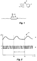
- Fig.1 schematically shows a ship 1 at sea, and a satellite 2 emitting a signal 4.
- the satellite equipment for generating and emitting said signal is generally indicated at 3.
- the construction of the satellite equipment 3 does not form part of the invention, and knowledge of this construction is not necessary for understanding the present invention. Therefore, the satellite 2 and its satellite equipment 3 will not be discussed further. Suffice it to say that the satellite 2 may be a satellite as being used at present, such as the GPS satellites.
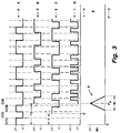
- Fig.2 schematically shows the shape of the navigation signal 5 as emitted by the equipment 3.
- the ordinate is the signal intensity I in arbitrary units
- the abscissa is the time t.
- the navigation signal 5 may have the form of a single pulse, such as is employed in the LORAN-C system (curve A), or the navigation signal 5 may have the form of a sequence of pulses (curve B), such as is employed in the GPS system.
- Fig.2 illustrates that the navigation signal 5 is emitted periodically, the period P being 1 ms in the above-mentioned systems. It is noted that the beginning of each signal period is emitted at moments t0 in time which are very accurately specified under control of a system clock.
- Curve A of fig.3 illustrates the GPS navigation signal 5 at a larger time scale, wherein only a first part of the signal is shown.
- the GPS navigation signal 5 constitutes a pseudo random noise code containing a predetermined number of code bits.
- the code bits are usually referred to as "chips". Each chip can have two possible values, namely +1 or -1. In the GPS system, said predetermined number is 1023. In the following, the individual chips will be referred to as C(1), C(2), ... C(1023).
- Each satellite 2 has its own characteristic code as defined by the set of values of C(1), C(2), ... C(1023).
- the receiver 10 aboard the ship 1 comprises at least one code generator, which can be set to generate a reference signal corresponding to the characteristic code of a specific satellite 2.
- the receiver 10 is equipped with a memory where information on the characteristic codes of a plurality of satellites is stored, so that an operator needs only to indicate which satellite he is interested in and the code generator of the receiver 10 will automatically generate a reference signal corresponding to the characteristic code of that specific satellite of interest (tuning the code generator).
- Figures 3 and 4 illustrate the principle of detecting the propagation time of the signal 4, which will be referred to as delay time ⁇ 0.
- curve A of fig.3 shows the navigation signal 5 as emitted by the satellite 2, i.e. the beginning of C(1) coincides with the beginning t0 of a time period. Therefore, curve A of fig.3 can also be considered a representation of the reference signal as generated by the code generator of the receiver 10.
- Curve B shows the navigation signal 5' as received at an input 11 of the receiver 10 (in the absence of noise and multipath), i.e. the beginning of C(1) being delayed by delay time ⁇ 0 with respect to t0. It is noted that in fig.3 the carrier wave and data are not shown.
- a control device (not shown) associated with the receiver 10 provides a local reference signal 6, which is identical to the reference signal 5 but shifted over a certain shift time ⁇ .
- This local reference signal 6 is shown in curve C of fig.3.
- said control device compares said local reference signal 6 with the navigation signal 5' as received at an input 11 of the receiver 10. More specifically, said control device performs a multiplication operation on the local reference signal 6 and the received navigation signal 5', i.e. the local reference signal 6 is multiplied point by point with the received navigation signal 5'. Subsequently, the resulting signal, which is shown in curve D of fig.3 and which will be referred to as multiplied signal 7, is averaged, i.e. the multiplied signal 7 is integrated over a sufficiently large time to provide a mean value M( ⁇ ) of the multiplied signal 7.
- the multiplied signal 7 can only take the values +1 or -1, depending on whether the values of the signals 6 and 5' are identical to each other or not, respectively. Therefore, the mean value M( ⁇ ) of the multiplied signal 7 will be a value between +1 and -1, too. Since the shape of the multiplied signal 7 depends on the shift time ⁇ , the exact value of M( ⁇ ) depends on the chosen value of the shift time ⁇ . Since the navigation signal 5 is a pseudo random code, said mean value M( ⁇ ) will be practically zero for most values of the shift time ⁇ , and will differ significantly from zero only if the shift time ⁇ approaches the delay time ⁇ 0.
- the exact shape of the correlation function 8 is known in advance, and depends on the specific code of the satellite in question. In curve E of fig.3, this shape is shown as being an ideal triangle.
- the width W of the triangle is a known constant value, for practical purposes equal to twice the duration of a chip; therefore, the correlation function 8 is fully determined by the coordinates ( ⁇ 0, M( ⁇ 0)) of its maximum.
- ⁇ 0 is the relevant parameter determining the position of the correlation function 8 with respect to the beginning of the time periods.
- the correlation function 8 is not an ideal triangle as shown in curve E of fig.3 but is more or less curved, as is shown in fig.10, depending on the characteristics of the receiver.
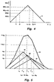
- the conventional method employed in conventional receivers for determining the propagation time ⁇ 0 is explained with reference to fig.4, which shows the correlation function 8 on a larger scale.
- the local reference signal 6 is generated for a first value t1 of the shift time ⁇ , and the corresponding mean value M(t1) of the multiplied signal 7 is calculated.
- the local reference signal 6 is generated for a second value t1+ ⁇ t of the shift time, and the corresponding mean value M(t1+ ⁇ t) of the multiplied signal 7 is calculated.
- the sample spacing, indicated as ⁇ t is a constant value.
- an error signal ⁇ 1 M(t1) - M(t1+ ⁇ t) is calculated.
- DLL Delay Locked Loop
- a serious disadvantage of this conventional method is that the calculated propagation time ⁇ 0 is not accurate enough, which is demonstrated with reference to fig.5, which illustrates the shape of a correlation function 23 which is a combination of a correlation function 24 for the navigation signal 5' as received via the line of sight and two correlation functions 25, 26 for the navigation signal 5' as received via reflection.
- the propagation times ⁇ 1 and ⁇ 2 of the reflection peaks 25, 26 are larger than the propagation time ⁇ 0 of the line of sight peak 24, and their respective maxima A1 and A2 are shown as being smaller than the maximum A0 of the line of sight peak 24.
- the widths W1 and W2 of the reflection peaks 25, 26 are substantially equal to the width W0 of the line of sight peak 24.
- the time ⁇ x calculated by the conventional method is not even an accurate estimate of the position of the maximum of the peak 23, because the peak 23 is not symmetrical in the presence of multipath.
- the present invention is based on mathematical insight in the actual shape of the navigation signal 5' and the correlation function 23 in the presence of multipath. Therefore, according to one aspect of the invention the influence of multipath is eliminated, or at least minimized, by measuring the complete shape of the correlation function 23 of the received navigation signal 5', calculating an estimate of the multipath-induced contribution and the line of sight contribution to said correlation function, and calculating the propagation time ⁇ 0 from the thus calculated line of sight contribution to said correlation function.
- p(t) is a function representing the navigation signal 5, which corresponds to the reference signal as stored in the memory of the receiver 10. It is assumed that there are M ac reflection signals (multipath) contributing to the correlation function 23 of the received navigation signal 5', and that each of said M ac reflection signals can be represented by the function x i (t) ⁇ a i ⁇ p(t- ⁇ i ) ⁇ cos( ⁇ t + ⁇ i ), wherein a i is the amplitude of a signal with index i; ⁇ i is the delay time of the signal with index i; ⁇ i is the phase of the signal with index i; ⁇ is the angular frequency of the carrier signal of the navigation signal.
- the actually received navigation signal 5' as received by the receiver 10 can be written as
- n(t) denotes a noise component.
- the signal x i (t) is also multiplied by a data signal, which can be removed by multiplying the signal with an estimated data signal, as will be evident to a person skilled in the art since such data signal must also be removed in conventional coherent delay lock loop systems. For simplicity of notation, the data signal is left out of formula (1).
- a i , ⁇ i and ⁇ i are unknown variables which are representative for the signal with index i, and which may vary in time.
- the best estimates â i , ⁇ i and ⁇ i of the unknown parameters a i , ⁇ i and ⁇ i are those values which minimize L[s(t)] which is defined as wherein s(t) is defined as It is noted that in practice, where the signals are sampled, the above integral operation can be replaced by a summation over all samples in a certain time interval.
- a criterion equivalent to the above is that all partial derivatives of L(s(t)) are zero. It can be shown that this criterion is fulfilled with wherein max ⁇ ⁇ X ⁇ is defined as that value of ⁇ for which X( ⁇ ) has its global maximum; is the in-phase (real part) and quadrature (imaginary part) downconverted correlation function, corresponding to the combination correlation function 23 discussed in the above example; and R( ⁇ ) is the in-phase (real part) and quadrature (imaginary part) reference correlation function, corresponding to the correlation function 8 discussed in the above example, defined as the correlation function as will occur in practice in the receiver, and normalized such that at the peak the maximum value is one and the phase is zero, such as illustrated in fig.3F.
- the reference correlation function is measured in the absence of noise and multipath, using a signal simulator, and that this shape is stored in a memory of the receiver as the reference correlation function, for instance in the form of a table or a function representing said shape.
- the objective of the invention is attained as soon as the equations (4) are solved, because then the delay time ⁇ 0 of the line of sight signal can be considered calculated accurately by ⁇ 0.
- the equations (4) represent recurrent relations between the optimal parameters ⁇ 0, â0, ⁇ 0, ⁇ 1, â1, ⁇ 1, .... ⁇ Mac , â Mac , ⁇ Mac , for a specific value of M ac .
- equation (3) it will be possible to solve equation (3) directly by using an iterative matrix calculation, this approach costs so much calculating time that a real time implementation is only possible with extremely fast and therefore large and expensive computers systems, if at all.
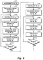
- equations (4) are calculated iteratively, as described as follows with reference to fig.6.
- parameters ⁇ 0, â0, ⁇ 0 are calculated, in a manner to be described later, as optimum values for the largest peak in R0( ⁇ ).
- parameters ⁇ 1, â1, ⁇ 1 are calculated as optimum values for the largest peak in R1( ⁇ ).
- a sixth step 106 new parameters ⁇ 0, â0, ⁇ 0 are calculated as optimum values for the largest peak in the new approximation R0( ⁇ ) as calculated in the fifth step
- the third, fourth, fifth, and sixth steps are then repeated until a suitable stop criterion 201 is fulfilled.
- a suitable stop criterion 201 said steps may be repeated for a predetermined number of times, for instance 10.
- a convergence criterion which has proven to yield good results, is detecting whether the estimated delay ⁇ 0 and/or ⁇ 1 changes less than 0.1 ns between two successive iteration steps.
- parameters ⁇ 2, â2, ⁇ 2 are calculated as optimum values for the largest peak in R2( ⁇ ).
- the ninth, tenth, and eleventh steps are then repeated until a stop criterion 202 is fulfilled, which may be equivalent to the stop criterion 201.
- the contribution of a fourth peak, and new values for the first three peaks can be calculated iteratively; then, the contribution of a fifth peak, and new values for the first four peaks, can be calculated iteratively; etc., as will be clear to a skilled person.
- the contributions of all signals are not calculated simultaneously from the outset, but firstly the contribution of only one signal is calculated, then the contribution of a second signal is added and the contributions of both signals are optimized, then the contribution of a third signal is added and the contributions of all three signals are optimized, etc. It is possible to continue this procedure until the contributions of all M ac +1 signals are calculated.
- M ac of multipath signals actually occurring is not known in advance and is even not necessarily constant.
- the first peak to be calculated is referred to with index 0, whereas previously the index 0 was used to refer to the line of sight peak which, however, does not necessarily correspond to the firstly calculated peak. In the following, the index 0 will again be used to refer to the line of sight peak. It is noted that, after the above-described process is completed, the set of parameters corresponding to the line of sight peak can be recognized easily because this will be the set having the smallest value of ⁇ i .
- Said iteration process may be stopped as soon as it is detected that the error increases, as expressed by the suitable stop criterion of formula (5): SRR(M) ⁇ SRR(M-1) Then, the parameter values obtained for M-1 are chosen as optimum values.
- D is the delay window, i.e. the delay interval which contains the line of sight correlation peak and the peaks of the interfering multipath signals.
- a suitable length for D is twice the duration of a chip, and a suitable position for D is such that the estimated line of sight correlation peak is positioned substantially in the centre of D or within the first half of D, because multipath contributions are only expected at delay values larger than the delay value of the line of sight correlation peak.
- Another alternative stop criterion is expressed by formula (9) SRR(M) ⁇ â0 max(
- M max is chosen as a fixed number equal to one. In that case, approximate parameter values for the two strongest peaks, i.e. the line of sight peak and the strongest reflection peak, are calculated. Only in those cases wherein two or more reflection peaks of almost identical intensity are present will the remaining error be of practical significance, then.
- phase ⁇ is estimated according to formula (12) :
- phase demodulated signal is used to estimate the delay and the amplitude.
- the delay ⁇ of a peak can be estimated in various ways. In the following, two basically different approaches will be discussed.
- the position of the maximum can be calculated using well known analytical methods like the Newton-Raphson method. This method provides an optimal delay estimate with respect to the noise variance, if the sampling interval satifies the Nyquist criterion.
- Fig.7A shows a correlation function, comparable to the correlation function 8 as shown in fig.4.
- the delay of the peak is indicated as ⁇ 0.
- the measured correlation magnitudes R' i (t1) and R' i (t2) are indicated as R1 and R2, respectively.
- f is also a function of ⁇ x .
- a graph is shown of f( ⁇ x ), the vertical axis having arbitrary units. It appears that f is a continuously descending function in a certain area around the maximum, which means that there exists a one-to-one relationship between each value of ⁇ x and each value of f.
- the shape of the function f( ⁇ ) depends on the shape of the correlation function, the characteristics of the receiver, and the magnitude of ⁇ .
- the shape of the correlation function can be established in advance for each receiver, it is also possible to calculate the function f( ⁇ ) in advance, to calculate the inverse function f ⁇ 1, and to store this inverse function in a memory of the receiver, for instance as a table or a polynomial representation.
- t1 and t1+ ⁇ are chosen as close to the peak as possible, more preferably at opposite sides of the peak, because this will yield the most accurate result.
- f R( ⁇ c + 1 2 ⁇ ) R( ⁇ c - 1 2 ⁇ )
- or N
- such a third order difference method offers the advantage of being less susceptible to multipath, because the differencing operations act like a deconvolution, decreasing the pulse width and causing overlapping pulses to become more separated.
- inaccuracies in the receiver, especially in the local reference signal will affect the accuracy of the achieved results more seriously.
- R' i ( ⁇ ) [Re(R i ( ⁇ ))]2 + [Im(R i ( ⁇ ))]2
- R' i ( ⁇ ) [Re(R i ( ⁇ ))]2 + [Im(R i ( ⁇ ))]2
- the fastest way of estimating the amplitude â of the largest peak in a signal is by simply chosing the largest sample value as being the estimate of the amplitude.
- the resulting error can be made acceptably small, for instance by chosing ⁇ arbitrarily small. It is also possible to use the delay ⁇ as calculated above to control the sampling means, such that sampling of the peak occurs exactly at (or very close to) the calculated top of the peak.
- a standard GPS antenna was placed in an arbitrary position at the foot of a large building, and the GPS navigation signal was received during some time. This signal was processed in two receivers simultaneously, the first receiver being a standard GPS receiver operating according to the principle as discussed with reference to fig.4, whereas the other receiver was set up to operate in accordance with the principles of the present invention.
- M max was chosen to be equal to 1 (one). The iterations were stopped when ⁇ 0 changed less than 0.1 ns between two successive iteration steps, or after 10 iteration steps, whichever occurred earlier. The number of (complex) samples was 20. The distance between the samples one-twentieth of the duration of a chip for the first ten samples, and one-tenth of the duration of a chip for the following ten samples. Formula (14) was used for f. The integration time was 1 s.
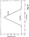
- the calculated values were used as reference values and set at zero; the values plotted in fig.8 for t>0 are the values as calculated and subtracted from said reference values.
- the solid line indicates the fluctuations occurring in the standard GPS receiver's calculations. Due to multipath, the calculated distance measure fluctuates between extreme values which are about 60 m apart, with a standard deviation of the calculated distance measure of more than 10 m.
- the broken line indicates the fluctuations occurring in the second receiver set up to operate in accordance with the principles of the present invention. Although, probably due to noise, the calculated distance measure still fluctuates, the extreme values are only about 5 m apart, while the standard deviation of the errors is reduced to 1.1 m, i.e. an improvement by a factor of 10.
- a receiver 10 comprises an input (antenna) 11 for receiving the navigation signal 4.
- the signal 4 as received is led to an input 31 of the processing device 30, which input 31 is coupled to a first input 35 of a multiplier 34.
- the signal 4 as received may be amplified and/or downconverted to a predetermined intermediate frequency, and then digitized, before being led to the first input 35 of the multiplier 34, as will be clear to a person skilled in the art; for the sake of simplicity, the amplifying means, downconverting means and digitizing means are not shown in fig.9.
- the processing device 30 comprises a generator 32 for generating a signal with frequency ⁇ .
- An output 33 of the generator 32 is coupled to a second input 36 of the multiplier 34.
- the signal 4 as received is demodulated, and the demodulated received navigation signal 5' is provided at an output 37 of the multiplier 34.
- the signal to be processed is to be treated as a complex signal, for which reason the generator 32 in fact has at least two outputs, one providing a signal which can be referred to as cos( ⁇ t), and the other providing a signal which has a phase difference of ⁇ /2 with respect to the first signal and which can be referred to as sin( ⁇ t).
- the cos( ⁇ t) signal is used to process the real (in phase) part of the received signal, whereas the sin( ⁇ t) signal is used to process the imaginary (quadrature) part of the received signal.
- Both processing operations are in principle identical. Therefore, for the sake of simplicity, in fig.9 only one output 33 of the generator 32 is illustrated, and the combination of said output signals will in the following be referred to as exp(j ⁇ t), as will be clear to a skilled person.
- the processing device 30 comprises a plurality of N multipliers 401, 402, 403, across 40 N , referred to in the following as the multipliers 40 k , k being an integer in the interval from 1 to N, wherein N corresponds to the number of samples to be taken from the received navigation signal 5'.
- Each multiplier 40 k has a first input 41 k , a second input 42 k , and an output 43 k .
- Each first input 41 k of the multipliers 40 k is coupled to the output 37 of the multiplier 34 to receive the demodulated received navigation signal 5' r(t) ⁇ exp(j ⁇ t).
- the processing device 30 comprises a plurality of N integrator means 45 k .
- Each integrator means 45 k has an input 46k coupled to the output 43 k of an associated multiplier 40 k , and an output 47 k coupled to an input 51 k of a digital signal processor 50, which may be a computer, as will be clear to a person skilled in the art.
- the integrator means 45 k are arranged for summation of the samples received at their inputs 46k during a predetermined period T, delivering the result of this summation operation at their outputs 47 k , and then restarting a new summation operation from zero.
- the digital signal processor 50 has a clock input 52 coupled to an output 53 of an accurate clock means 54. Further, the digital signal processor 50 has a control output 55 for controllably driving a local reference signal generator 60, which has an output 63 for providing the local reference signal 6.
- the local reference signal generator 60 has a reference input 61 coupled to a memory 62, in which information relating to the characteristic code of the navigation signal 5 is stored, as described above. Although this is not shown in fig.9, the memory 62 may contain information relating to a plurality of characteristic codes of different satellites, while the local reference signal generator 60 may selectably receive information of only one of said codes, such as to selectably tune to the navigation signal of a predetermined satellite, as will be clear to a person skilled in the art.
- the processing device 30 comprises a plurality of N-1 delay means 701, 702, 703, across 70 N-1 , referred to in the following as the delay means 70 n , n being an integer in the interval from 1 to N-1.
- Each delay means 70 n has an input 71 n and an output 72 n , and is arranged to provide at its output 72 n a copy of a signal received at its input 71 n yet delayed over a delay time D ⁇ n .
- all delay means 70 n provide the same delay time D ⁇ .
- the delay means are coupled in series, such that the input 71 n of a delay means 70 n is coupled to the output 72 n-1 of a previous delay means 70 n-1 .
- the input 711 of the first delay means 701 is coupled to the output 63 of the local reference signal generator 60, which is also coupled to the second input 421 of the first multiplier 401.
- the output 72 n of each delay means 70 n is coupled to the second input 42 n+1 of an associated multiplier 40 n+1 .
- each multiplier 40 k provides a multiplied signal 7 which can be expressed as r(t) ⁇ exp(j ⁇ t) ⁇ p(t- ⁇ k ).
- Said samples are "refreshed" after each integration period T, and read by the digital signal processor 50 at its inputs 51 k .
- the digital signal processor 50 is programmed to calculate the sets of equations (4), preferably using the iteration steps as described with reference to fig.6, in which said samples read at its inputs 51 k are utilized.
- the integration period T is chosen not to exceed 10 ms in order to get proper data estimates. However, this does not mean that it is absolutely necessary that the digital signal processor 50 calculates the entire sets of equations (4) once every 10 ms; where only ionospheric changes play a role of importance, it suffices to calculate the sets of equations (4) once every second or even less often.
- the phase of the carrier wave once every 10 ms in a conventional way. From this estimated phase, the data and the frequency deviation of the local generator can be determined. The frequency deviation thus determined is used for controlling the frequency of the signal generator and the code generator, such that their frequency error remains substantially zero.
- the calculated data which is present in the form of phase jumps, is used to remove the data from the correlation samples by multiplying the correlation samples with the estimated data bits, after which the thus multiplied correlation samples can be averaged over 1 sec or more. In order to obtain precise estimates of the phase and the delay, it then suffices to calculate the sets of equations (4) once every second or even less often.
- the digital signal processor 50 controls the generator 32 and the local reference signal generator 60, which comprise preferably a numerically controlled oscillator. More specifically, the generator 32 is controlled such that ⁇ 0 is approximately zero. By amending the bias shift ⁇ b , the local reference signal generator 60 is controlled in such a way that the peak is kept within the delay window D. Alternatively, it is possible to control the local reference signal generator 60 in such a way that the phase of the maximum of the correlation function of the received signal is zero. For more information, reference is made to Spilker, who describes a tracking loop and delay lock loop which are designed for assuring that one of the samples substantially coincides with the top of the estimated line of sight peak, while two other samples are situated symetrically around said peak.
- Spilker who describes a tracking loop and delay lock loop which are designed for assuring that one of the samples substantially coincides with the top of the estimated line of sight peak, while two other samples are situated symetrically around said peak.
- the digital signal processor 50 further has a data output 59 for feeding the calculated estimates to a suitable display means such as a plotter, a printer or a CRT, and/or to a suitable storage means such as a computer memory, as is well known in the art.
- a suitable display means such as a plotter, a printer or a CRT
- a suitable storage means such as a computer memory
Abstract
A method and device for processing a signal are described, wherein an estimate of a multipath-induced contribution to a demodulated navigation signal is calculated and subtracted from said demodulated navigation signal to obtain an estimated line of sight contribution to said demodulated navigation signal, and a propagation time τ₀ is calculated from the thus calculated line of sight contribution to said demodulated navigation signal, such that a very accurate propagation time τ₀ of said navigation signal can be calculated.
Description
- The present invention relates to a method and device for processing a signal, for use in communication systems or satellite navigation systems, for instance. More particularly, the present invention relates to a method and device for processing a signal wherein any errors caused by multipath are eliminated or at least reduced. In one particular embodiment, the present invention relates to a navigation system.
- In principle, communication from a transmitter to a receiver involves the transmission, by the transmitter, of a carrier wave signal which is coded by an information signal, such as by AM or FM, and the reception, by the receiver, of the coded signal. In the receiver, the received signal is decoded for obtaining the information therein. The propagation time of the signal, i.e. the time which passes between the moment of transmission and the moment of reception, depends upon the distance between the transmitter and the receiver, and upon the propagation speed of the carrier wave signal, as is well known.
- In practice, the carrier wave signal reaches the receiver not only directly, i.e. via the line of sight, but also via one or more reflections from objects such as buildings, mountains, clouds, atmospheric layers, etc. Since the propagation path via reflection is always longer than the line of sight, the propagation time of the signal via reflection is always longer than the propagation time of the signal via the line of sight, i.e. a reflected signal always has a certain delay with respect to the direct signal. The receiver can not distinguish between the direct signal and a reflected signal, and the combination of the direct signal as received by the receiver and the reflected signals as received by the receiver is processed as if it were an undistorted signal; however, said combination obviously contains an error with respect to the signal as transmitted. This problem is commonly known as "multipath". Multipath can also be caused by diffraction.
- Communication of the above-described kind is commonly used for many applications, and in most applications it is a general desire to reduce the errors caused by multipath. However, one application where reducing such errors is extremely important is navigation, such as satellite navigation, and the present invention will be described with reference to a navigation system, although it is explicitly noted that the invention is not restricted to such use.
- In the context of the present application, navigation is based on the principle of determining the distance between an object and a reference position by means of a communication signal. A reference station, such as a satellite, emits a signal, which is received by a receiver associated with said object. By measuring the propagation time of the signal, the distance of the object to the reference station can be calculated. Similarly, the distances of the object to a second and possibly further reference stations are calculated. In the case of a stationary reference station, the position of the reference station is constant and may be incorporated in the receiver as a constant value. In the case of a non-stationary reference station such as a satellite, the signal may contain information regarding the position of the reference station. Since, therefore, the positions of the reference stations are "known" by the receiver, it is thus possible to calculate the exact position of the object.
- Examples of such navigation systems of the above-described type are known under the names GPS and LORAN-C. These systems are used, for instance, by ships at sea, and by aeroplanes in their approaching an airport. For a more detailed description of such systems, reference is made to the following publications:
J.J. Spilker: "Digital Communications by Satellite", Prentice Hall, New Jersey, 1977;
N. Ackroyd and R. Lorimer: "Global Navigation: A GPS User's Guide", Lloyd's of London Press, London, 1990;
B. Forsell: "Radio Navigation Systems", Prentice Hall, 1991, ISBN 0-13-751058-6. - It will be evident that in the above-mentioned applications, accuracy is of utmost importance, and any error due to multipath should be eliminated or at least minimized.
- It is, therefore, a general objective of the present invention to eliminate multipath-induced errors.
- This and other objects are achieved in accordance with the present invention by producing a method and a device for processing a received signal, said method and device having the capability of detecting the presence of multipath and the capability of determining the contribution of the line of sight signal and the contribution of the multipath signals. The inventive method and device then removes the contribution of the multipath signals from the received signal, thus leaving an uncorrupted line of sight signal. As such, using the uncorrupted line of sight signal, an accurate propagation time from a signal source to the receiver can be determined.
- The invention will be explained in more detail by discussing a preferred embodiment with reference to the drawing, wherein:
- fig.1
- schematically shows a situation for employing the present invention;
- fig.2
- schematically shows the shape of an undistorted navigation signal;
- fig.3
- illustrates a correlation operation;
- fig.4
- schematically shows the idealized shape of a correlation function, and illustrates the conventional method of processing the navigation signal;
- fig.5
- schematically shows a combination of three correlation function peaks of a multipath signal, and illustrates the drawbacks of the conventional method;
- fig.6
- illustrates the steps taken by a preferred method of the invention;
- fig.7A
- schematically shows the idealized shape of a correlation function, and illustrates the inventive method of processing the navigation signal;
- fig.7B
- schematically shows the shape of an auxiliary function;
- fig.8
- illustrates the effect of the invention;
- fig.9
- illustrates an example of a device according to the invention; and
- fig.10
- illustrates the shape of a correlation function in practice.
- Fig.1 schematically shows a
ship 1 at sea, and asatellite 2 emitting asignal 4. The satellite equipment for generating and emitting said signal is generally indicated at 3. The construction of thesatellite equipment 3 does not form part of the invention, and knowledge of this construction is not necessary for understanding the present invention. Therefore, thesatellite 2 and itssatellite equipment 3 will not be discussed further. Suffice it to say that thesatellite 2 may be a satellite as being used at present, such as the GPS satellites. - For the purpose of the present discussion it will be neglected that the
signal 4 contains data carrying an information message, and only anavigation signal 5 modulated on the carrier wave of thesignal 4 is considered. Fig.2 schematically shows the shape of thenavigation signal 5 as emitted by theequipment 3. In fig.2, the ordinate is the signal intensity I in arbitrary units, and the abscissa is the time t. Thenavigation signal 5 may have the form of a single pulse, such as is employed in the LORAN-C system (curve A), or thenavigation signal 5 may have the form of a sequence of pulses (curve B), such as is employed in the GPS system. Fig.2 illustrates that thenavigation signal 5 is emitted periodically, the period P being 1 ms in the above-mentioned systems. It is noted that the beginning of each signal period is emitted at moments t₀ in time which are very accurately specified under control of a system clock. - Curve A of fig.3 illustrates the
GPS navigation signal 5 at a larger time scale, wherein only a first part of the signal is shown. TheGPS navigation signal 5 constitutes a pseudo random noise code containing a predetermined number of code bits. In order to distinguish the code bits from data bits, the code bits are usually referred to as "chips". Each chip can have two possible values, namely +1 or -1. In the GPS system, said predetermined number is 1023. In the following, the individual chips will be referred to as C(1), C(2), ... C(1023). Eachsatellite 2 has its own characteristic code as defined by the set of values of C(1), C(2), ... C(1023). - The
receiver 10 aboard theship 1 comprises at least one code generator, which can be set to generate a reference signal corresponding to the characteristic code of aspecific satellite 2. In general, thereceiver 10 is equipped with a memory where information on the characteristic codes of a plurality of satellites is stored, so that an operator needs only to indicate which satellite he is interested in and the code generator of thereceiver 10 will automatically generate a reference signal corresponding to the characteristic code of that specific satellite of interest (tuning the code generator). - Figures 3 and 4 illustrate the principle of detecting the propagation time of the
signal 4, which will be referred to as delay time τ₀. As mentioned above, curve A of fig.3 shows thenavigation signal 5 as emitted by thesatellite 2, i.e. the beginning of C(1) coincides with the beginning t₀ of a time period. Therefore, curve A of fig.3 can also be considered a representation of the reference signal as generated by the code generator of thereceiver 10. Curve B shows the navigation signal 5' as received at aninput 11 of the receiver 10 (in the absence of noise and multipath), i.e. the beginning of C(1) being delayed by delay time τ₀ with respect to t₀. It is noted that in fig.3 the carrier wave and data are not shown. - In order to determine the time delay τ₀, a control device (not shown) associated with the
receiver 10 provides alocal reference signal 6, which is identical to thereference signal 5 but shifted over a certain shift time τ. Thislocal reference signal 6 is shown in curve C of fig.3. - In order to determine whether the (known) shift time τ equals the (unknown) time delay τ₀, said control device compares said
local reference signal 6 with the navigation signal 5' as received at aninput 11 of thereceiver 10. More specifically, said control device performs a multiplication operation on thelocal reference signal 6 and the received navigation signal 5', i.e. thelocal reference signal 6 is multiplied point by point with the received navigation signal 5'. Subsequently, the resulting signal, which is shown in curve D of fig.3 and which will be referred to as multipliedsignal 7, is averaged, i.e. the multipliedsignal 7 is integrated over a sufficiently large time to provide a mean value M(τ) of the multipliedsignal 7. - The multiplied
signal 7 can only take the values +1 or -1, depending on whether the values of thesignals 6 and 5' are identical to each other or not, respectively. Therefore, the mean value M(τ) of the multipliedsignal 7 will be a value between +1 and -1, too. Since the shape of the multipliedsignal 7 depends on the shift time τ, the exact value of M(τ) depends on the chosen value of the shift time τ. Since thenavigation signal 5 is a pseudo random code, said mean value M(τ) will be practically zero for most values of the shift time τ, and will differ significantly from zero only if the shift time τ approaches the delay time τ₀. In an ideal case, if the shift time τ equals the delay time τ₀, said mean value M(τ) will be equal to 1 (one). Curve E of fig.3 illustrates this characteristic of said mean value M(τ) as a function of the shift time τ, this function being referred to ascorrelation function 8. - The exact shape of the
correlation function 8 is known in advance, and depends on the specific code of the satellite in question. In curve E of fig.3, this shape is shown as being an ideal triangle. The width W of the triangle is a known constant value, for practical purposes equal to twice the duration of a chip; therefore, thecorrelation function 8 is fully determined by the coordinates (τ₀, M(τ₀)) of its maximum. Herein τ₀ is the relevant parameter determining the position of thecorrelation function 8 with respect to the beginning of the time periods. - It is noted that in practice the
correlation function 8 is not an ideal triangle as shown in curve E of fig.3 but is more or less curved, as is shown in fig.10, depending on the characteristics of the receiver. - Further it is noted that in systems such as LORAN-C, wherein in each time period only one navigation signal pulse having a predetermined shape is emitted instead of a pseudo random code, the navigation signal pulse itself can be substituted for the
correlation function 8 as discussed above. - In the following, the conventional method employed in conventional receivers for determining the propagation time τ₀ is explained with reference to fig.4, which shows the
correlation function 8 on a larger scale. Firstly, thelocal reference signal 6 is generated for a first value t₁ of the shift time τ, and the corresponding mean value M(t₁) of the multipliedsignal 7 is calculated. Secondly, thelocal reference signal 6 is generated for a second value t₁+Δt of the shift time, and the corresponding mean value M(t₁+Δt) of the multipliedsignal 7 is calculated. Herein, the sample spacing, indicated as Δt, is a constant value. - From the respective values M(t₁) and M(t₁+Δt) an error signal ε₁ = M(t₁) - M(t₁+Δt) is calculated. This error signal is used to control the shift time of the
local reference signal 6, such that when the mean value M(τ) is subsequently calculated for two values t₂ and t₂+Δt, the error signal ε₂ = M(t₂) - M(t₂+Δt) is less than εl. This procedure, which is known as Delay Locked Loop (DLL), is executed continuously so that in practice at any particular moment ε ≈ 0, and, based on the assumption that the peak of thecorrelation function 8 is symmetrical, the propagation time τ₀ can be calculated according to the formula
- A serious disadvantage of this conventional method is that the calculated propagation time τ₀ is not accurate enough, which is demonstrated with reference to fig.5, which illustrates the shape of a
correlation function 23 which is a combination of acorrelation function 24 for the navigation signal 5' as received via the line of sight and twocorrelation functions sight peak 24, and their respective maxima A1 and A2 are shown as being smaller than the maximum A0 of the line ofsight peak 24. The widths W1 and W2 of the reflection peaks 25, 26 are substantially equal to the width W0 of the line ofsight peak 24. - In the conventional method, the
correlation function 23 is treated as if no multipath is present, i.e. thecorrelation function 23 is processed based on the assumption that it is an undistorted correlation function. Then, the conventional method may, for instance, result in I(tx) and I(tx+Δtx) satisfying the stop criterion for the error signal ε, and the propagation time τx is calculated as
sight peak 24. - In fact, the time τx calculated by the conventional method is not even an accurate estimate of the position of the maximum of the
peak 23, because thepeak 23 is not symmetrical in the presence of multipath. The conventional method can only be improved in this respect by decreasing Δt, in order to sample the peak 23 at higher positions on the peak. This may, for instance, result in I(ty) and I(ty+Δty) satisfying the stop criterion for the error signal ε, and the propagation time τy is calculated as
- In fact, even if the conventional method were modified such that the highest point of the peak 23 were calculated accurately, it is inherently impossible for the conventional method to yield the correct value of τ₀ in situations as illustrated in fig.5 because, as can clearly be seen in fig.5, the maximum of the
combination peak 23 is shifted with respect to the maximum of the line ofsight peak 24. - It is noted that in fig.5 the peaks are shown in their ideal form, i.e. with sharp tips. However, as noted above, in practice the tips will be curved, which will cause a further increase in the deviation of the calculated value of the propagation time with respect to τ₀.
- The present invention is based on mathematical insight in the actual shape of the navigation signal 5' and the
correlation function 23 in the presence of multipath. Therefore, according to one aspect of the invention the influence of multipath is eliminated, or at least minimized, by measuring the complete shape of thecorrelation function 23 of the received navigation signal 5', calculating an estimate of the multipath-induced contribution and the line of sight contribution to said correlation function, and calculating the propagation time τ₀ from the thus calculated line of sight contribution to said correlation function. - This will be explained in the following discussion, wherein p(t) is a function representing the
navigation signal 5, which corresponds to the reference signal as stored in the memory of thereceiver 10. It is assumed that there are Mac reflection signals (multipath) contributing to thecorrelation function 23 of the received navigation signal 5', and that each of said Mac reflection signals can be represented by the function xi(t) ≡ ai · p(t-τi) · cos(ωt + ϑi), wherein
ai is the amplitude of a signal with index i;
τi is the delay time of the signal with index i;
ϑi is the phase of the signal with index i;
ω is the angular frequency of the carrier signal of the navigation signal. - Then, in the presence of multipath propagation, the actually received navigation signal 5' as received by the
receiver 10 can be written as
Herein, the index i = 0 denotes the line of sight signal, while the index i = 1, 2, ... Mac denotes the multipath signals. Further, n(t) denotes a noise component.
In practice, the signal xi(t) is also multiplied by a data signal, which can be removed by multiplying the signal with an estimated data signal, as will be evident to a person skilled in the art since such data signal must also be removed in conventional coherent delay lock loop systems. For simplicity of notation, the data signal is left out of formula (1). - It is observed that ai, τi and ϑi are unknown variables which are representative for the signal with index i, and which may vary in time. According to maximum likelihood estimation theory, the best estimates âi, τ̂i and ϑ̂i of the unknown parameters ai, τi and ϑi are those values which minimize L[s(t)] which is defined as

wherein s(t) is defined as
It is noted that in practice, where the signals are sampled, the above integral operation can be replaced by a summation over all samples in a certain time interval. - A criterion equivalent to the above is that all partial derivatives of L(s(t)) are zero. It can be shown that this criterion is fulfilled with

wherein

is the in-phase (real part) and quadrature (imaginary part) downconverted correlation function, corresponding to thecombination correlation function 23 discussed in the above example; and R(τ) is the in-phase (real part) and quadrature (imaginary part) reference correlation function, corresponding to thecorrelation function 8 discussed in the above example, defined as the correlation function as will occur in practice in the receiver, and normalized such that at the peak the maximum value is one and the phase is zero, such as illustrated in fig.3F. According to the invention it is preferred that the reference correlation function is measured in the absence of noise and multipath, using a signal simulator, and that this shape is stored in a memory of the receiver as the reference correlation function, for instance in the form of a table or a function representing said shape. - It will be clear that the objective of the invention is attained as soon as the equations (4) are solved, because then the delay time τ₀ of the line of sight signal can be considered calculated accurately by τ̂₀. However, the equations (4) represent recurrent relations between the optimal parameters τ̂₀, â₀, ϑ̂₀, τ̂₁, â₁, ϑ̂₁, .... τ̂Mac, âMac, ϑ̂Mac, for a specific value of Mac. Although in theory it will be possible to solve equation (3) directly by using an iterative matrix calculation, this approach costs so much calculating time that a real time implementation is only possible with extremely fast and therefore large and expensive computers systems, if at all.
- In a more practical procedure according to the invention, the equations (4) are calculated iteratively, as described as follows with reference to fig.6.
- In a
first step 101, a first peak correlation function R₀(τ) is approximated as being equal to Rx(τ), according to the formula R₀(τ) = Rx(τ). - In a
second step 102, parameters τ̂₀, â₀, ϑ̂₀ are calculated, in a manner to be described later, as optimum values for the largest peak in R₀(τ). - In a
third step 103, the contribution of said calculated parameters τ̂₀, â₀, ϑ̂₀ is subtracted from Rx(τ) to yield a second peak correlation function R₁(τ), according to the formula R₁(τ) = Rx(τ) - â₀ · R(τ- τ̂₀) · exp(jϑ̂₀). - In a
fourth step 104, parameters τ̂₁, â₁, ϑ̂₁ are calculated as optimum values for the largest peak in R₁(τ). - In a
fifth step 105, the contribution of said calculated parameters τ̂₁, â₁, ϑ̂₁ is subtracted from Rx(τ) to yield a new approximation of the first peak correlation function R₀(τ) according to the formula R₀(τ) = Rx(τ) - â₁ · R(τ-τ̂₁) · exp(jϑ̂₁) - In a
sixth step 106, new parameters τ̂₀, â₀, ϑ̂₀ are calculated as optimum values for the largest peak in the new approximation R₀(τ) as calculated in the fifth step - The third, fourth, fifth, and sixth steps are then repeated until a
suitable stop criterion 201 is fulfilled. As an example for such asuitable stop criterion 201, said steps may be repeated for a predetermined number of times, forinstance 10. However, it is also possible to repeat said steps until the parameters τ̂₀, â₀, ϑ̂₀ and τ̂₁, â₁, ϑ̂₁ have converged according to predetermined convergence criteria, as will be clear to a person skilled in the art. A convergence criterion which has proven to yield good results, is detecting whether the estimated delay τ̂₀ and/or τ̂₁ changes less than 0.1 ns between two successive iteration steps. - At this point, for two signals the estimated contributions x̂₀(t) and x̂₁(t) to the received navigation signal 5' are provided as x̂₀(t) = â₀ · p(t-τ̂₀) · cos(ωt + ϑ̂₀) and x̂₁(t) = â₁ · p(t-τ̂₁) · cos (ωt + ϑ̂₁), and the estimated contributions R₀(τ) and R₁(τ) to the in-phase/quadrature downconverted correlation function Rx(τ) are provided as R₀(τ) = â₀ · R(τ-τ̂₀) · exp(jϑ̂₀) and R₁(τ) = â₁ · R(τ-τ̂₁) · exp(jϑ̂₁).
- In case an estimated contribution for a third signal is to be calculated, the contribution of said calculated parameters τ̂₀, â₀, ϑ̂₀ and τ̂₁, â₁, ϑ̂₁ is, in a
seventh step 107, subtracted from Rx(τ) to yield a third peak correlation function R₂(τ), according to the formula R₂(τ) = Rx(τ) - â₀ · R(τ-τ̂₀) · exp(jϑ̂₀) - â₁ · R(τ-τ̂₁) · exp(jϑ̂₁). - In an
eighth step 108, parameters τ̂₂, â₂, ϑ̂₂ are calculated as optimum values for the largest peak in R₂(τ). - In a
ninth step 109, new parameters τ̂₀, â₀, ϑ̂₀ are calculated as optimum values for the largest peak in R₀(τ) = Rx(τ) - âi · R(τ-τ̂₁) · exp(jϑ̂₁) - â₂ · R(τ-τ̂₂) · exp(jϑ̂₂). - In a
tenth step 110, new parameters τ̂₁, â₁, ϑ̂₁ are calculated as optimum values for the largest peak in R₁(τ) = Rx(τ) - â₀ · R(τ-τ̂₀) · exp(jϑ̂₀) - â₂ · R(τ-τ̂₂) · exp(jϑ̂₂), using the parameters τ̂₀, â₀, ϑ̂₀ as calculated in the ninth step. - In an eleventh step 111, new parameters τ̂₂, â₂, ϑ̂₂ are calculated as optimum values for the largest peak in R₂(τ) = Rx(τ) - â₀ · R(τ-τ̂₀) · exp(jϑ̂₀) - â₁ · R(τ-τ̂₁) · exp(jϑ̂₁), using the parameters τ̂₀, â₀, ϑ̂₀ as calculated in the ninth step and the parameters τ̂₁, â₁, ϑ̂₁ as calculated in the tenth step.
- The ninth, tenth, and eleventh steps are then repeated until a
stop criterion 202 is fulfilled, which may be equivalent to thestop criterion 201. - In an analogous way, the contribution of a fourth peak, and new values for the first three peaks, can be calculated iteratively; then, the contribution of a fifth peak, and new values for the first four peaks, can be calculated iteratively; etc., as will be clear to a skilled person.
- Stated differently, the contributions of all signals are not calculated simultaneously from the outset, but firstly the contribution of only one signal is calculated, then the contribution of a second signal is added and the contributions of both signals are optimized, then the contribution of a third signal is added and the contributions of all three signals are optimized, etc. It is possible to continue this procedure until the contributions of all Mac+1 signals are calculated. However, it is noted that in practice the number Mac of multipath signals actually occurring is not known in advance and is even not necessarily constant. Therefore, after each cycle in the above-described procedure when the contributions of M+1 signals are calculated, wherein M is the considered number of multipath contributions, the multipath error is not eliminated sufficiently if M is less than Mac, whereas an increased noise error is induced if M is larger than Mac. Therefore, in order to eliminate this problem, according to the invention it is preferred to solve the equations (4) successively for M = 0, 1, 2, ..., Mmax, as explained above, and to stop this iteration process as soon as a suitable stop criterion is fulfilled, or when M=Mmax, whichever occurs first, wherein Mmax is a predetermined fixed value serving as an upper limit for the iteration process in order to prevent the calculation time from becoming too large. A suitable value is for instance Mmax = 3 or Mmax = 4.
- It is noted that, in the procedure as described in the above, the first peak to be calculated is referred to with
index 0, whereas previously theindex 0 was used to refer to the line of sight peak which, however, does not necessarily correspond to the firstly calculated peak. In the following, theindex 0 will again be used to refer to the line of sight peak. It is noted that, after the above-described process is completed, the set of parameters corresponding to the line of sight peak can be recognized easily because this will be the set having the smallest value of τ̂i. - Said iteration process may be stopped as soon as it is detected that the error increases, as expressed by the suitable stop criterion of formula (5):

Then, the parameter values obtained for M-1 are chosen as optimum values. - In formula (5), SRR(M) is defined as the Signal-to-Residual-Ratio according to SRR(M) = â₀²/V(M) (6) wherein V(M) is defined as the variance of the residuals after estimation of all parameters according to formula (7):

wherein D is the delay window, i.e. the delay interval which contains the line of sight correlation peak and the peaks of the interfering multipath signals. In practice, a suitable length for D is twice the duration of a chip, and a suitable position for D is such that the estimated line of sight correlation peak is positioned substantially in the centre of D or within the first half of D, because multipath contributions are only expected at delay values larger than the delay value of the line of sight correlation peak. - It is noted that in practice the in-phase/quadrature downconverted correlation function Rx(τ) is sampled, so that the integral operation of formula (7) can be replaced by a summation operation.
- As an alternative stop criterion, it is possible to use formula (8) instead of formula (5)

wherein δ is a suitable treshold value which, for instance, may be chosen equal to that specific Signal-to-Noise-Ratio SNR which just leads to an acceptable error. - Another alternative stop criterion is expressed by formula (9)

wherein max(|res|) is defined as the maximum absolute value of the residual function res in the interval D, res being defined as
- In a simple implementation of the present invention, which has proved to yield sufficiently good results in most practical circumstances, Mmax is chosen as a fixed number equal to one. In that case, approximate parameter values for the two strongest peaks, i.e. the line of sight peak and the strongest reflection peak, are calculated. Only in those cases wherein two or more reflection peaks of almost identical intensity are present will the remaining error be of practical significance, then.
- In the following, a description is given of the most preferred procedure for calculating parameters τ̂, â, ϑ̂ as optimum values for the largest peak in a correlation function Ri(τ), such as described with reference to, for instance,
step 102. - Firstly, it is determined which one of the complex samples of said correlation function provides the largest value for [Re(Ri(τ))]² + [Im(Ri(τ))]². The corresponding delay will be referred to as τmax. In other words:

- From said one sample, the phase ϑ̂ is estimated according to formula (12) :

- Once the phase is known, it is used to perform a phase rotation on the input signal in order to obtain a coherently demodulated signal according to formula (13):

- The thus obtained phase demodulated signal is used to estimate the delay and the amplitude.
- The delay τ̂ of a peak can be estimated in various ways. In the following, two basically different approaches will be discussed.
- Firstly, it is possible to use all samples of the peak, and to calculate interpolation values to the samples, in order to obtain a more or less continuous representation of the shape of the peak. Subsequently, the position of the maximum can be calculated using well known analytical methods like the Newton-Raphson method. This method provides an optimal delay estimate with respect to the noise variance, if the sampling interval satifies the Nyquist criterion.
- Secondly, it is possible to use only a small number of samples of the peak. This method is based on the fact that the shape of the peak is known in advance, and is preferred according to the invention because it is much faster than the previously described method. Said number of samples can be as small as two, as will be discussed in the following with reference to fig.7.
- Fig.7A shows a correlation function, comparable to the
correlation function 8 as shown in fig.4. The delay of the peak is indicated as τ₀. Samples A and B of this function are shown, taken at two different delays t₁ and t₂, spaced by the sampling interval Δτ, such that t₂ = t₁ + Δτ. The measured correlation magnitudes R'i(t₁) and R'i(t₂) are indicated as R1 and R2, respectively. - In the following, the delay lying exactly in the middle of t₁ and t₂ will be indicated as τc, such that


- Further, the distance from tc to τ₀ will be indicated as τx, such that


- With said measured correlation magnitudes


- Therefore, f is also a function of τx. In fig.7B a graph is shown of f(τx), the vertical axis having arbitrary units. It appears that f is a continuously descending function in a certain area around the maximum, which means that there exists a one-to-one relationship between each value of τx and each value of f. The shape of the function f(τ) depends on the shape of the correlation function, the characteristics of the receiver, and the magnitude of Δτ. Since, as is mentioned above, the shape of the correlation function can be established in advance for each receiver, it is also possible to calculate the function f(τ) in advance, to calculate the inverse function f⁻¹, and to store this inverse function in a memory of the receiver, for instance as a table or a polynomial representation.
- During operation, two sample values


Then, τ₀ is estimated as
- Preferably, t₁ and t₁+Δτ are chosen as close to the peak as possible, more preferably at opposite sides of the peak, because this will yield the most accurate result.
- As an alternative, one might define f according to

- In another alternative embodiment, four sampled values are used, wherein f can be defined according to:

or
Herein, N is a normalisation parameter, equal to the sum of several absolute measured values. For instance, N = |R(τ₀)| or
- In theory, such a third order difference method offers the advantage of being less susceptible to multipath, because the differencing operations act like a deconvolution, decreasing the pulse width and causing overlapping pulses to become more separated. On the other hand, inaccuracies in the receiver, especially in the local reference signal, will affect the accuracy of the achieved results more seriously.
- As an alternative to formula (13), it is possible to use an incoherently demodulated signal according to, for instance, formula (13a) or (13b):


- The fastest way of estimating the amplitude â of the largest peak in a signal is by simply chosing the largest sample value as being the estimate of the amplitude. The resulting error can be made acceptably small, for instance by chosing Δτ arbitrarily small. It is also possible to use the delay τ̂ as calculated above to control the sampling means, such that sampling of the peak occurs exactly at (or very close to) the calculated top of the peak.
- To estimate the amplitude, it is also possible to use similar techniques as described in the above in relation to the delay. A normalized peak shape function g can be defined as

- Using one measured amplitude sample x and an estimated delay τ̂ as calculated with the above method, the amplitude can be estimated according to:

- As an alternative, it is possible to use the second order derivative of the peak, according to:

and to proceed in a similar way as described in the above with respect to formula (15). - The advantageous effect of the invention will now be illustrated by discussing an example whith reference to fig.8.
- A standard GPS antenna was placed in an arbitrary position at the foot of a large building, and the GPS navigation signal was received during some time. This signal was processed in two receivers simultaneously, the first receiver being a standard GPS receiver operating according to the principle as discussed with reference to fig.4, whereas the other receiver was set up to operate in accordance with the principles of the present invention. Mmax was chosen to be equal to 1 (one). The iterations were stopped when τ̂₀ changed less than 0.1 ns between two successive iteration steps, or after 10 iteration steps, whichever occurred earlier. The number of (complex) samples was 20. The distance between the samples one-twentieth of the duration of a chip for the first ten samples, and one-tenth of the duration of a chip for the following ten samples. Formula (14) was used for f. The integration time was 1 s.
- Fig.8 shows the fluctuations δτ of the delay time τ₀ of the line of sight peak as calculated by both receivers, translated into a distance measure δL according to the formula δL = cδτ, plotted against the time t. At time t=0, the calculated values were used as reference values and set at zero; the values plotted in fig.8 for t>0 are the values as calculated and subtracted from said reference values.
- The solid line indicates the fluctuations occurring in the standard GPS receiver's calculations. Due to multipath, the calculated distance measure fluctuates between extreme values which are about 60 m apart, with a standard deviation of the calculated distance measure of more than 10 m.
- The broken line indicates the fluctuations occurring in the second receiver set up to operate in accordance with the principles of the present invention. Although, probably due to noise, the calculated distance measure still fluctuates, the extreme values are only about 5 m apart, while the standard deviation of the errors is reduced to 1.1 m, i.e. an improvement by a factor of 10.
- In the following, an exemplary embodiment of the
processing device 30 according to the invention will be described in more detail with reference to fig.9. - As described above, a
receiver 10 comprises an input (antenna) 11 for receiving thenavigation signal 4. Thesignal 4 as received is led to an input 31 of theprocessing device 30, which input 31 is coupled to afirst input 35 of amultiplier 34. It is noted that, if desired, thesignal 4 as received may be amplified and/or downconverted to a predetermined intermediate frequency, and then digitized, before being led to thefirst input 35 of themultiplier 34, as will be clear to a person skilled in the art; for the sake of simplicity, the amplifying means, downconverting means and digitizing means are not shown in fig.9. - The
processing device 30 comprises agenerator 32 for generating a signal with frequency ω. Anoutput 33 of thegenerator 32 is coupled to asecond input 36 of themultiplier 34. In themultiplier 34, thesignal 4 as received is demodulated, and the demodulated received navigation signal 5' is provided at anoutput 37 of themultiplier 34. - It is noted that the signal to be processed is to be treated as a complex signal, for which reason the
generator 32 in fact has at least two outputs, one providing a signal which can be referred to as cos(ωt), and the other providing a signal which has a phase difference of π/2 with respect to the first signal and which can be referred to as sin(ωt). The cos(ωt) signal is used to process the real (in phase) part of the received signal, whereas the sin(ωt) signal is used to process the imaginary (quadrature) part of the received signal. Both processing operations are in principle identical. Therefore, for the sake of simplicity, in fig.9 only oneoutput 33 of thegenerator 32 is illustrated, and the combination of said output signals will in the following be referred to as exp(jωt), as will be clear to a skilled person. - The
processing device 30 comprises a plurality ofN multipliers multipliers 40k, k being an integer in the interval from 1 to N, wherein N corresponds to the number of samples to be taken from the received navigation signal 5'. Eachmultiplier 40k has a first input 41k, a second input 42k, and an output 43k. Each first input 41k of themultipliers 40k is coupled to theoutput 37 of themultiplier 34 to receive the demodulated received navigation signal 5' r(t)·exp(jωt). - The
processing device 30 comprises a plurality of N integrator means 45k. Each integrator means 45k has an input 46k coupled to the output 43k of an associatedmultiplier 40k, and an output 47k coupled to an input 51k of adigital signal processor 50, which may be a computer, as will be clear to a person skilled in the art. The integrator means 45k are arranged for summation of the samples received at their inputs 46k during a predetermined period T, delivering the result of this summation operation at their outputs 47k, and then restarting a new summation operation from zero. - The
digital signal processor 50 has aclock input 52 coupled to anoutput 53 of an accurate clock means 54. Further, thedigital signal processor 50 has acontrol output 55 for controllably driving a localreference signal generator 60, which has anoutput 63 for providing thelocal reference signal 6. The localreference signal generator 60 has areference input 61 coupled to amemory 62, in which information relating to the characteristic code of thenavigation signal 5 is stored, as described above. Although this is not shown in fig.9, thememory 62 may contain information relating to a plurality of characteristic codes of different satellites, while the localreference signal generator 60 may selectably receive information of only one of said codes, such as to selectably tune to the navigation signal of a predetermined satellite, as will be clear to a person skilled in the art. - The
processing device 30 comprises a plurality of N-1 delay means 70₁, 70₂, 70₃, ..... 70N-1, referred to in the following as the delay means 70n, n being an integer in the interval from 1 to N-1. Each delay means 70n has an input 71n and an output 72n, and is arranged to provide at its output 72n a copy of a signal received at its input 71n yet delayed over a delay time Dτn. In an embodiment, all delay means 70n provide the same delay time Dτ. The delay means are coupled in series, such that the input 71n of a delay means 70n is coupled to the output 72n-1 of a previous delay means 70n-1. Theinput 71₁ of the first delay means 70₁ is coupled to theoutput 63 of the localreference signal generator 60, which is also coupled to thesecond input 42₁ of thefirst multiplier 40₁. The output 72n of each delay means 70n is coupled to the second input 42n+1 of an associatedmultiplier 40n+1. - The
digital signal processor 50 is programmed to drive the localreference signal generator 60 in accurate synchronization with the time periods as specified by the clock means 54. However, thedigital signal processor 50 may shift the beginning of the first chip C(1) of thelocal reference signal 6 with respect to the beginning t₀ of a time period over a certain bias shift τb, as will be explained later. Then, eachmultiplier 40k receives at its second input 42k alocal reference signal 6 which is shifted with respect to the beginning t₀ of a time period over a shift time τk according to the formula
This shiftedlocal reference signal 6 can be expressed as pk(t) = p(t-τk). - At its output 43k, each
multiplier 40k provides a multipliedsignal 7 which can be expressed as r(t)·exp(jωt)·p(t-τk). - Therefore, each integrator means 45k provides at its output 47k a signal which can be expressed as

and which constitutes a sample at τ = τk of the in-phase/quadrature downconverted correlation function Rx(τ). - Said samples are "refreshed" after each integration period T, and read by the
digital signal processor 50 at its inputs 51k. Thedigital signal processor 50 is programmed to calculate the sets of equations (4), preferably using the iteration steps as described with reference to fig.6, in which said samples read at its inputs 51k are utilized. Preferably, in the case of a GPS system, the integration period T is chosen not to exceed 10 ms in order to get proper data estimates. However, this does not mean that it is absolutely necessary that thedigital signal processor 50 calculates the entire sets of equations (4) once every 10 ms; where only ionospheric changes play a role of importance, it suffices to calculate the sets of equations (4) once every second or even less often. - More particularly, in the case of a GPS system, it is possible to estimate the phase of the carrier wave once every 10 ms in a conventional way. From this estimated phase, the data and the frequency deviation of the local generator can be determined. The frequency deviation thus determined is used for controlling the frequency of the signal generator and the code generator, such that their frequency error remains substantially zero. The calculated data, which is present in the form of phase jumps, is used to remove the data from the correlation samples by multiplying the correlation samples with the estimated data bits, after which the thus multiplied correlation samples can be averaged over 1 sec or more. In order to obtain precise estimates of the phase and the delay, it then suffices to calculate the sets of equations (4) once every second or even less often.
- Based on the calculated phase and delay estimates, the
digital signal processor 50 controls thegenerator 32 and the localreference signal generator 60, which comprise preferably a numerically controlled oscillator. More specifically, thegenerator 32 is controlled such that ϑ̂₀ is approximately zero. By amending the bias shift τb, the localreference signal generator 60 is controlled in such a way that the peak is kept within the delay window D. Alternatively, it is possible to control the localreference signal generator 60 in such a way that the phase of the maximum of the correlation function of the received signal is zero. For more information, reference is made to Spilker, who describes a tracking loop and delay lock loop which are designed for assuring that one of the samples substantially coincides with the top of the estimated line of sight peak, while two other samples are situated symetrically around said peak. - The
digital signal processor 50 further has adata output 59 for feeding the calculated estimates to a suitable display means such as a plotter, a printer or a CRT, and/or to a suitable storage means such as a computer memory, as is well known in the art. In practice, the results are fed into a computer, which also receives the estimated results for several other transmitters in order to be able to calculate the exact position of the receiver. This calculation is identical to the calculation performed in existing receivers. - For completeness sake, it is noted that in reality two
multipliers 34 are present, the first one receiving said signal cos(ωt) and the second one receiving said signal sin(ωt) at their respectivesecond inputs 36, such that theirrespective outputs 37 provide the in-phase navigation signal 5' and the quadrature navigation signal 5', respectively. Further, it is noted that the circuitry of themeans - It will be evident that the described embodiments of the invention may be amended or modified by a person skilled in the art without departing from the scope of the invention or the scope of the claims. For instance, in cases where it suffices to only process the real (in phase) part of the received signal, formula (4) simplifies into formula (4A):

- Further, it is possible to use other suitable functions for the shape parameters f and g as described, as long as the used function for f is a continuously descending or ascending function.
Claims (18)
- In a signal transmission system containing a transmitter and a receiver, a method for processing a signal within said receiver, comprising the following steps:
receiving a signal;
demodulating the received signal;
obtaining samples Rx(τ) of the demodulated received signal at a plurality of times τ;
calculating an estimate of a multipath-induced contribution to said demodulated received signal, subtracting said estimated multipath-induced contribution from said demodulated received signal to obtain an estimated line of sight contribution to said demodulated received signal, and calculating a propagation time τ₀ for said signal propagating between said transmitter and said receiver, said propagation time τ₀ is calculated from the thus calculated line of sight contribution to said demodulated received signal. - In a signal transmission system containing a transmitter and a receiver, a method for processing a signal within said receiver, comprising the following steps:
receiving a signal;
demodulating the received signal;
providing a reference signal;
performing a correlation operation on the received signal with said reference signal in order to obtain a correlation function;
obtaining samples Rx(τ) of the correlation function at a plurality of times τ;
calculating an estimate of a multipath-induced contribution to said correlation function;
subtracting said estimated multipath-induced contribution from said correlation function to obtain an estimated line of sight contribution to said correlation function; and
calculating a propagation time τ₀ for said signal propagating between said transmitter and said receiver, said propagation time τ₀ is calculated from the thus calculated line or sight contribution to said correlation function. - Method according to claim 2, wherein said estimate calculating step further comprises the step of calculating parameters âi, τ̂i and ϑ̂i as follows:


wherein âi, τ̂i and ϑ̂i are estimated values for ai, τi and ϑi, respectively. - Method according to claim 2, wherein said estimate calculating step further comprises the step of calculating parameters âi, τ̂i and ϑ̂i as follows:


wherein âi, τ̂i and ϑ̂i are estimated values for ai, τi and ϑi, respectively. - Method according to claim 3, wherein a reference correlation function is measured in the absence of noise and multipath, using a signal simulator, and wherein the shape of the measured reference correlation function is stored in a memory of the receiver, for instance in the form of a table or a function representing said shape.
- Method according to claim 2, wherein said estimate calculating step further comprises performing the following steps:a) calculating parameters τ̂₀, â₀, ϑ̂₀ as optimum values for the largest peak in Rx(τ);b) subtracting the contribution of said calculated parameters τ̂₀, â₀, ϑ̂₀ from Rx(τ) to yield R₁(τ), according to the formula R₁(τ) = Rx(τ) - â₀·R(τ-τ̂₀)·exp(jϑ̂₀);c) calculating parameters τ̂₁, â₁, ϑ̂₁ as optimum values for the largest peak in R₁(τ);d) subtracting the contribution of said calculated parameters τ̂₁, â₁, ϑ̂₁ from Rx(τ) to yield a new approximation of R₀(τ) according to the formula
 e) calculating new parameters τ̂₀, â₀, ϑ̂₀ as optimum values for the largest peak in the new approximation R₀(τ) as calculated in step (d); andf) repeating the steps (b), (c), (d), (e) until a suitable stop criterion is fulfilled.
 - Method according to claim 6, wherein the steps (b), (c), (d), (e) are repeated for a predetermined number of times.
- Method according to claim 6, wherein the steps (b), (c), (d), (e) are repeated until at least one of the parameters τ̂₀, â₀, ϑ̂₀ and τ̂₁, â₁, ϑ̂₁ have converged according to predetermined convergence criteria.
- Method according to claim 6, wherein, in order to calculate an estimated contribution for a third signal, the following steps are performed:g) subtracting the contribution of the calculated parameters τ̂₀, â₀, ϑ̂₀ and τ̂₁, â₁, ϑ̂₁ from Rx(τ) to yield R₂(τ), according to the formula
 h) calculating parameters τ̂₂, â₂, ϑ̂₂ as optimum values for the largest peak in R₂(τ);i) calculating new parameters τ̂₀, â₀, ϑ̂₀ as optimum values for the largest peak in
 j) calculating new parameters τ̂₁, â₁, ϑ̂₁ as optimum values for the largest peak in
 k) calculating new parameters τ̂₂, â₂, ϑ̂₂ as optimum values for the largest peak in
 l) repeating steps (i), (j), (k), until a stop criterion is fulfilled.
 - Method according to claim 2, wherein a phase ϑ̂ of a peak is estimated from one sample Ri(τmax) of said peak, taken preferably but not necessarily at or close to a top of the peak, according to:


- Method according to claim 2, further comprising the step of calculating a function f(τx) in advance, wherein the inverse function f⁻¹ is calculated and stored in a memory of the receiver.
- Method according to claim 11, wherein the function f(τx) is defined as

- Method according to claim 11, wherein the function f is defined as

- Method according to claim 11, wherein the function f is defined as

- Method according to claim 11, wherein the function f is defined as

- Method according to claim 14, wherein N is equal to the sum of several absolute measured values, for instance,

- Method according to claim 2, wherein said samples Rx(τ) are obtained simultaneously.
- Device for processing a signal, comprising:
a digital signal processor;
a generator for generating a signal having frequency ω, which signal can be expressed as exp(-jωt), the generator being controlled by said digital signal processor;
first multiplier having a first input coupled to receive a navigation signal and a second input coupled to an output of the generator;
a plurality of N second multipliers, each of said second multipliers having a first input coupled to an output of the first multiplier;
a plurality of N integrator means, each having an input coupled to an output of an associated second multiplier, and an output coupled to an input of the digital signal processor;
a local reference signal generator coupled to a control output of the digital signal processor and having at least one output for providing a local reference signal;
a plurality of N-1 delay means, each of said delay means having an input and an output, each output being connected to a second input of an associated second multiplier;
wherein the input of a first one of said plurality of delay means is coupled to the output of the local reference signal generator and to the second input of a first one of said plurality of second multipliers, and wherein the input of another delay means is coupled to the output of a previous delay means.
Applications Claiming Priority (2)
| Application Number | Priority Date | Filing Date | Title |
|---|---|---|---|
| US157476 | 1993-11-24 | ||
| US08/157,476 US5615232A (en) | 1993-11-24 | 1993-11-24 | Method of estimating a line of sight signal propagation time using a reduced-multipath correlation function |
Publications (1)
| Publication Number | Publication Date |
|---|---|
| EP0654677A1 true EP0654677A1 (en) | 1995-05-24 |
Family
ID=22563902
Family Applications (1)
| Application Number | Title | Priority Date | Filing Date |
|---|---|---|---|
| EP94308632A Withdrawn EP0654677A1 (en) | 1993-11-24 | 1994-11-23 | Method and device for processing a signal |
Country Status (5)
| Country | Link |
|---|---|
| US (2) | US5615232A (en) |
| EP (1) | EP0654677A1 (en) |
| JP (1) | JPH0837471A (en) |
| CN (1) | CN1113619A (en) |
| AU (1) | AU7898094A (en) |
Cited By (8)
| Publication number | Priority date | Publication date | Assignee | Title |
|---|---|---|---|---|
| FR2745092A1 (en) * | 1996-02-21 | 1997-08-22 | Aisin Seiki | POSITIONING SYSTEM USING SATELLITES OF A GLOBAL POSITIONING SYSTEM |
| WO1997044682A1 (en) * | 1996-05-20 | 1997-11-27 | Trimble Navigation Limited | Variable suppression of multipath signal effects |
| EP0814573A2 (en) * | 1996-06-21 | 1997-12-29 | Nec Corporation | Path-diversity CDMA reception by detecting lower-peak correlation sequence following removal of higher-peak sequences |
| WO1999035763A1 (en) * | 1998-01-12 | 1999-07-15 | Ericsson Inc. | Method and apparatus for multipath delay estimation in direct sequence spread spectrum communication systems |
| EP1065794A2 (en) * | 1999-06-30 | 2001-01-03 | Nec Corporation | Direct sequence CDMA receiver having a delay profile producer with an interpolation function |
| WO2004098087A2 (en) * | 2003-04-28 | 2004-11-11 | Telefonaktiebolaget Lm Ericsson (Publ) | Methods and receivers that estimate multi-path delays by removing signal rays from a power-delay profile |
| WO2005031384A1 (en) * | 2003-09-27 | 2005-04-07 | Koninklijke Philips Electronics N.V. | Method of position determination |
| CN102033219A (en) * | 2009-09-29 | 2011-04-27 | 晨星软件研发(深圳)有限公司 | Frequency tracking method and device for positioning system |
Families Citing this family (62)
| Publication number | Priority date | Publication date | Assignee | Title |
|---|---|---|---|---|
| US7929498B2 (en) | 1995-06-30 | 2011-04-19 | Interdigital Technology Corporation | Adaptive forward power control and adaptive reverse power control for spread-spectrum communications |
| US7020111B2 (en) | 1996-06-27 | 2006-03-28 | Interdigital Technology Corporation | System for using rapid acquisition spreading codes for spread-spectrum communications |
| US6788662B2 (en) | 1995-06-30 | 2004-09-07 | Interdigital Technology Corporation | Method for adaptive reverse power control for spread-spectrum communications |
| US6885652B1 (en) | 1995-06-30 | 2005-04-26 | Interdigital Technology Corporation | Code division multiple access (CDMA) communication system |
| ZA965340B (en) | 1995-06-30 | 1997-01-27 | Interdigital Tech Corp | Code division multiple access (cdma) communication system |
| US6816473B2 (en) | 1995-06-30 | 2004-11-09 | Interdigital Technology Corporation | Method for adaptive forward power control for spread-spectrum communications |
| US6831905B1 (en) | 1995-06-30 | 2004-12-14 | Interdigital Technology Corporation | Spread spectrum system assigning information signals to message-code signals |
| FR2742612B1 (en) * | 1995-12-15 | 1998-02-06 | Sextant Avionique | METHOD AND CIRCUIT FOR RECEIVING POSITIONING SIGNALS BY SATELLITES WITH ELIMINATION OF MULTI-PATH ERRORS |
| GB2309868A (en) * | 1996-01-30 | 1997-08-06 | Sony Corp | Radio receiver detects FCCH synchronising signal |
| US5917866A (en) * | 1997-04-04 | 1999-06-29 | Trimble Navigation Limited | Code multipath estimation for weighted or modified tracking using weighted or modified correlations |
| US5883595A (en) * | 1997-09-15 | 1999-03-16 | Rockwell International Corporation | Method and apparatus for mitigating multipath effects and smoothing groundtracks in a GPS receiver |
| US6259894B1 (en) * | 1997-12-04 | 2001-07-10 | Lucent Technologies Inc. | Method for improved line-of-sight signal detection using RF model parameters |
| US6414634B1 (en) | 1997-12-04 | 2002-07-02 | Lucent Technologies Inc. | Detecting the geographical location of wireless units |
| US6175811B1 (en) | 1997-12-04 | 2001-01-16 | Lucent Technologies Inc. | Method for frequency environment modeling and characterization |
| US6272350B1 (en) | 1997-12-04 | 2001-08-07 | Lucent Technologies Inc. | Method for improved line of sight signal detection using time/frequency analysis |
| US6167351A (en) * | 1998-03-24 | 2000-12-26 | Tektronix, Inc. | Period determination of a periodic signal |
| US5995044A (en) * | 1998-05-01 | 1999-11-30 | Novatel, Inc. | Method and apparatus for characterizing multipath interference in circularly polarized signals |
| US6313786B1 (en) * | 1998-07-02 | 2001-11-06 | Snaptrack, Inc. | Method and apparatus for measurement processing of satellite positioning system (SPS) signals |
| FR2801449A1 (en) * | 1999-11-19 | 2001-05-25 | Thomson Csf | RECEIVER FOR STELLITE POSITIONING SYSTEM IN THE PRESENCE OF INTERFERRED RADIO WAVES PATHS |
| FI112893B (en) | 1999-12-21 | 2004-01-30 | Nokia Corp | Method in receiver and receiver |
| US6541950B2 (en) * | 2000-01-26 | 2003-04-01 | Novatel, Inc. | Multipath meter |
| JP3673700B2 (en) * | 2000-06-27 | 2005-07-20 | 株式会社日立製作所 | Ranging and position measuring method using spread spectrum signal and apparatus for performing the method |
| US6728324B1 (en) * | 2000-07-31 | 2004-04-27 | Rf Micro Devices, Inc. | Method and apparatus for multipath signal compensation in spread-spectrum communications systems |
| US6700929B1 (en) * | 2000-07-31 | 2004-03-02 | Rf Micro Devices, Inc. | Method and apparatus for multipath parameter estimation in spread-spectrum communications systems |
| US6647077B1 (en) | 2000-07-31 | 2003-11-11 | Rf Micro Devices, Inc. | Multipath parameter estimation in spread-spectrum communications systems |
| JP3428637B2 (en) * | 2000-11-27 | 2003-07-22 | 日本電気株式会社 | Multipath detection method and circuit for CDMA receiver |
| US7190712B2 (en) | 2001-05-18 | 2007-03-13 | Global Locate, Inc | Method and apparatus for performing signal correlation |
| US7567636B2 (en) * | 2001-05-18 | 2009-07-28 | Global Locate, Inc. | Method and apparatus for performing signal correlation using historical correlation data |
| US7006556B2 (en) * | 2001-05-18 | 2006-02-28 | Global Locate, Inc. | Method and apparatus for performing signal correlation at multiple resolutions to mitigate multipath interference |
| US7995682B2 (en) * | 2001-05-18 | 2011-08-09 | Broadcom Corporation | Method and apparatus for performing signal processing using historical correlation data |
| US7769076B2 (en) | 2001-05-18 | 2010-08-03 | Broadcom Corporation | Method and apparatus for performing frequency synchronization |
| FI111300B (en) * | 2001-05-25 | 2003-06-30 | Nokia Corp | A method of controlling the operation of a positioning receiver and an electronic device |
| CA2387891A1 (en) | 2001-06-08 | 2002-12-08 | Asulab S.A. | Radiofrequency signal receiver with means for correcting the effects of multipath signals, and method for activating the receiver |
| EP1288672A1 (en) * | 2001-08-08 | 2003-03-05 | Septentrio N.V. | Method and apparatus for processing signals for ranging applications |
| GB0121082D0 (en) * | 2001-08-31 | 2001-10-24 | Koninkl Philips Electronics Nv | Method of operating a radio station and radio system |
| GB0121083D0 (en) * | 2001-08-31 | 2001-10-24 | Koninkl Philips Electronics Nv | Method of operating a radio station |
| US7054396B2 (en) * | 2002-08-20 | 2006-05-30 | Rf Micro Devices, Inc. | Method and apparatus for multipath signal compensation in spread-spectrum communications systems |
| US7657230B2 (en) * | 2002-08-29 | 2010-02-02 | Qualcomm Incorporated | Procedure for detecting interfering multi-path condition |
| US6873910B2 (en) | 2002-10-22 | 2005-03-29 | Qualcomm Incorporated | Procedure for searching for position determination signals using a plurality of search modes |
| US20040260272A1 (en) * | 2002-10-22 | 2004-12-23 | Friedman Craig D. | Method and system for intravesicular delivery of therapeutic agents |
| US7356074B2 (en) * | 2003-05-08 | 2008-04-08 | Rf Micro Devices, Inc. | Estimation of multipath channel with sub-chip resolution |
| US7803395B2 (en) | 2003-05-15 | 2010-09-28 | Biomerix Corporation | Reticulated elastomeric matrices, their manufacture and use in implantable devices |
| JP4141986B2 (en) * | 2003-07-17 | 2008-08-27 | セイコーエプソン株式会社 | Gaze guidance information display device and gaze guidance information display program |
| US7763077B2 (en) | 2003-12-24 | 2010-07-27 | Biomerix Corporation | Repair of spinal annular defects and annulo-nucleoplasty regeneration |
| US20050175038A1 (en) * | 2004-01-12 | 2005-08-11 | John Carlson | Method and apparatus for synchronizing wireless location servers |
| JP4207883B2 (en) * | 2004-03-24 | 2009-01-14 | セイコーエプソン株式会社 | Gaze guidance degree calculation system |
| US7298324B2 (en) * | 2005-06-03 | 2007-11-20 | Novatel, Inc. | Apparatus for and method of improving position and time estimation of radio location devices using calibrated pulse shapes |
| US7668228B2 (en) * | 2005-09-16 | 2010-02-23 | Novatel Inc. | Apparatus for and method of correlating to rising chip edges |
| JP2007107928A (en) * | 2005-10-11 | 2007-04-26 | Seiko Epson Corp | Positioning device, control method of positioning device, control program of positioning device, and recoding medium readable by computer for recording control program of positioning device |
| US8170085B2 (en) * | 2006-03-09 | 2012-05-01 | CSR Technology Holdings Inc. | Multipath error estimation in satellite navigation receivers |
| US8000378B2 (en) * | 2006-12-22 | 2011-08-16 | Sirf Technology Holdings, Inc. | Narrow correlator technique for multipath mitigation |
| EP2122962B1 (en) * | 2007-01-18 | 2013-05-29 | Thomson Licensing | Method for symbol synchronization of received digital signal and digital signal receiver using the same method |
| WO2009023015A1 (en) * | 2007-08-10 | 2009-02-19 | Crossrate Technology, Llc | System and method for optimal time and position solution through the integration of independent positioning systems |
| US8116419B2 (en) * | 2008-07-14 | 2012-02-14 | Alcatel Lucent | Methods and apparatuses for estimating time delay and frequency offset in single frequency networks |
| US8306093B2 (en) * | 2008-12-01 | 2012-11-06 | Qualcomm Incorporated | Method and apparatus for multipath mitigation |
| CN104486024B (en) * | 2010-09-27 | 2017-08-25 | Lg电子株式会社 | Reinforced Access Channel mask for XHRPD |
| CN102253360B (en) * | 2011-04-14 | 2013-04-03 | 上海大学 | Method capable of automatically regulating threshold value for estimating number of cyclostationary signal sources |
| CN102183770A (en) * | 2011-05-20 | 2011-09-14 | 哈尔滨工程大学 | GPS (Global Positioning System) pseudo-random code tracking loop for preventing multi-path interference and method for preventing multi-path interference thereof |
| KR102065666B1 (en) | 2012-12-12 | 2020-02-11 | 삼성전자 주식회사 | Signal tracking method of global navigation satellite system, signal tracking apparatus and satellite signal receiver having the same |
| US10330790B2 (en) * | 2014-05-12 | 2019-06-25 | Linquest Corporation | Multipath rejection using cooperative GPS receivers |
| US11340353B2 (en) * | 2019-02-14 | 2022-05-24 | Samsung Electronics Co., Ltd. | Multipath mitigation for GNSS receivers |
| CN111474564B (en) * | 2020-04-13 | 2022-06-07 | 中国科学院国家授时中心 | Rowland-C navigation signal simulator and method |
Citations (3)
| Publication number | Priority date | Publication date | Assignee | Title |
|---|---|---|---|---|
| US3753123A (en) * | 1970-10-16 | 1973-08-14 | Trw Inc | Signal sorting system |
| US4669091A (en) * | 1986-02-10 | 1987-05-26 | Rca Corporation | Adaptive multipath distortion equalizer |
| EP0552975A2 (en) * | 1992-01-24 | 1993-07-28 | Novatel Communications Ltd. | A pseudorandom noise ranging receiver which compensates for multipath distortion by dynamically adjusting the time delay spacing between early and late correlators |
Family Cites Families (5)
| Publication number | Priority date | Publication date | Assignee | Title |
|---|---|---|---|---|
| US4416017A (en) * | 1981-01-05 | 1983-11-15 | Motorola, Inc. | Apparatus and method for attenuating interfering signals |
| US4809005A (en) * | 1982-03-01 | 1989-02-28 | Western Atlas International, Inc. | Multi-antenna gas receiver for seismic survey vessels |
| US5402450A (en) * | 1992-01-22 | 1995-03-28 | Trimble Navigation | Signal timing synchronizer |
| US5313457A (en) * | 1992-04-14 | 1994-05-17 | Trimble Navigation Limited | Code position modulation system and method for multiple user satellite communications |
| US5347536A (en) * | 1993-03-17 | 1994-09-13 | The United States Of America As Represented By The Administrator Of The National Aeronautics And Space Administration | Multipath noise reduction for spread spectrum signals |
-
1993
- 1993-11-24 US US08/157,476 patent/US5615232A/en not_active Expired - Lifetime
-
1994
- 1994-11-23 CN CN94120183.XA patent/CN1113619A/en active Pending
- 1994-11-23 AU AU78980/94A patent/AU7898094A/en not_active Abandoned
- 1994-11-23 EP EP94308632A patent/EP0654677A1/en not_active Withdrawn
- 1994-11-24 JP JP6290211A patent/JPH0837471A/en active Pending
-
1995
- 1995-09-19 US US08/531,170 patent/US5692008A/en not_active Expired - Lifetime
Patent Citations (3)
| Publication number | Priority date | Publication date | Assignee | Title |
|---|---|---|---|---|
| US3753123A (en) * | 1970-10-16 | 1973-08-14 | Trw Inc | Signal sorting system |
| US4669091A (en) * | 1986-02-10 | 1987-05-26 | Rca Corporation | Adaptive multipath distortion equalizer |
| EP0552975A2 (en) * | 1992-01-24 | 1993-07-28 | Novatel Communications Ltd. | A pseudorandom noise ranging receiver which compensates for multipath distortion by dynamically adjusting the time delay spacing between early and late correlators |
Cited By (17)
| Publication number | Priority date | Publication date | Assignee | Title |
|---|---|---|---|---|
| FR2745092A1 (en) * | 1996-02-21 | 1997-08-22 | Aisin Seiki | POSITIONING SYSTEM USING SATELLITES OF A GLOBAL POSITIONING SYSTEM |
| WO1997044682A1 (en) * | 1996-05-20 | 1997-11-27 | Trimble Navigation Limited | Variable suppression of multipath signal effects |
| EP0814573A2 (en) * | 1996-06-21 | 1997-12-29 | Nec Corporation | Path-diversity CDMA reception by detecting lower-peak correlation sequence following removal of higher-peak sequences |
| EP0814573A3 (en) * | 1996-06-21 | 2002-06-12 | Nec Corporation | Path-diversity CDMA reception by detecting lower-peak correlation sequence following removal of higher-peak sequences |
| WO1999035763A1 (en) * | 1998-01-12 | 1999-07-15 | Ericsson Inc. | Method and apparatus for multipath delay estimation in direct sequence spread spectrum communication systems |
| KR100752015B1 (en) * | 1998-01-12 | 2007-08-28 | 에릭슨 인크. | Method and apparatus for multipath delay estimation in direct sequence spread spectrum communication systems |
| AU747307B2 (en) * | 1998-01-12 | 2002-05-16 | Ericsson Inc. | Method and apparatus for multipath delay estimation in direct sequence spread spectrum communication systems |
| US6839378B1 (en) | 1998-01-12 | 2005-01-04 | Ericsson, Inc. | Method and apparatus for multipath delay estimation in direct sequence spread spectrum communication systems |
| US6816542B1 (en) | 1999-06-30 | 2004-11-09 | Nec Corporation | Direct sequence CDMA receiver having a delay profile producer with an interpolation function |
| EP1065794A3 (en) * | 1999-06-30 | 2003-01-02 | Nec Corporation | Direct sequence CDMA receiver having a delay profile producer with an interpolation function |
| EP1065794A2 (en) * | 1999-06-30 | 2001-01-03 | Nec Corporation | Direct sequence CDMA receiver having a delay profile producer with an interpolation function |
| WO2004098087A2 (en) * | 2003-04-28 | 2004-11-11 | Telefonaktiebolaget Lm Ericsson (Publ) | Methods and receivers that estimate multi-path delays by removing signal rays from a power-delay profile |
| WO2004098087A3 (en) * | 2003-04-28 | 2005-03-03 | Ericsson Telefon Ab L M | Methods and receivers that estimate multi-path delays by removing signal rays from a power-delay profile |
| US7212591B2 (en) | 2003-04-28 | 2007-05-01 | Telefonaktiebolaget Lm Ericsson (Publ) | Methods and receivers that estimate multi-path delays by removing signal rays from a power-delay profile |
| WO2005031384A1 (en) * | 2003-09-27 | 2005-04-07 | Koninklijke Philips Electronics N.V. | Method of position determination |
| US7453394B2 (en) | 2003-09-27 | 2008-11-18 | Koninklijke Philips Electronics N.V. | Method of position determination |
| CN102033219A (en) * | 2009-09-29 | 2011-04-27 | 晨星软件研发(深圳)有限公司 | Frequency tracking method and device for positioning system |
Also Published As
| Publication number | Publication date |
|---|---|
| AU7898094A (en) | 1995-06-01 |
| US5692008A (en) | 1997-11-25 |
| US5615232A (en) | 1997-03-25 |
| CN1113619A (en) | 1995-12-20 |
| JPH0837471A (en) | 1996-02-06 |
Similar Documents
| Publication | Publication Date | Title |
|---|---|---|
| EP0654677A1 (en) | Method and device for processing a signal | |
| US5414729A (en) | Pseudorandom noise ranging receiver which compensates for multipath distortion by making use of multiple correlator time delay spacing | |
| US7142589B2 (en) | Global positioning system code phase detector with multipath compensation and method for reducing multipath components associated with a received signal | |
| US4114155A (en) | Position determining apparatus and method | |
| US5808582A (en) | Global positioning system receiver with improved multipath signal rejection | |
| AU622688B2 (en) | Global positioning system receiver with improved radio frequency and digital processing | |
| US6154171A (en) | Low-power satellite-based geopositioning system | |
| US6583758B2 (en) | Memory reduction method for a DSP-based GPS processor | |
| EP2469302A1 (en) | Method for open loop tracking GPS signals | |
| JPH04269682A (en) | Multichannel digital receiver for global position detecting system | |
| US6169514B1 (en) | Low-power satellite-based geopositioning system | |
| JP2004501352A (en) | Signal detector and method employing a coherent accumulation system for correlating non-uniform and discrete sample segments | |
| CN101359045A (en) | Measuring positions | |
| EP1287375A1 (en) | Determining time in a gps receiver | |
| AU2001251085A1 (en) | Determining time in a GPS receiver | |
| US20010012315A1 (en) | Method in a receiver and a receiver | |
| EP1244225B1 (en) | System, method and device for determining a boundary of an information element | |
| EP3362818B1 (en) | Satellite navigation receiver with fixed point sigma rho filter | |
| US20080297411A1 (en) | System and Method for GPS Signal Acquisition | |
| JP4677161B2 (en) | Receiver for spread spectrum systems | |
| JPH04232485A (en) | Receiver of broad-area position measuring system | |
| CA2109759C (en) | Method and device for processing a signal | |
| Khan et al. | Analysis of the satellite navigational data in the Baseband signal processing of Galileo E5 AltBOC signal | |
| Chrabieh et al. | Maximum Likelihood Code Phase Discriminator for GNSS | |
| US20040240530A1 (en) | Multipath discriminator module for a navigation system |
Legal Events
| Date | Code | Title | Description |
|---|---|---|---|
| PUAI | Public reference made under article 153(3) epc to a published international application that has entered the european phase |
Free format text: ORIGINAL CODE: 0009012 |
|
| AK | Designated contracting states |
Kind code of ref document: A1 Designated state(s): DE FR GB IT |
|
| STAA | Information on the status of an ep patent application or granted ep patent |
Free format text: STATUS: THE APPLICATION IS DEEMED TO BE WITHDRAWN |
|
| 18D | Application deemed to be withdrawn |
Effective date: 19951125 |