EP0654650B1 - Device for adjusting the reticle of an aiming telescope - Google Patents
Device for adjusting the reticle of an aiming telescope Download PDFInfo
- Publication number
- EP0654650B1 EP0654650B1 EP94109737A EP94109737A EP0654650B1 EP 0654650 B1 EP0654650 B1 EP 0654650B1 EP 94109737 A EP94109737 A EP 94109737A EP 94109737 A EP94109737 A EP 94109737A EP 0654650 B1 EP0654650 B1 EP 0654650B1
- Authority
- EP
- European Patent Office
- Prior art keywords
- ball
- inner tube
- spring
- reticle
- adjusting
- Prior art date
- Legal status (The legal status is an assumption and is not a legal conclusion. Google has not performed a legal analysis and makes no representation as to the accuracy of the status listed.)
- Expired - Lifetime
Links
- 230000033001 locomotion Effects 0.000 description 5
- 230000003287 optical effect Effects 0.000 description 5
- 238000005299 abrasion Methods 0.000 description 3
- 230000006835 compression Effects 0.000 description 2
- 238000007906 compression Methods 0.000 description 2
- 238000010304 firing Methods 0.000 description 2
- 230000002349 favourable effect Effects 0.000 description 1
- 230000035939 shock Effects 0.000 description 1
- 230000000007 visual effect Effects 0.000 description 1
Images
Classifications
-
- F—MECHANICAL ENGINEERING; LIGHTING; HEATING; WEAPONS; BLASTING
- F41—WEAPONS
- F41G—WEAPON SIGHTS; AIMING
- F41G1/00—Sighting devices
- F41G1/38—Telescopic sights specially adapted for smallarms or ordnance; Supports or mountings therefor
Definitions
- the present invention relates to an aiming telescope having a main tube with eyepiece and objective in which an inner tube is mounted with a joint on the eyepiece side for receiving an inversion system and a reticle, a pair of adjusting spindles disposed on the main tube at an angle to each other and acting on the inner tube at a distance from the joint, and at least one spring for urging the inner tube against the adjusting spindles.
- Such aiming telescopes are known. They permit the reticle to be moved relative to the weapon so that it can be brought into agreement with the meeting point. Since reticle and inversion system are shifted jointly relative to the target imaged by the objective the reticle remains in the center of the visual field, regardless of the necessary adjusting motion (centered reticle).
- the adjusting motion is started by the pair of adjusting spindles disposed at right angles to each other.
- To produce the necessary restoring force one normally uses one or two springs disposed between the main tube and the inner tube at a distance from the joint, i.e. acting perpendicular to the inner tube axis.
- the springs disposed between the inner tube and the main tube restrict the adjusting distance so that the adjusting distance may be too short if the aiming telescope is not properly mounted on the weapon.
- the spring size is also small compared to the relatively large adjusting distances, resulting in great variations in spring force over the adjusting distance.
- a relative motion occurs between spring and main tube or inner tube, leading to frictional losses and at the same time to a danger of the optical system being soiled by abrasion.
- the inner tube can only be assembled with a prestressed spring, which increases the assembly effort.
- US-A-2,580,280 discloses an aiming telescope having a joint formed by a space bar which has a tongue which is received in a slot of a flange on the objective side of an inner tube housing the reticle.
- the inner tube is urged towards the space bar by a coiled spring coaxially arranged in a section of the main tube having an enlarged diameter to react between the flange of the inner tube and a ring at the objective.
- the inversion system is fixed to the main tube between the inner tube and the eyepiece, so that the reticle is not centered.
- the invention is therefore based on the problem of providing an aiming telescope with a centered reticle, which telescope is easily assembled and has a large adjusting distance and eliminates the danger of the optical system being soiled by abrasion.
- the force of the spring or springs is preferably aligned parallel to the inner tube axis. This utilizes the spring force completely, i.e. obtains the highest torque.
- the spring or springs can be formed as compression or tension springs. In case of more than one spring one can use both compression springs and tension springs.
- This room can also be utilized to give the optical components, e.g. the field lens or reticle, a larger design and thus improve the optical performance.
- the joint must be mounted free from play, which requires considerable time with the conventional aiming telescope.
- the clearance of motion of the joint is eliminated by the springs acting on the joint portion fixed on the inner tube. This substantially reduces the time required for adjusting play during assembly and at the same time considerably improves the resistance of the inversion system to shock stress during firing.
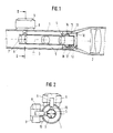
- the aiming telescope has main tube 1 within which eyepiece 2 is seated at one end and the objective at the other, front end not shown.
- main tube 1 Mounted within main tube 1 is inner tube 3 with ball-and-socket joint 4 which is disposed at the back end of inner tube 3 on the eyepiece side.
- Inner tube 3 contains inversion system 5 formed by two lenses and in front of it reticle 6 formed e.g. as cross-lines. At the front end of inner tube 3 is field lens 7.
- inner tube 3 is swiveled about ball-and-socket joint 4 with respect to main tube 1 fastened to the weapon.
- a pair of adjusting spindles 8 extend perpendicular to each other through main tube 1 at a distance from ball-and-socket joint 4, each provided with turning knob 9.
- the other end of adjusting spindle 8 acts on spherical bump 10 on inner tube 3.
- Spherical bump 10 ensures a point contact of adjusting spindle 8 on inner tube 3 in every angular position of longitudinal axis 11 of the inner tube relative to the longitudinal axis of main tube 1.
- Coil spring 12 engages at one end recess 13 facing eyepiece 2 on ball 14 of ball-and-socket joint 4 forming the joint portion fixed on the inner tube.
- Recess 13 has end wall 15 extending radially to the center of the joint, i.e. to the center of the ball, and perpendicular to longitudinal axis 11 of the inner tube.
- End wall 15 supports one end of coil spring 12, i.e. at a distance from the center of ball 14 and thus from longitudinal axis 11 of the inner tube which is greater than the outside diameter of the inner tube.
- the other end of spring 12 acts on annular projection 16 mounted on main tube 1 on the side of ball 14 facing eyepiece 2.
- Projection 16 can be formed by a threaded or snap ring which engages a corresponding thread or groove on the inner wall of main tube 1.
- Axis 17 of coil spring 12, i.e. its force, extends substantially parallel to inner tube axis 11.
- Fig. 1 shows only one spring 12. However one normally provides several, e.g. three, circumferentially distributed springs 12 between end wall 15 and annular projection 16.
- reticle 6 and field lens 7 is inserted into main tube 1 from the eyepiece side until ball 14 of ball-and-socket joint 4 hits socket 18 which extends toward the front from end wall 15 of ball 14.
- Springs 12 are then introduced and inner tube 3 and springs 12 fixed with the ring with projection 16.
Landscapes
- Physics & Mathematics (AREA)
- Optics & Photonics (AREA)
- Engineering & Computer Science (AREA)
- General Engineering & Computer Science (AREA)
- Telescopes (AREA)
- Aiming, Guidance, Guns With A Light Source, Armor, Camouflage, And Targets (AREA)
- Walking Sticks, Umbrellas, And Fans (AREA)
- Ladders (AREA)
- Fittings On The Vehicle Exterior For Carrying Loads, And Devices For Holding Or Mounting Articles (AREA)
Abstract
Description
Claims (5)
- An aiming telescope having a main tube (1) with eyepiece (2) and objective in which an inner tube is mounted with a joint (4) on the eyepiece side for receiving an inversion system and a reticle (6), a pair of adjusting spindles (8) disposed on the main tube at an angle to each other and acting on the inner tube at a distance from the joint, and at least one spring (12) for loading the inner tube against the adjusting spindles, characterized in that the joint is a ball-and-socket joint (4) and the spring (12) is supported on the ball (14) of the ball-and-socket joint (4) at a distance from the center of the ball (14), on one hand, and on the main tube (1), on the other hand.
- The aiming telescope of claim 1, characterized in that the force of the spring (12) is aligned parallel to the inner tube axis (11).
- The aiming telescope of claim 1 or 2, characterized in that the spring (12) is supported at one end on an end wall (15) of the ball (14) of the ball-and-socket joint (4), said end wall extending radially from the center of the ball (14) and perpendicular to the inner tube axis (11).
- The aiming telescope of any of the above claims, characterized in that the spring (12) is disposed on the side of the ball (14) of the ball-and-socket joint (4) facing the eyepiece (2).
- The aiming telescope of claim 4, characterized in that the spring (12) is supported at its other end on a projection (16) fastened to the main tube (1).
Applications Claiming Priority (2)
| Application Number | Priority Date | Filing Date | Title |
|---|---|---|---|
| DE4339397A DE4339397C2 (en) | 1993-11-18 | 1993-11-18 | Rifle scope |
| DE4339397 | 1993-11-18 |
Publications (3)
| Publication Number | Publication Date |
|---|---|
| EP0654650A1 EP0654650A1 (en) | 1995-05-24 |
| EP0654650B1 true EP0654650B1 (en) | 1998-10-07 |
| EP0654650B2 EP0654650B2 (en) | 2001-02-07 |
Family
ID=6502902
Family Applications (1)
| Application Number | Title | Priority Date | Filing Date |
|---|---|---|---|
| EP94109737A Expired - Lifetime EP0654650B2 (en) | 1993-11-18 | 1994-06-23 | Device for adjusting the reticle of an aiming telescope |
Country Status (4)
| Country | Link |
|---|---|
| US (1) | US5463495A (en) |
| EP (1) | EP0654650B2 (en) |
| AT (1) | ATE172024T1 (en) |
| DE (2) | DE4339397C2 (en) |
Cited By (1)
| Publication number | Priority date | Publication date | Assignee | Title |
|---|---|---|---|---|
| EP2813795A1 (en) | 2013-06-12 | 2014-12-17 | Swarovski Optik Kg | Long range optical device |
Families Citing this family (28)
| Publication number | Priority date | Publication date | Assignee | Title |
|---|---|---|---|---|
| DE4222417C2 (en) * | 1992-07-08 | 1994-06-23 | Swarovski & Co | Binoculars with additional information |
| RU2129695C1 (en) * | 1998-10-21 | 1999-04-27 | Айриян Юрий Аршакович | Device for sighting |
| CN1120993C (en) * | 1999-08-27 | 2003-09-10 | 武汉长江光电有限公司 | Quick calibration sighting telescope |
| US6469829B2 (en) * | 2001-01-09 | 2002-10-22 | Leupold & Stevens, Inc. | Equalized pivot mount for riflescope |
| ATE349669T1 (en) * | 2002-03-01 | 2007-01-15 | Carl Zeiss Optronics Wetzlar G | RIFLE SCOPE WITH INTERIOR DISPLAY |
| US6816305B2 (en) * | 2002-10-28 | 2004-11-09 | Leupold & Stevens, Inc. | Pre-assembled pivoting lens unit |
| DE10359193A1 (en) * | 2003-12-17 | 2005-07-28 | Hella Kgaa Hueck & Co. | Camera arrangement and method for adjusting a camera arrangement |
| TWI273214B (en) * | 2005-06-03 | 2007-02-11 | Asia Optical Co Inc | Sight with interference-removable magnification unit |
| US8749887B2 (en) | 2011-02-02 | 2014-06-10 | Omid S. Jahromi | Telescopic gun sight with linear optical adjustment mechanism |
| RU2501051C1 (en) * | 2012-06-09 | 2013-12-10 | Татьяна Николаевна Хацевич | Method of changing direction of axis of sight in optical sight and variable magnification sight implementing said method |
| AT513009B1 (en) * | 2012-06-11 | 2021-02-15 | Swarovski Optik Kg | Lens for an image recording device |
| US9335506B2 (en) * | 2013-03-05 | 2016-05-10 | Exelis, Inc. | Translational optic alignment locking device |
| DE102013224932B4 (en) * | 2013-12-04 | 2017-03-16 | Cassidian Optronics Gmbh | Scope |
| US10003756B2 (en) * | 2014-07-22 | 2018-06-19 | N2 Imaging Systems, LLC | Combination video and optical sight |
| US10113837B2 (en) | 2015-11-03 | 2018-10-30 | N2 Imaging Systems, LLC | Non-contact optical connections for firearm accessories |
| RU2642889C2 (en) * | 2016-05-16 | 2018-01-29 | Общество с ограниченной ответственностью "Оптическое Расчетное Бюро" | Optical sight with variable enlargement (versions) |
| AT518962B1 (en) * | 2016-07-22 | 2021-02-15 | Swarovski Optik Kg | Long-range optical device with a reticle |
| SE542668C2 (en) * | 2018-03-07 | 2020-06-23 | Aimpoint Ab | Reflex sight |
| US10753709B2 (en) | 2018-05-17 | 2020-08-25 | Sensors Unlimited, Inc. | Tactical rails, tactical rail systems, and firearm assemblies having tactical rails |
| US10645348B2 (en) | 2018-07-07 | 2020-05-05 | Sensors Unlimited, Inc. | Data communication between image sensors and image displays |
| US11079202B2 (en) | 2018-07-07 | 2021-08-03 | Sensors Unlimited, Inc. | Boresighting peripherals to digital weapon sights |
| US10742913B2 (en) | 2018-08-08 | 2020-08-11 | N2 Imaging Systems, LLC | Shutterless calibration |
| US10921578B2 (en) | 2018-09-07 | 2021-02-16 | Sensors Unlimited, Inc. | Eyecups for optics |
| US11122698B2 (en) | 2018-11-06 | 2021-09-14 | N2 Imaging Systems, LLC | Low stress electronic board retainers and assemblies |
| US10801813B2 (en) | 2018-11-07 | 2020-10-13 | N2 Imaging Systems, LLC | Adjustable-power data rail on a digital weapon sight |
| US10796860B2 (en) | 2018-12-12 | 2020-10-06 | N2 Imaging Systems, LLC | Hermetically sealed over-molded button assembly |
| US11143838B2 (en) | 2019-01-08 | 2021-10-12 | N2 Imaging Systems, LLC | Optical element retainers |
| CN111457788A (en) * | 2020-05-15 | 2020-07-28 | 中国人民解放军陆军装甲兵学院蚌埠校区 | Gun sighting telescope capable of correcting angle |
Family Cites Families (10)
| Publication number | Priority date | Publication date | Assignee | Title |
|---|---|---|---|---|
| DE249546C (en) * | ||||
| US2580280A (en) * | 1949-01-04 | 1951-12-25 | Mossberg & Sons O F | Telescope sight |
| US2627659A (en) * | 1950-03-16 | 1953-02-10 | Charles H Murr | Telescope reticle adjustment |
| US2955512A (en) * | 1956-04-03 | 1960-10-11 | Redfield Gun Sight Co | Telescope rifle sight with pivoted reticle and erector lens tube |
| FR1273278A (en) * | 1960-11-10 | 1961-10-06 | Dual-drift sight | |
| US3938875A (en) * | 1969-05-09 | 1976-02-17 | Nils Inge Algot Ruder | Sight for use on hand firearms and a method of using it |
| US4408842A (en) † | 1981-10-08 | 1983-10-11 | Leupold & Stevens, Inc. | Telescopic sight having lens holder tube with half socket pivot mount |
| DE3208814C2 (en) * | 1982-03-11 | 1985-04-18 | D. Swarovski & Co., Wattens, Tirol | Rifle scope |
| AT389003B (en) * | 1984-01-25 | 1989-10-10 | Swarovski Optik Kg | OPTICAL TARGETING |
| AT394457B (en) * | 1985-12-18 | 1992-04-10 | Basta Walter | RIFLE SCOPE WITH AUTOMATIC ELEVATION DEVICE FOR SNIPER RIFLES |
-
1993
- 1993-11-18 DE DE4339397A patent/DE4339397C2/en not_active Expired - Fee Related
-
1994
- 1994-05-18 US US08/245,420 patent/US5463495A/en not_active Expired - Lifetime
- 1994-06-23 DE DE69413781T patent/DE69413781T3/en not_active Expired - Lifetime
- 1994-06-23 AT AT94109737T patent/ATE172024T1/en not_active IP Right Cessation
- 1994-06-23 EP EP94109737A patent/EP0654650B2/en not_active Expired - Lifetime
Cited By (2)
| Publication number | Priority date | Publication date | Assignee | Title |
|---|---|---|---|---|
| EP2813795A1 (en) | 2013-06-12 | 2014-12-17 | Swarovski Optik Kg | Long range optical device |
| US9488825B2 (en) | 2013-06-12 | 2016-11-08 | Swarovski-Optik Kg. | Long-range optical device |
Also Published As
| Publication number | Publication date |
|---|---|
| DE69413781D1 (en) | 1998-11-12 |
| DE69413781T2 (en) | 1999-02-25 |
| EP0654650B2 (en) | 2001-02-07 |
| EP0654650A1 (en) | 1995-05-24 |
| DE69413781T3 (en) | 2001-05-03 |
| ATE172024T1 (en) | 1998-10-15 |
| DE4339397C2 (en) | 1996-03-07 |
| DE4339397A1 (en) | 1995-05-24 |
| US5463495A (en) | 1995-10-31 |
Similar Documents
| Publication | Publication Date | Title |
|---|---|---|
| EP0654650B2 (en) | Device for adjusting the reticle of an aiming telescope | |
| US4408842A (en) | Telescopic sight having lens holder tube with half socket pivot mount | |
| US7827727B2 (en) | Night sight and method of making the same | |
| AU683621B2 (en) | Improved night vision weapon sight | |
| CN102119353B (en) | Optical sight with both dot aiming mode and magnifying aiming mode | |
| USRE46487E1 (en) | Dot sighting device with large caliber | |
| US4582400A (en) | Periscopic eyepiece for small weapon telescopic night sights | |
| US9077139B1 (en) | Pointing devices, apparatus, systems and methods for high shock environments | |
| US6469829B2 (en) | Equalized pivot mount for riflescope | |
| US4749271A (en) | Finder scope for use with astronomical telescopes | |
| US3962795A (en) | Erector assembly retainer for telescopic rifle sights | |
| US3597040A (en) | Telescopic sight with biasing spring | |
| US4105282A (en) | Optical sight | |
| CN1004652B (en) | Observation instrument with adjustable sighting mark support | |
| US6995905B2 (en) | Sighting telescope | |
| US4978206A (en) | Periscopic sight with support means for elevation adjustment mounted within support means for azimuthal adjustment | |
| AU2020387736B2 (en) | Compact prismatic optical sight with internal zeroing method | |
| US2550962A (en) | Prism mounting for telescopes | |
| RU2054157C1 (en) | Laser collimator sight | |
| CA3161774C (en) | Compact prismatic optical sight with internal zeroing method | |
| US6057969A (en) | Lens barrel | |
| EP0246108B1 (en) | An optical device | |
| US3424521A (en) | Stabilized offset lens system | |
| JPS5850321Y2 (en) | Sighting device focusing mechanism | |
| GB191002053A (en) | Improvements in Appliances for Testing the Adjustment of Ordnance Sighting Devices. |
Legal Events
| Date | Code | Title | Description |
|---|---|---|---|
| PUAI | Public reference made under article 153(3) epc to a published international application that has entered the european phase |
Free format text: ORIGINAL CODE: 0009012 |
|
| AK | Designated contracting states |
Kind code of ref document: A1 Designated state(s): AT BE CH DE ES FR GB IT LI PT SE |
|
| 17P | Request for examination filed |
Effective date: 19950822 |
|
| 17Q | First examination report despatched |
Effective date: 19970507 |
|
| GRAG | Despatch of communication of intention to grant |
Free format text: ORIGINAL CODE: EPIDOS AGRA |
|
| GRAG | Despatch of communication of intention to grant |
Free format text: ORIGINAL CODE: EPIDOS AGRA |
|
| GRAH | Despatch of communication of intention to grant a patent |
Free format text: ORIGINAL CODE: EPIDOS IGRA |
|
| GRAH | Despatch of communication of intention to grant a patent |
Free format text: ORIGINAL CODE: EPIDOS IGRA |
|
| GRAA | (expected) grant |
Free format text: ORIGINAL CODE: 0009210 |
|
| AK | Designated contracting states |
Kind code of ref document: B1 Designated state(s): AT BE CH DE ES FR GB IT LI PT SE |
|
| PG25 | Lapsed in a contracting state [announced via postgrant information from national office to epo] |
Ref country code: ES Free format text: THE PATENT HAS BEEN ANNULLED BY A DECISION OF A NATIONAL AUTHORITY Effective date: 19981007 |
|
| REF | Corresponds to: |
Ref document number: 172024 Country of ref document: AT Date of ref document: 19981015 Kind code of ref document: T |
|
| REG | Reference to a national code |
Ref country code: CH Ref legal event code: NV Representative=s name: HUG INTERLIZENZ AG Ref country code: CH Ref legal event code: EP |
|
| REF | Corresponds to: |
Ref document number: 69413781 Country of ref document: DE Date of ref document: 19981112 |
|
| ET | Fr: translation filed | ||
| PG25 | Lapsed in a contracting state [announced via postgrant information from national office to epo] |
Ref country code: PT Free format text: LAPSE BECAUSE OF FAILURE TO SUBMIT A TRANSLATION OF THE DESCRIPTION OR TO PAY THE FEE WITHIN THE PRESCRIBED TIME-LIMIT Effective date: 19990107 |
|
| PLBQ | Unpublished change to opponent data |
Free format text: ORIGINAL CODE: EPIDOS OPPO |
|
| PLBI | Opposition filed |
Free format text: ORIGINAL CODE: 0009260 |
|
| PLBF | Reply of patent proprietor to notice(s) of opposition |
Free format text: ORIGINAL CODE: EPIDOS OBSO |
|
| 26 | Opposition filed |
Opponent name: SCHMIDT & BENDER GMBH & CO KG Effective date: 19990703 Opponent name: LEICA CAMERA AG Effective date: 19990703 |
|
| PLBF | Reply of patent proprietor to notice(s) of opposition |
Free format text: ORIGINAL CODE: EPIDOS OBSO |
|
| PLAW | Interlocutory decision in opposition |
Free format text: ORIGINAL CODE: EPIDOS IDOP |
|
| PLAW | Interlocutory decision in opposition |
Free format text: ORIGINAL CODE: EPIDOS IDOP |
|
| ITF | It: translation for a ep patent filed | ||
| PUAH | Patent maintained in amended form |
Free format text: ORIGINAL CODE: 0009272 |
|
| STAA | Information on the status of an ep patent application or granted ep patent |
Free format text: STATUS: PATENT MAINTAINED AS AMENDED |
|
| 27A | Patent maintained in amended form |
Effective date: 20010207 |
|
| AK | Designated contracting states |
Kind code of ref document: B2 Designated state(s): AT BE CH DE ES FR GB IT LI PT SE |
|
| REG | Reference to a national code |
Ref country code: CH Ref legal event code: AEN Free format text: AUFRECHTERHALTUNG DES PATENTES IN GEAENDERTER FORM |
|
| ET3 | Fr: translation filed ** decision concerning opposition | ||
| PGFP | Annual fee paid to national office [announced via postgrant information from national office to epo] |
Ref country code: GB Payment date: 20010605 Year of fee payment: 8 |
|
| PGFP | Annual fee paid to national office [announced via postgrant information from national office to epo] |
Ref country code: CH Payment date: 20010622 Year of fee payment: 8 |
|
| PGFP | Annual fee paid to national office [announced via postgrant information from national office to epo] |
Ref country code: SE Payment date: 20010625 Year of fee payment: 8 Ref country code: BE Payment date: 20010625 Year of fee payment: 8 |
|
| REG | Reference to a national code |
Ref country code: GB Ref legal event code: IF02 |
|
| PGFP | Annual fee paid to national office [announced via postgrant information from national office to epo] |
Ref country code: FR Payment date: 20020617 Year of fee payment: 9 |
|
| PG25 | Lapsed in a contracting state [announced via postgrant information from national office to epo] |
Ref country code: GB Free format text: LAPSE BECAUSE OF NON-PAYMENT OF DUE FEES Effective date: 20020623 |
|
| PG25 | Lapsed in a contracting state [announced via postgrant information from national office to epo] |
Ref country code: SE Free format text: LAPSE BECAUSE OF NON-PAYMENT OF DUE FEES Effective date: 20020624 |
|
| PG25 | Lapsed in a contracting state [announced via postgrant information from national office to epo] |
Ref country code: LI Free format text: LAPSE BECAUSE OF NON-PAYMENT OF DUE FEES Effective date: 20020630 Ref country code: CH Free format text: LAPSE BECAUSE OF NON-PAYMENT OF DUE FEES Effective date: 20020630 Ref country code: BE Free format text: LAPSE BECAUSE OF NON-PAYMENT OF DUE FEES Effective date: 20020630 |
|
| BERE | Be: lapsed |
Owner name: *SWAROVSKI OPTIK K.G. Effective date: 20020630 |
|
| EUG | Se: european patent has lapsed | ||
| GBPC | Gb: european patent ceased through non-payment of renewal fee |
Effective date: 20020623 |
|
| REG | Reference to a national code |
Ref country code: CH Ref legal event code: PL |
|
| PGFP | Annual fee paid to national office [announced via postgrant information from national office to epo] |
Ref country code: AT Payment date: 20030624 Year of fee payment: 10 |
|
| PG25 | Lapsed in a contracting state [announced via postgrant information from national office to epo] |
Ref country code: FR Free format text: LAPSE BECAUSE OF NON-PAYMENT OF DUE FEES Effective date: 20040227 |
|
| REG | Reference to a national code |
Ref country code: FR Ref legal event code: ST |
|
| PG25 | Lapsed in a contracting state [announced via postgrant information from national office to epo] |
Ref country code: AT Free format text: LAPSE BECAUSE OF NON-PAYMENT OF DUE FEES Effective date: 20040623 |
|
| PG25 | Lapsed in a contracting state [announced via postgrant information from national office to epo] |
Ref country code: IT Free format text: LAPSE BECAUSE OF NON-PAYMENT OF DUE FEES Effective date: 20050623 |
|
| PGFP | Annual fee paid to national office [announced via postgrant information from national office to epo] |
Ref country code: DE Payment date: 20110728 Year of fee payment: 18 |
|
| REG | Reference to a national code |
Ref country code: DE Ref legal event code: R119 Ref document number: 69413781 Country of ref document: DE Effective date: 20130101 |
|
| PG25 | Lapsed in a contracting state [announced via postgrant information from national office to epo] |
Ref country code: DE Free format text: LAPSE BECAUSE OF NON-PAYMENT OF DUE FEES Effective date: 20130101 |