EP0653960B1 - Magnetic stirring system - Google Patents
Magnetic stirring system Download PDFInfo
- Publication number
- EP0653960B1 EP0653960B1 EP93916072A EP93916072A EP0653960B1 EP 0653960 B1 EP0653960 B1 EP 0653960B1 EP 93916072 A EP93916072 A EP 93916072A EP 93916072 A EP93916072 A EP 93916072A EP 0653960 B1 EP0653960 B1 EP 0653960B1
- Authority
- EP
- European Patent Office
- Prior art keywords
- bottle
- stirrer bar
- stirrer
- bar
- culture
- Prior art date
- Legal status (The legal status is an assumption and is not a legal conclusion. Google has not performed a legal analysis and makes no representation as to the accuracy of the status listed.)
- Expired - Lifetime
Links
Images
Classifications
-
- B—PERFORMING OPERATIONS; TRANSPORTING
- B01—PHYSICAL OR CHEMICAL PROCESSES OR APPARATUS IN GENERAL
- B01F—MIXING, e.g. DISSOLVING, EMULSIFYING OR DISPERSING
- B01F33/00—Other mixers; Mixing plants; Combinations of mixers
- B01F33/45—Magnetic mixers; Mixers with magnetically driven stirrers
- B01F33/452—Magnetic mixers; Mixers with magnetically driven stirrers using independent floating stirring elements
Definitions
- This invention relates generally to a magnetic stirring system and in particular to a magnetic stirrer and a method of magnetically stirring a liquid within a closed culture bottle.
- Magnetic stirring of liquids within a closed bottle is a well known technique.
- a stirrer bar in the liquid to be stirred is moved with a stirring action by a magnetic field producing means outside the bottle.
- the magnetic field producing means outside the bottle may be motor driven magnets or solid state switched coils.
- the stirrer bar normally used hitherto in such systems is of relatively high quality, being strongly magnetised and costly to manufacture. Accordingly, it is normal to recover the stirrer bar after use and wash it for further use.
- Non-permanent magnet stirrer bars are driven in unspecified motion by an external permanent magnetic means driven in rotation.
- U.S. Patent No. 4 090 263 is a magnetic stirrer system in which a magnetisable stirrer bar is coupled to an external drive magnet.
- a magnetic stirrer comprising a closed culture bottle for containing liquid, the bottle containing a stirrer bar in the form of a relatively low power, lost cost disposable magnet extending parallel to the bottle base to establish opposite poles at opposite ends of the bar on opposite sides of the centre axis of the bottle through the bottle base, and a permanent magnet means located centrally beneath the bottle base in close proximity thereto and comprising a pair of spaced, relatively high power magnets providing spaced opposite poles in a plane parallel to the length of the stirrer bar in close proximity to opposite ends of the stirrer bar, and driving means for continuously rotating the external permanent magnet means about the centre axis of the bottle so that its rotating strong magnetic field aligns with that of the stirrer bar and entrains the stirrer bar in continuous rotation in a plane parallel to and above the bottle base within the liquid in the bottle.
- a method of magnetically stirring a liquid within a closed culture bottle wherein a low cost disposable stirrer bar of relatively low power magnetisation establishing opposite poles at opposite ends of the bar is inserted into the bottle to extend parallel to the bottle base across the centre axis of the bottle, a permanent magnet means of relatively high power providing spaced opposite poles in a plane parallel to the length of the stirrer bar and in close proximity to opposite ends of the stirrer bar is continuously driven in rotation beneath the bottle base in close proximity thereto and about the centre axis of the bottle, causing its rotating strong magnetic field to align with that of the stirrer bar and thereby entrain the stirrer bar in continuous rotation in a plane parallel to and above the bottle base within the liquid in the container.
- a magnetic stirrer comprising a closed culture bottle for receiving a liquid culture, a relatively low power disposable magnet constituting a stirrer bar within the bottle, said stirrer bar being moulded of non-isotropic ferrite or like material harmless to the culture to be contained in the bottle, a relatively high power permanent magnetic means outside the bottle and arranged relative to the stirrer bar for entraining the stirrer bar in continuous rotation about the centre axis of the bottle and above the bottle base within the liquid culture, and driving means for the permanent magnet means.
- a method of magnetically stirring a liquid culture within a closed culture bottle wherein a low cost disposable stirrer bar of relatively low power magnetisation is located in the bottle, said stirrer bar being made of non-isotropic ferrite or like material harmless to the culture, and a relatively high power permanent magnet means is located outside the bottle and energised to drive the stirrer bar in continuous rotation about the centre axis of the bottle and above the bottle base within the liquid culture.
- the invention is based on the realisation that an infallible magnetic coupling between an internal stirrer bar and an external magnetic driver can be achieved, with a low cost stirrer bar of low magnetisation, provided that the necessary coupling can be ensured by use of a high power magnetic drive.
- the stirrer bar is of relatively low power, it can be sufficiently cheaply made to be disposable with the liquid container.
- the stirrer bar is moulded wholly of ferrite in non-isotropic form.
- a more powerfully magnetised bar using isotropic ferrite can be produced, but manufacture involves orientating the ferrite during moulding, and this is a costly procedure.
- Such a more powerfully magnetised stirrer bar could therefore not be treated as disposable in the context of the market relating to culture bottles.
- the external magnetic drive must be of such compensatory high power as to ensure a reliable magnetic coupling. This is preferably achieved by use of a pair of spaced high power magnets respectively with north and south poles adjacent the stirrer bar. Rare earth magnets are preferred, in particular of neodymium boron.
- the stirrer bar is preferably magnetised along its longitudinal axis.
- the external permanent magnets more especially of neodymium boron, then preferably extend generally normally to the base of the container with spaced centres, and the driving means acts to rotate the magnets about an axis parallel to the lengths of the magnets and generally central between said magnets.
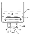
- a container 10 for example a bottle containing a culture 12, for example a blood culture, has placed within it an inexpensive stirrer bar 14 consisting of a weak magnet moulded wholly of ferrite in non-isotropic form. Because the stirrer bar 14 is cheaply manufactured, it is disposable with the culture bottle 12 after use.
- the stirrer bar 14 is moved with a stirring action within the blood culture 12 by an external magnetic driver generally referenced 16.
- the magnetic driver 16 In order to compensate for the weak magnetic power of the stirrer bar 14, the magnetic driver 16 must be of very high power, and consists of two permanent magnets 18, 20 of neodymium boron, arranged in spaced parallel relationship one with its north pole and one with its south pole adjacent the stirrer bar. These strong permanent magnets 18, 20 are driven in rotation as an assembly about an axis 22.
- the stirrer bar is a 20 mm long cylindrical component of 6 mm diameter, magnetised along its longitudinal axis, and the permanent magnets 18, 20 are each of 6 mm length and 4 mm diameter, being spaced at about 18 mm centres.
- the coupling action is achieved through the base of the bottle 10.
Landscapes
- Chemical & Material Sciences (AREA)
- Chemical Kinetics & Catalysis (AREA)
- Mixers With Rotating Receptacles And Mixers With Vibration Mechanisms (AREA)
- Apparatus Associated With Microorganisms And Enzymes (AREA)
- Mixers Of The Rotary Stirring Type (AREA)
Abstract
Description
- This invention relates generally to a magnetic stirring system and in particular to a magnetic stirrer and a method of magnetically stirring a liquid within a closed culture bottle.
- Magnetic stirring of liquids within a closed bottle is a well known technique. A stirrer bar in the liquid to be stirred is moved with a stirring action by a magnetic field producing means outside the bottle. The magnetic field producing means outside the bottle may be motor driven magnets or solid state switched coils The stirrer bar normally used hitherto in such systems is of relatively high quality, being strongly magnetised and costly to manufacture. Accordingly, it is normal to recover the stirrer bar after use and wash it for further use.
- Known from German Specification No. 1 757 099 is a magnetic stirring means for a bank of test tubes. Non-permanent magnet stirrer bars are driven in unspecified motion by an external permanent magnetic means driven in rotation. Also known from U.S. Patent No. 4 090 263 is a magnetic stirrer system in which a magnetisable stirrer bar is coupled to an external drive magnet.
- There are applications for magnetic stirrers, such as the stirring of cultures in microbiology, where the fluid is often extremely hazardous and recovery of stirrer bars would require protected sterilisation. In such circumstances, removal of the stirrer bar from the culture bottle would be a very undesirable process. Furthermore, culture bottles are themselves a disposable product, and must be of cheap manufacture. The incorporation of expensive stirrer bars in such bottles has therefore not been considered a practicable procedure, so that magnetic stirring has not been considered possible in this field of application.
- According to one aspect of the invention, there is provided a magnetic stirrer comprising a closed culture bottle for containing liquid, the bottle containing a stirrer bar in the form of a relatively low power, lost cost disposable magnet extending parallel to the bottle base to establish opposite poles at opposite ends of the bar on opposite sides of the centre axis of the bottle through the bottle base, and a permanent magnet means located centrally beneath the bottle base in close proximity thereto and comprising a pair of spaced, relatively high power magnets providing spaced opposite poles in a plane parallel to the length of the stirrer bar in close proximity to opposite ends of the stirrer bar, and driving means for continuously rotating the external permanent magnet means about the centre axis of the bottle so that its rotating strong magnetic field aligns with that of the stirrer bar and entrains the stirrer bar in continuous rotation in a plane parallel to and above the bottle base within the liquid in the bottle.
- According to another aspect of the invention, there is provided a method of magnetically stirring a liquid within a closed culture bottle, wherein a low cost disposable stirrer bar of relatively low power magnetisation establishing opposite poles at opposite ends of the bar is inserted into the bottle to extend parallel to the bottle base across the centre axis of the bottle, a permanent magnet means of relatively high power providing spaced opposite poles in a plane parallel to the length of the stirrer bar and in close proximity to opposite ends of the stirrer bar is continuously driven in rotation beneath the bottle base in close proximity thereto and about the centre axis of the bottle, causing its rotating strong magnetic field to align with that of the stirrer bar and thereby entrain the stirrer bar in continuous rotation in a plane parallel to and above the bottle base within the liquid in the container.
- According to still another aspect of the invention, there is provided a magnetic stirrer comprising a closed culture bottle for receiving a liquid culture, a relatively low power disposable magnet constituting a stirrer bar within the bottle, said stirrer bar being moulded of non-isotropic ferrite or like material harmless to the culture to be contained in the bottle, a relatively high power permanent magnetic means outside the bottle and arranged relative to the stirrer bar for entraining the stirrer bar in continuous rotation about the centre axis of the bottle and above the bottle base within the liquid culture, and driving means for the permanent magnet means.
- According to yet another aspect of the invention, there is provided a method of magnetically stirring a liquid culture within a closed culture bottle, wherein a low cost disposable stirrer bar of relatively low power magnetisation is located in the bottle, said stirrer bar being made of non-isotropic ferrite or like material harmless to the culture, and a relatively high power permanent magnet means is located outside the bottle and energised to drive the stirrer bar in continuous rotation about the centre axis of the bottle and above the bottle base within the liquid culture.
- The invention is based on the realisation that an infallible magnetic coupling between an internal stirrer bar and an external magnetic driver can be achieved, with a low cost stirrer bar of low magnetisation, provided that the necessary coupling can be ensured by use of a high power magnetic drive.
- In the field of blood culture bottles especially, a reliable magnetic coupling between the stirrer bar and its magnetic driving means is an essential requirement, because the bottle containing the sample is effectively opaque, so that visible checking of the operation of the stirrer bar is virtually impossible.
- Because the stirrer bar is of relatively low power, it can be sufficiently cheaply made to be disposable with the liquid container. Preferably, therefore, the stirrer bar is moulded wholly of ferrite in non-isotropic form. A more powerfully magnetised bar using isotropic ferrite can be produced, but manufacture involves orientating the ferrite during moulding, and this is a costly procedure. Such a more powerfully magnetised stirrer bar could therefore not be treated as disposable in the context of the market relating to culture bottles.
- For the low power stirrer bar to be reliably driven with a stirring action, the external magnetic drive must be of such compensatory high power as to ensure a reliable magnetic coupling. This is preferably achieved by use of a pair of spaced high power magnets respectively with north and south poles adjacent the stirrer bar. Rare earth magnets are preferred, in particular of neodymium boron.
- The stirrer bar is preferably magnetised along its longitudinal axis. The external permanent magnets, more especially of neodymium boron, then preferably extend generally normally to the base of the container with spaced centres, and the driving means acts to rotate the magnets about an axis parallel to the lengths of the magnets and generally central between said magnets.
- A practical magnetic stirrer and method of magnetic stirring in accordance with the invention will now be described by way of example with reference to the accompanying drawing, the single figure of which is a diagrammatic view of the stirrer.
- Referring to the illustrated example, a
container 10, for example a bottle containing aculture 12, for example a blood culture, has placed within it aninexpensive stirrer bar 14 consisting of a weak magnet moulded wholly of ferrite in non-isotropic form. Because thestirrer bar 14 is cheaply manufactured, it is disposable with theculture bottle 12 after use. - In use, the
stirrer bar 14 is moved with a stirring action within theblood culture 12 by an external magnetic driver generally referenced 16. In order to compensate for the weak magnetic power of thestirrer bar 14, themagnetic driver 16 must be of very high power, and consists of twopermanent magnets permanent magnets axis 22. - Even stronger coupling with the
stirrer bar 14 can be achieved if thepermanent magnets stirrer bar 14, reliably drawing it into alignment with thepermanent magnets permanent magnets - Typically, the stirrer bar is a 20 mm long cylindrical component of 6 mm diameter, magnetised along its longitudinal axis, and the
permanent magnets bottle 10.
Claims (10)
- A magnetic stirrer comprising a closed culture bottle (10) for containing liquid (12), the bottle containing a stirrer bar (14) in the form of a relatively low power, low cost disposable magnet extending parallel to the bottle base to establish opposite poles at opposite ends of the bar on opposite sides of the centre axis of the bottle through the bottle base, and a permanent magnet means (16) located centrally beneath the bottle base in close proximity thereto and comprising a pair of spaced, relatively high power magnets (18, 20) providing spaced opposite poles in a plane parallel to the length of the stirrer bar in close proximity to opposite ends of the stirrer bar, and driving means for continuously rotating the external permanent magnet means about the centre axis of the bottle so that its rotating strong magnetic field aligns with that of the stirrer bar and entrains the stirrer bar in continuous rotation in a plane parallel to and above the bottle base within the liquid in the bottle.
- A stirrer as claimed in claim 1, wherein the stirrer bar is moulded wholly of ferrite in non-isotropic form.
- A stirrer as claimed in claim 1 or 2, wherein the permanent magnet means comprises at least one relatively powerful rare earth magnet.
- A stirrer as claimed in claim 3, wherein the at least one relatively powerful magnet is made of neodymium boron.
- A method of magnetically stirring a liquid within a closed culture bottle, wherein a low cost disposable stirrer bar of relatively low power magnetisation establishing opposite poles at opposite ends of the bar is inserted into the bottle to extend parallel to the bottle base across the centre axis of the bottle, a permanent magnet means of relatively high power providing spaced opposite poles in a plane parallel to the length of the stirrer bar and in close proximity to opposite ends of the stirrer bar is continuously driven in rotation beneath the bottle base in close proximity thereto and about the centre axis of the bottle, causing its rotating strong magnetic field to align with that of the stirrer bar and thereby entrain the stirrer bar in continuous rotation in a plane parallel to and above the bottle base within the liquid in the container.
- A method as claimed in claim 5, applied to the stirring of a hazardous liquid in a disposable bottle.
- A magnetic stirrer comprising a closed culture bottle (10) for receiving a liquid culture (12), a relatively low power, low cost disposable magnet constituting a stirrer bar (14) within the bottle, said stirrer bar being moulded of non-isotropic ferrite, a relatively high power permanent magnetic means (16) outside the bottle and arranged in close proximity relative to the stirrer bar for entraining the stirrer bar in continuous rotation about the centre axis of the bottle and above the bottle base within the liquid culture, and driving means for the permanent magnet means.
- A magnetic stirrer according to claim 7, applied to a culture bottle for containing a blood culture.
- A method of magnetically stirring a liquid culture within a closed culture bottle, wherein a low cost disposable stirrer bar of relatively low power magnetisation is located in the bottle, said stirrer bar being made of non-isotropic ferrite, and a relatively high power permanent magnet means is located outside the bottle in close proximity relative to the stirrer bar and energised to drive the stirrer bar in continuous rotation about the centre axis of the bottle and above the bottle base within the liquid culture.
- A method according to claim 9, wherein the liquid culture is a blood culture.
Priority Applications (1)
| Application Number | Priority Date | Filing Date | Title |
|---|---|---|---|
| EP93916072A EP0653960B1 (en) | 1992-07-20 | 1993-07-14 | Magnetic stirring system |
Applications Claiming Priority (6)
| Application Number | Priority Date | Filing Date | Title |
|---|---|---|---|
| WOPCT/GB92/01327 | 1992-07-20 | ||
| PCT/GB1992/001327 WO1993003178A1 (en) | 1991-08-02 | 1992-07-20 | Microorganism growth |
| EP93301171 | 1993-02-17 | ||
| EP93301171 | 1993-02-17 | ||
| PCT/GB1993/001479 WO1994002238A1 (en) | 1992-07-20 | 1993-07-14 | Magnetic stirring system |
| EP93916072A EP0653960B1 (en) | 1992-07-20 | 1993-07-14 | Magnetic stirring system |
Publications (2)
| Publication Number | Publication Date |
|---|---|
| EP0653960A1 EP0653960A1 (en) | 1995-05-24 |
| EP0653960B1 true EP0653960B1 (en) | 1997-05-21 |
Family
ID=8214307
Family Applications (1)
| Application Number | Title | Priority Date | Filing Date |
|---|---|---|---|
| EP93916072A Expired - Lifetime EP0653960B1 (en) | 1992-07-20 | 1993-07-14 | Magnetic stirring system |
Country Status (4)
| Country | Link |
|---|---|
| US (1) | US5586823A (en) |
| EP (1) | EP0653960B1 (en) |
| AT (1) | ATE153255T1 (en) |
| DE (1) | DE69310915T2 (en) |
Families Citing this family (34)
| Publication number | Priority date | Publication date | Assignee | Title |
|---|---|---|---|---|
| GB9719774D0 (en) * | 1997-09-18 | 1997-11-19 | Glaxo Group Ltd | Device |
| US6416215B1 (en) | 1999-12-14 | 2002-07-09 | University Of Kentucky Research Foundation | Pumping or mixing system using a levitating magnetic element |
| US6758593B1 (en) | 2000-10-09 | 2004-07-06 | Levtech, Inc. | Pumping or mixing system using a levitating magnetic element, related system components, and related methods |
| KR100354137B1 (en) * | 2000-06-14 | 2002-09-28 | 박희재 | A Electro-Type Agitator And Operating Method Thereof |
| US7427501B2 (en) * | 2000-09-29 | 2008-09-23 | Becton, Dickinson And Company | System and method for optically monitoring the concentration of a gas, or the pressure, in a sample vial to detect sample growth |
| US6837613B2 (en) * | 2001-04-10 | 2005-01-04 | Levtech, Inc. | Sterile fluid pumping or mixing system and related method |
| US7762716B2 (en) * | 2000-10-09 | 2010-07-27 | Levtech, Inc. | Mixing vessel with a fluid-agitating element supported by a roller bearing |
| US7086778B2 (en) * | 2000-10-09 | 2006-08-08 | Levtech, Inc. | System using a levitating, rotating pumping or mixing element and related methods |
| US6382827B1 (en) | 2000-11-01 | 2002-05-07 | Dade Behring Inc. | Method and apparatus for mixing liquid solutions using a rotating magnet to generate a stirring vortex action |
| US6464387B1 (en) | 2000-12-05 | 2002-10-15 | Fred Stogsdill | Magnetic stirrer having a channel for fluid |
| AU2002239504A1 (en) * | 2000-12-06 | 2002-06-18 | Pharmacia Corporation | Laboratory scale milling process |
| US6467946B1 (en) | 2001-04-24 | 2002-10-22 | Dade Microscan Inc. | Method and apparatus for mixing liquid samples in a container using rotating magnetic fields |
| US7211430B2 (en) * | 2001-08-03 | 2007-05-01 | Becton, Dickinson And Company | System for stirring growth medium |
| JP4645033B2 (en) | 2001-10-03 | 2011-03-09 | リーブテック,インコーポレイテッド | Mixing bag or container having receptacle for fluid agitating element |
| US7572355B1 (en) | 2004-01-07 | 2009-08-11 | Board Of Trustees Of The University Of Arkansas | Electrochemistry using permanent magnets with electrodes embedded therein |
| EP2551676A1 (en) | 2005-03-28 | 2013-01-30 | Becton, Dickinson and Company | An improved system and method for stirring suspended solids in liquid media |
| US7763175B2 (en) * | 2005-05-17 | 2010-07-27 | The Board Of Supervisors Of Louisiana State University And Agricultural And Mechanical College | Electromagnetic probe device |
| DE102005032032B4 (en) * | 2005-07-08 | 2007-04-26 | Erbe Elektromedizin Gmbh | Medical device |
| US20070274864A1 (en) * | 2006-05-23 | 2007-11-29 | Exxonmobil Research And Engineering Company | Gas absorption testing system |
| US7520657B2 (en) * | 2006-07-14 | 2009-04-21 | Sigma-Aldrich Co. | Magnetic stirrer |
| US20100046323A1 (en) * | 2007-02-08 | 2010-02-25 | Linsheng Walter Tien | Magnetic Stirring Devices and Methods |
| US7905728B2 (en) * | 2007-10-05 | 2011-03-15 | Twister Tube, Ltd. | Device and method for generating vortex |
| DE102011012404A1 (en) * | 2011-02-25 | 2012-08-30 | Markus Herbert Zeiler | Safety catch for magnetic stirring bars |
| CA2915507A1 (en) * | 2013-06-28 | 2014-12-31 | Saint-Gobain Performance Plastics Corporation | Mixing assemblies including magnetic impellers |
| WO2015142959A1 (en) | 2014-03-17 | 2015-09-24 | Sani-Tech West, Inc. | Magnetic mixing system and method |
| DE102014009984A1 (en) | 2014-07-04 | 2016-01-07 | Ulrich Spranger | Method and device for cleaning the inner surfaces of round containers |
| US10591138B1 (en) * | 2016-01-30 | 2020-03-17 | Michael Nigel Blackdiamond | Container with internal illumination source |
| US11156353B2 (en) | 2014-12-01 | 2021-10-26 | #GlowOnTech | Container with illumination source |
| US10694829B1 (en) | 2016-01-30 | 2020-06-30 | Mike Diamonds | Smart container with illumination source |
| CH712595A1 (en) | 2016-06-17 | 2017-12-29 | Drm Dr Müller Ag | Device for mixing liquids, liquids with gases or solids in flexible disposable containers. |
| TWI623351B (en) | 2016-11-21 | 2018-05-11 | 牟敦剛 | Magnetic coupling assembly and magnetic coupling stirring device |
| US10881135B1 (en) | 2017-11-10 | 2021-01-05 | Creative Destruction, LLC | Cyclonically cooled and filtered smoking water pipe and method |
| US11805933B2 (en) * | 2019-08-28 | 2023-11-07 | National Presto Industries, Inc. | Cold brew coffee apparatus |
| US20230135266A1 (en) * | 2021-10-31 | 2023-05-04 | James A. Cox, JR. | Automatic Feeding Apparatus For An Aquarium |
Family Cites Families (4)
| Publication number | Priority date | Publication date | Assignee | Title |
|---|---|---|---|---|
| US2350534A (en) * | 1942-10-05 | 1944-06-06 | Rosinger Arthur | Magnetic stirrer |
| US2951689A (en) * | 1958-03-24 | 1960-09-06 | Halogen Insulator And Seal Cor | Magnetic stirring bar |
| US3384353A (en) * | 1967-05-31 | 1968-05-21 | Cole Parmer Instr & Equipment | Magnetic stirrer |
| US5120135A (en) * | 1989-12-13 | 1992-06-09 | Syntex (U.S.A.) Inc. | Method and apparatus for keeping particles in suspension |
-
1993
- 1993-07-14 US US08/373,254 patent/US5586823A/en not_active Expired - Lifetime
- 1993-07-14 EP EP93916072A patent/EP0653960B1/en not_active Expired - Lifetime
- 1993-07-14 AT AT93916072T patent/ATE153255T1/en not_active IP Right Cessation
- 1993-07-14 DE DE69310915T patent/DE69310915T2/en not_active Expired - Fee Related
Also Published As
| Publication number | Publication date |
|---|---|
| ATE153255T1 (en) | 1997-06-15 |
| DE69310915D1 (en) | 1997-06-26 |
| US5586823A (en) | 1996-12-24 |
| EP0653960A1 (en) | 1995-05-24 |
| DE69310915T2 (en) | 1997-11-06 |
Similar Documents
| Publication | Publication Date | Title |
|---|---|---|
| US5586823A (en) | Magnetic stirring system | |
| US5976369A (en) | Magnetic separation apparatus | |
| EP2038900B1 (en) | A method for manipulating magnetic particles in a liquid medium | |
| EP1381451B1 (en) | Method and apparatus for mixing liquid samples in a container using rotating magnetic fields | |
| EP1064988B1 (en) | Magnetic stirring method and system for mixing contents within an array of vessels | |
| US9694368B2 (en) | Magnetic reagent, magnetic reagent kit, method for treating magnetic carriers, and treatment device therefor | |
| RU2001110084A (en) | Magnetic interaction device for mixing fluid | |
| EP0589636B1 (en) | Magnetic separation method and apparatus therefor | |
| ATE411110T1 (en) | METHOD FOR ADDING MAGNETIC PARTICLES TO A LIQUID | |
| AU2002351857A1 (en) | Device and method for treating magnetic particles | |
| CN105733941A (en) | Magnetic bead separation device for nucleic acid extraction | |
| JP2002527218A (en) | Liquid stirrer with electromagnetic coupling | |
| ATE310585T1 (en) | TREATMENT METHOD FOR MAGNETIC PARTICLES AND BIOANALYSIS APPARATUS USING MAGNETS | |
| EP1262724B8 (en) | Icing machine with a magnetic drive for a scraping blade | |
| AU5278499A (en) | Device for treatment with magnetic fields | |
| EP0240862A1 (en) | Mixing apparatus and method | |
| EP0363441B1 (en) | Mixing apparatus and method | |
| WO1994002238A1 (en) | Magnetic stirring system | |
| AU2009309149A1 (en) | Magnetic force intensifying electromagnetic driving device | |
| US20180221837A1 (en) | Apparatus and method for mixing liquids | |
| US20250376652A1 (en) | Apparatus and methods for magnetically coupling bioreactor drive heads | |
| CN205925578U (en) | Magnetic bead control device based on permanent magnet | |
| US20250352964A1 (en) | Method of manufacturing a centrifugal wheel | |
| CA2956940A1 (en) | Apparatus and method for mixing liquids | |
| JPS62118757A (en) | Magnetic coupling type rotating introduction machine for vacuum equipment |
Legal Events
| Date | Code | Title | Description |
|---|---|---|---|
| PUAI | Public reference made under article 153(3) epc to a published international application that has entered the european phase |
Free format text: ORIGINAL CODE: 0009012 |
|
| 17P | Request for examination filed |
Effective date: 19950119 |
|
| AK | Designated contracting states |
Kind code of ref document: A1 Designated state(s): AT BE CH DE DK ES FR GB GR IE IT LI NL PT SE |
|
| 17Q | First examination report despatched |
Effective date: 19950718 |
|
| GRAG | Despatch of communication of intention to grant |
Free format text: ORIGINAL CODE: EPIDOS AGRA |
|
| GRAH | Despatch of communication of intention to grant a patent |
Free format text: ORIGINAL CODE: EPIDOS IGRA |
|
| GRAH | Despatch of communication of intention to grant a patent |
Free format text: ORIGINAL CODE: EPIDOS IGRA |
|
| GRAA | (expected) grant |
Free format text: ORIGINAL CODE: 0009210 |
|
| AK | Designated contracting states |
Kind code of ref document: B1 Designated state(s): AT BE CH DE DK ES FR GB GR IE IT LI NL PT SE |
|
| PG25 | Lapsed in a contracting state [announced via postgrant information from national office to epo] |
Ref country code: NL Free format text: LAPSE BECAUSE OF FAILURE TO SUBMIT A TRANSLATION OF THE DESCRIPTION OR TO PAY THE FEE WITHIN THE PRESCRIBED TIME-LIMIT Effective date: 19970521 Ref country code: GR Free format text: LAPSE BECAUSE OF FAILURE TO SUBMIT A TRANSLATION OF THE DESCRIPTION OR TO PAY THE FEE WITHIN THE PRESCRIBED TIME-LIMIT Effective date: 19970521 Ref country code: ES Free format text: THE PATENT HAS BEEN ANNULLED BY A DECISION OF A NATIONAL AUTHORITY Effective date: 19970521 Ref country code: DK Effective date: 19970521 Ref country code: BE Effective date: 19970521 Ref country code: AT Effective date: 19970521 |
|
| REF | Corresponds to: |
Ref document number: 153255 Country of ref document: AT Date of ref document: 19970615 Kind code of ref document: T |
|
| REG | Reference to a national code |
Ref country code: CH Ref legal event code: EP |
|
| REG | Reference to a national code |
Ref country code: CH Ref legal event code: NV Representative=s name: R. A. EGLI & CO. PATENTANWAELTE |
|
| REF | Corresponds to: |
Ref document number: 69310915 Country of ref document: DE Date of ref document: 19970626 |
|
| RAP2 | Party data changed (patent owner data changed or rights of a patent transferred) |
Owner name: OXOID LIMITED Owner name: UNILEVER PLC |
|
| PG25 | Lapsed in a contracting state [announced via postgrant information from national office to epo] |
Ref country code: IE Free format text: LAPSE BECAUSE OF NON-PAYMENT OF DUE FEES Effective date: 19970721 |
|
| ET | Fr: translation filed | ||
| PG25 | Lapsed in a contracting state [announced via postgrant information from national office to epo] |
Ref country code: SE Effective date: 19970821 Ref country code: PT Effective date: 19970821 |
|
| NLT2 | Nl: modifications (of names), taken from the european patent patent bulletin |
Owner name: OXOID LIMITED |
|
| NLV1 | Nl: lapsed or annulled due to failure to fulfill the requirements of art. 29p and 29m of the patents act | ||
| PLBE | No opposition filed within time limit |
Free format text: ORIGINAL CODE: 0009261 |
|
| STAA | Information on the status of an ep patent application or granted ep patent |
Free format text: STATUS: NO OPPOSITION FILED WITHIN TIME LIMIT |
|
| 26N | No opposition filed | ||
| REG | Reference to a national code |
Ref country code: GB Ref legal event code: 732E |
|
| REG | Reference to a national code |
Ref country code: GB Ref legal event code: IF02 |
|
| PGFP | Annual fee paid to national office [announced via postgrant information from national office to epo] |
Ref country code: CH Payment date: 20080620 Year of fee payment: 16 |
|
| PGFP | Annual fee paid to national office [announced via postgrant information from national office to epo] |
Ref country code: IT Payment date: 20080620 Year of fee payment: 16 |
|
| PGFP | Annual fee paid to national office [announced via postgrant information from national office to epo] |
Ref country code: DE Payment date: 20080623 Year of fee payment: 16 |
|
| PGFP | Annual fee paid to national office [announced via postgrant information from national office to epo] |
Ref country code: FR Payment date: 20080613 Year of fee payment: 16 |
|
| REG | Reference to a national code |
Ref country code: CH Ref legal event code: PL |
|
| REG | Reference to a national code |
Ref country code: FR Ref legal event code: ST Effective date: 20100331 |
|
| PG25 | Lapsed in a contracting state [announced via postgrant information from national office to epo] |
Ref country code: LI Free format text: LAPSE BECAUSE OF NON-PAYMENT OF DUE FEES Effective date: 20090731 Ref country code: FR Free format text: LAPSE BECAUSE OF NON-PAYMENT OF DUE FEES Effective date: 20090731 Ref country code: CH Free format text: LAPSE BECAUSE OF NON-PAYMENT OF DUE FEES Effective date: 20090731 |
|
| PG25 | Lapsed in a contracting state [announced via postgrant information from national office to epo] |
Ref country code: DE Free format text: LAPSE BECAUSE OF NON-PAYMENT OF DUE FEES Effective date: 20100202 |
|
| PG25 | Lapsed in a contracting state [announced via postgrant information from national office to epo] |
Ref country code: IT Free format text: LAPSE BECAUSE OF NON-PAYMENT OF DUE FEES Effective date: 20090714 |
|
| PGFP | Annual fee paid to national office [announced via postgrant information from national office to epo] |
Ref country code: GB Payment date: 20120719 Year of fee payment: 20 |
|
| REG | Reference to a national code |
Ref country code: GB Ref legal event code: PE20 Expiry date: 20130713 |
|
| PG25 | Lapsed in a contracting state [announced via postgrant information from national office to epo] |
Ref country code: GB Free format text: LAPSE BECAUSE OF EXPIRATION OF PROTECTION Effective date: 20130713 |