EP0653883A2 - Video system having a plurality of separable modules - Google Patents
Video system having a plurality of separable modules Download PDFInfo
- Publication number
- EP0653883A2 EP0653883A2 EP94118033A EP94118033A EP0653883A2 EP 0653883 A2 EP0653883 A2 EP 0653883A2 EP 94118033 A EP94118033 A EP 94118033A EP 94118033 A EP94118033 A EP 94118033A EP 0653883 A2 EP0653883 A2 EP 0653883A2
- Authority
- EP
- European Patent Office
- Prior art keywords
- signal
- signal processing
- processing section
- video
- recording
- Prior art date
- Legal status (The legal status is an assumption and is not a legal conclusion. Google has not performed a legal analysis and makes no representation as to the accuracy of the status listed.)
- Granted
Links
Images


Classifications
-
- H—ELECTRICITY
- H04—ELECTRIC COMMUNICATION TECHNIQUE
- H04N—PICTORIAL COMMUNICATION, e.g. TELEVISION
- H04N5/00—Details of television systems
- H04N5/76—Television signal recording
- H04N5/765—Interface circuits between an apparatus for recording and another apparatus
-
- G—PHYSICS
- G11—INFORMATION STORAGE
- G11B—INFORMATION STORAGE BASED ON RELATIVE MOVEMENT BETWEEN RECORD CARRIER AND TRANSDUCER
- G11B27/00—Editing; Indexing; Addressing; Timing or synchronising; Monitoring; Measuring tape travel
-
- H—ELECTRICITY
- H04—ELECTRIC COMMUNICATION TECHNIQUE
- H04N—PICTORIAL COMMUNICATION, e.g. TELEVISION
- H04N5/00—Details of television systems
- H04N5/76—Television signal recording
- H04N5/765—Interface circuits between an apparatus for recording and another apparatus
- H04N5/77—Interface circuits between an apparatus for recording and another apparatus between a recording apparatus and a television camera
- H04N5/772—Interface circuits between an apparatus for recording and another apparatus between a recording apparatus and a television camera the recording apparatus and the television camera being placed in the same enclosure
Definitions
- the present invention relates to a video system; and, more particularly, to a video system having a plurality of separable modules.
- Video systems may be grouped into home use equipment and potables.
- the home use equipment may be employed to record and/or reproduce a television program received through its built-in type tuner, while the portable system is intended to record, e. g., an image photographed by its built-in camera.
- a battery is normally furnished to power the portable apparatus.
- U. S. Patent No. 4,899,231 issued to Masaya Maeda et al. discloses a portable video system, having a reduced size and the weight, comprises a recording device such as a video tape recorder, a video camera as a signal source and a reproduction unit, which are separable each other as independent modules.
- the recording device is combined with the video camera for the purpose of recording an image obtained through the video camera and combined with the reproduction unit for the reproduction of the recorded image.
- the portable video system has a complicated construction since the recording device and the reproducing unit have their corresponding signal processing units. Further, the recording device should always be carried by an user even if no recording function achieved by the recording device is necessary because a source signal generated from the video camera passes through the recording device.
- a video system which comprises a main body having a signal processing section, a signal recording/reproducing section and a coupling device, and a plurality of independent modules which are separably engaged with the main body through the use of the coupling device, said modules including a camera module for providing a camera video signal to the signal processing section, a tuner module for providing a broadcast signal to the signal processing section, a computer interface module for providing a digital data signal to the signal processing section and a display module for displaying the output signal provided from the signal processing section, wherein the signal processing section includes a system controller, a coupling sensing device connected to the system controller for detecting the connection status of each of the modules to the main body, and a digital signal processor connected to the system controller for processing an input signal provided to the signal processing section in a digital format.
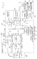
- FIG. 1 there is shown a block diagram of a video system having a main body 100 together with separable modules including a camera module 400, a tuner module 500, a display or monitor module 600 and an external digital signal processing system interface module 700, which are independent from the main body 100 and integrally formed as one system by a suitable mechanical coupling mechanism, e. g., a cable or a collet chuck in accordance with the invention.
- the main body 100 generally includes a signal processing section 200, a recording/reproducing section 300 which may be detachable from the signal processing section 200 and a number of coupling sensing devices 41, 51, 61 and 71 adapted to sense the connection status of each of the separable modules 400, 500, 600 and 700 to the main body 100.
- each of the corresponding connection sensing signals indicative of the connection status is generated from each of the corresponding coupling sensing devices 41, 51, 61 and 71.
- the signal processing section 200 comprises a system controller 10 for controlling the video system and a DSP (digital signal processor) 20 connected to the system controller 10.
- the DSP 20 is designed to process an input signal thereto in a digital format pursuant to JPEG (Joint Photographic Experts Group) standard which is a general-purpose compression standard designed to meet the needs of continuous-tone, still-image applications and the like and which is an algorithm for coding still pictures.
- JPEG Joint Photographic Experts Group
- a front panel controller 15 is connected to the system controller 10 and has sensing ports 42, 52, 62 and 72 to receive the coupling sensing signals generated from the coupling sensing devices 41, 51, 61 and 71, respectively.
- a key matrix (not shown) having a plurality of mode selection keys thereon for allowing the video system to operate in a mode selected by any one of the mode selection keys.
- the recording/reproducing section 300 has a servo controller 30 connected to the system controller 10, a motor 32 under the control of the servo controller 30, a pair of recording and reproducing heads 34 and 36, an encoder 38 connected to the input of the recording head 34, a detector 40 connected to the output of the reproducing head 36.
- an output signal from the DSP 20 is provided through a terminal 14 to the encoder 38 in the recording/reproducing section 300 for the recording thereof.
- the encoder 38 encodes the output signal from the DSP 20 to produce a PCM (pulse code modulated) signal which is obtained by performing a sampling operation on the output video signal from the DSP 20.
- PCM pulse code modulated
- the PCM signal is then recorded on a recording medium such as a magnetic tape 18 through the use of the recording head 34.
- a video signal recorded on the recording medium 18 is reproduced by the reproducing head 36.
- the reproduced video signal is of the PCM signal which may be a differentiated signal. Therefore, the reproduced PCM signal is subjected to an integration process by the detector 40 which may be an integration circuit.
- the output of the detector 40 is provided to a decoder 48.
- the decoder 48 decodes the output video signal and provides the decoded video signal to the DSP 20 through a terminal 16.
- Fig. 2 shows a block diagram of the video camera module 400 shown in Fig. 1.
- An auto-focusing ("AF") circuit 60 serves to increase or decrease the aperture size and the exposure of a lens 52 under the control of a control unit 62.
- the lens 52 functions to focus an optical image of an object onto an image pickup element such as a charge coupled device (“CCD") 54.
- CCD 54 is scanned by the control unit 62 to form a video signal in a digital form.
- the digital video signal is supplied to a Y/C (luminance/chrominance) processor 56.
- the digital video signal is subjected to a digital processing such as gamma correction and separated into a luminance signal "Y” and a chrominance signal "C".
- Both of the luminance signal Y and the chrominance signal C are supplied to an encoder 58 and the signal processing section 200 through Y and C input terminals 64 and 66 in the signal processing section 200.
- the encoder 58 serves to combine the luminance signal Y and the chrominance signal C to produce a composite video signal or a radio frequency ("RF") modulated video signal by modulating the composite video signal.
- the composite video signal is provided through a LINE input terminal 44 to the signal processing section 200 or the monitor module 600 and the RF modulated signal may be provided through a terminal 46 to another video system such as a television set or a video cassette recorder.
- the camera module 400 may be combined to the main body 100 through the use of a conventional cable connection or a mechanical connector such as a hot shoe.
- the coupling sensing device 41 signals the connection status to the panel controller 15 through the input port 42.
- the video signal through the LINE input terminal 44 from the camera module 400 is supplied to an ADC (analog to digital converter) 82 which performs an analog-to-digital conversion.
- the digitized video signal by the ADC 82 is applied to a Y/C processor 86.
- the Y/C processor 86 combines the digitized video signal with the Y and C signals via the terminal 64 and 66 from the camera module 400 and encodes the combined video signal. Thereafter, the encoded signal by the Y/C processor 86 is supplied to the DSP 20 for the processing thereof.
- Fig. 3 shows a block diagram of the monitor module 600 shown in Fig. 1.
- the monitor module 600 may be connected to the main body 100 by a conventional cable connection.
- the coupling sensing device 61 signals the connection status to the panel controller 15 through the input port 62.
- the output video signal from the DSP 20 is supplied via a DAC (digital-to-analog converter) 90 to the monitor module 600.
- a liquid crystal display (“LCD") controller 94 receives through an input terminal 92 the video signal which is converted into an analog form by the DAC 90.
- the analog video signal is subjected to a signal format conversion process to produce a converted video signal capable of being displayed on a LCD display 96.
- the monitor module 600 may be directly coupled to the camera module 400 through a mechanical coupling device such as a collet chuck in order to display the composite video signal provided through the terminal 46 in the camera module 400.
- Fig. 4 shows a block diagram of the tuner module 500 shown in Fig. 1.
- a radio frequency (“RF") tuner 104 receives an external broadcasting signal through a receiving antenna 102 and converts it to an intermediate frequency (IF) signal with a single band of frequencies. The converted IF signal is supplied to an IF amplifier and divided into an IF video signal and an IF audio signal.
- a video detector 108 receives the IF video and audio signals and provides a baseband video signal and a baseband audio signal to a sound trap circuit 110 and a series of a high pass filter (“HFP”) 114 and a band pass filter (“BPF”) 116, respectively.
- HFP high pass filter
- BPF band pass filter
- the sound trap circuit 110 extracts a remaining sound signal component from the baseband video signal and supplies the baseband video signal to the main body 100 via a buffer 112.
- the baseband audio signal is converted to a sound signal with an appropriate audio band while passing the series of the HPF 114 and the BPF 116 and supplied to a sound detector 118. And then, the output of the sound detector 118 is provided to the main body 100 through a terminal 122.
- the tuner module 500 is connected to the main body 100 through the use of a mechanical coupling device such as a collet chuck so that the video and the audio signals are collectively provided to the main body 100 through the collet chuck.
- the coupling sensing device 51 signals the connection status of the tuner module 500 to the main body 100 to the panel controller 15 through the input port 52.
- the video signal through the terminal 120 from the tuner 500 is supplied to an ADC 124 which performs an analog-to-digital conversion and then a Y/C processor 126.
- the Y/C processor 126 performs a Y/C signal processing on the digital video signal converted from the ADC 124 and then encodes the same.
- the output of the Y/C processor 126 is provided to the DSP 20 for the processing thereof.
- the audio signal from the tuner module 500 is supplied through a low pass filter ("LPF") 128 to an ADC 130 for its conversion into a digital form.
- LPF low pass filter
- the converted digital audio signal is then applied to the DSP 20 for the processing thereof.
- the processed video and audio signals by the DSP 20 may be supplied to the recording/reproducing section 300 for the recording thereof or provided to the monitor module 600 for displaying thereof.
- Fig. 5 shows a block diagram of the external digital signal processing system interface module 700 which may be coupled by a conventional cable connection to the main body 100.
- the external digital signal processing system interface module 700 is used to allow the recording/reproducing section 300 to be employed as an auxiliary storage device of an external digital signal processing system such as a personal computer ("PC") (not shown).
- the PC interface module 700 includes a serial/parallel (S/P) register 134, a parallel/serial (P/S) register 146 and an interface controller 148 which is connected through a terminal 138 between the system controller 10 in the main body 100 and a CPU (central processing unit) or a SCSI (small computer system interface) which is employed in the PC.
- the interface controller 148 serves to perform the timing control, i.
- the S/P register 134 permits the output signal from the DSP 20 to convert a serial data format into a parallel data format while the P/S register 146 permits the output signal from the PC to change from a parallel data format into a serial data format.
- the converted parallel or serial signal is provided to the PC or the DSP 20 under the control of the interface controller 148, respectively.
Landscapes
- Engineering & Computer Science (AREA)
- Multimedia (AREA)
- Signal Processing (AREA)
- Television Signal Processing For Recording (AREA)
- Camera Bodies And Camera Details Or Accessories (AREA)
Abstract
Description
- The present invention relates to a video system; and, more particularly, to a video system having a plurality of separable modules.
- Video systems may be grouped into home use equipment and potables. The home use equipment may be employed to record and/or reproduce a television program received through its built-in type tuner, while the portable system is intended to record, e. g., an image photographed by its built-in camera. A battery is normally furnished to power the portable apparatus.
- U. S. Patent No. 4,899,231 issued to Masaya Maeda et al. discloses a portable video system, having a reduced size and the weight, comprises a recording device such as a video tape recorder, a video camera as a signal source and a reproduction unit, which are separable each other as independent modules. The recording device is combined with the video camera for the purpose of recording an image obtained through the video camera and combined with the reproduction unit for the reproduction of the recorded image.
- The portable video system, however, has a complicated construction since the recording device and the reproducing unit have their corresponding signal processing units. Further, the recording device should always be carried by an user even if no recording function achieved by the recording device is necessary because a source signal generated from the video camera passes through the recording device.
- It is, therefore, a primary object of the invention to provide a video system having a plurality of separable modules and a signal processing module which is designed to centrally process signals from and to the separable modules.
- In accordance with the present invention, there is provided a video system which comprises a main body having a signal processing section, a signal recording/reproducing section and a coupling device, and a plurality of independent modules which are separably engaged with the main body through the use of the coupling device, said modules including a camera module for providing a camera video signal to the signal processing section, a tuner module for providing a broadcast signal to the signal processing section, a computer interface module for providing a digital data signal to the signal processing section and a display module for displaying the output signal provided from the signal processing section, wherein the signal processing section includes a system controller, a coupling sensing device connected to the system controller for detecting the connection status of each of the modules to the main body, and a digital signal processor connected to the system controller for processing an input signal provided to the signal processing section in a digital format.
- The above and other objects and features of the present invention will become apparent from the following description of preferred embodiments taken in conjunction with the accompanying drawings, in which:
- FIG. 1 shows a schematic block diagram of a video system in accordance with the invention;
- FIG. 2 illustrates a block diagram of the camera module shown in FIG. 1;
- FIG. 3 represents a block diagram of the display or monitor module shown in FIG. 1;
- FIG. 4 provides a block diagram of the tuner module shown in FIG. 1; and
- FIG. 5 presents a block diagram of the computer interface module shown in FIG. 1.
- Referring to FIG. 1, there is shown a block diagram of a video system having a
main body 100 together with separable modules including acamera module 400, atuner module 500, a display ormonitor module 600 and an external digital signal processing system interface module 700, which are independent from themain body 100 and integrally formed as one system by a suitable mechanical coupling mechanism, e. g., a cable or a collet chuck in accordance with the invention. Themain body 100 generally includes asignal processing section 200, a recording/reproducingsection 300 which may be detachable from thesignal processing section 200 and a number ofcoupling sensing devices separable modules main body 100. As each of theseparable components main body 100, each of the corresponding connection sensing signals indicative of the connection status is generated from each of the correspondingcoupling sensing devices - The
signal processing section 200 comprises asystem controller 10 for controlling the video system and a DSP (digital signal processor) 20 connected to thesystem controller 10. The DSP 20 is designed to process an input signal thereto in a digital format pursuant to JPEG (Joint Photographic Experts Group) standard which is a general-purpose compression standard designed to meet the needs of continuous-tone, still-image applications and the like and which is an algorithm for coding still pictures. - A
front panel controller 15 is connected to thesystem controller 10 and hassensing ports coupling sensing devices panel controller 15 is a key matrix (not shown) having a plurality of mode selection keys thereon for allowing the video system to operate in a mode selected by any one of the mode selection keys. - The recording/reproducing
section 300 has aservo controller 30 connected to thesystem controller 10, amotor 32 under the control of theservo controller 30, a pair of recording and reproducingheads encoder 38 connected to the input of therecording head 34, adetector 40 connected to the output of the reproducinghead 36. In case where the recording/reproducingsection 300 is connected to themain body 100, an output signal from theDSP 20 is provided through aterminal 14 to theencoder 38 in the recording/reproducingsection 300 for the recording thereof. Theencoder 38 encodes the output signal from theDSP 20 to produce a PCM (pulse code modulated) signal which is obtained by performing a sampling operation on the output video signal from theDSP 20. The PCM signal is then recorded on a recording medium such as amagnetic tape 18 through the use of therecording head 34. On the other hand, during the reproducing operation, a video signal recorded on therecording medium 18 is reproduced by the reproducinghead 36. The reproduced video signal, however, is of the PCM signal which may be a differentiated signal. Therefore, the reproduced PCM signal is subjected to an integration process by thedetector 40 which may be an integration circuit. The output of thedetector 40 is provided to adecoder 48. Thedecoder 48 decodes the output video signal and provides the decoded video signal to the DSP 20 through aterminal 16. - Fig. 2 shows a block diagram of the
video camera module 400 shown in Fig. 1. An auto-focusing ("AF")circuit 60 serves to increase or decrease the aperture size and the exposure of alens 52 under the control of acontrol unit 62. Thelens 52 functions to focus an optical image of an object onto an image pickup element such as a charge coupled device ("CCD") 54. TheCCD 54 is scanned by thecontrol unit 62 to form a video signal in a digital form. The digital video signal is supplied to a Y/C (luminance/chrominance)processor 56. In the Y/C processor 56, the digital video signal is subjected to a digital processing such as gamma correction and separated into a luminance signal "Y" and a chrominance signal "C". Both of the luminance signal Y and the chrominance signal C are supplied to anencoder 58 and thesignal processing section 200 through Y andC input terminals signal processing section 200. Theencoder 58 serves to combine the luminance signal Y and the chrominance signal C to produce a composite video signal or a radio frequency ("RF") modulated video signal by modulating the composite video signal. The composite video signal is provided through aLINE input terminal 44 to thesignal processing section 200 or themonitor module 600 and the RF modulated signal may be provided through aterminal 46 to another video system such as a television set or a video cassette recorder. - The
camera module 400 may be combined to themain body 100 through the use of a conventional cable connection or a mechanical connector such as a hot shoe. When the combination status is achieved, thecoupling sensing device 41 signals the connection status to thepanel controller 15 through theinput port 42. At this time, the video signal through theLINE input terminal 44 from thecamera module 400 is supplied to an ADC (analog to digital converter) 82 which performs an analog-to-digital conversion. The digitized video signal by the ADC 82 is applied to a Y/C processor 86. The Y/C processor 86 combines the digitized video signal with the Y and C signals via theterminal camera module 400 and encodes the combined video signal. Thereafter, the encoded signal by the Y/C processor 86 is supplied to the DSP 20 for the processing thereof. - Fig. 3 shows a block diagram of the
monitor module 600 shown in Fig. 1. Themonitor module 600 may be connected to themain body 100 by a conventional cable connection. When the connection is made, thecoupling sensing device 61 signals the connection status to thepanel controller 15 through theinput port 62. At this time, the output video signal from the DSP 20 is supplied via a DAC (digital-to-analog converter) 90 to themonitor module 600. A liquid crystal display ("LCD")controller 94 receives through aninput terminal 92 the video signal which is converted into an analog form by theDAC 90. In theLCD controller 94, the analog video signal is subjected to a signal format conversion process to produce a converted video signal capable of being displayed on aLCD display 96. On the other hand, themonitor module 600 may be directly coupled to thecamera module 400 through a mechanical coupling device such as a collet chuck in order to display the composite video signal provided through theterminal 46 in thecamera module 400. - Fig. 4 shows a block diagram of the
tuner module 500 shown in Fig. 1. A radio frequency ("RF")tuner 104 receives an external broadcasting signal through a receivingantenna 102 and converts it to an intermediate frequency (IF) signal with a single band of frequencies. The converted IF signal is supplied to an IF amplifier and divided into an IF video signal and an IF audio signal. Avideo detector 108 receives the IF video and audio signals and provides a baseband video signal and a baseband audio signal to asound trap circuit 110 and a series of a high pass filter ("HFP") 114 and a band pass filter ("BPF") 116, respectively. Thesound trap circuit 110 extracts a remaining sound signal component from the baseband video signal and supplies the baseband video signal to themain body 100 via abuffer 112. On the other hand, the baseband audio signal is converted to a sound signal with an appropriate audio band while passing the series of the HPF 114 and the BPF 116 and supplied to asound detector 118. And then, the output of thesound detector 118 is provided to themain body 100 through a terminal 122. - The
tuner module 500 is connected to themain body 100 through the use of a mechanical coupling device such as a collet chuck so that the video and the audio signals are collectively provided to themain body 100 through the collet chuck. When thetuner module 500 is connected to themain body 100, thecoupling sensing device 51 signals the connection status of thetuner module 500 to themain body 100 to thepanel controller 15 through theinput port 52. At this time, the video signal through the terminal 120 from thetuner 500 is supplied to anADC 124 which performs an analog-to-digital conversion and then a Y/C processor 126. The Y/C processor 126 performs a Y/C signal processing on the digital video signal converted from theADC 124 and then encodes the same. The output of the Y/C processor 126 is provided to theDSP 20 for the processing thereof. At the same time, the audio signal from thetuner module 500 is supplied through a low pass filter ("LPF") 128 to an ADC 130 for its conversion into a digital form. The converted digital audio signal is then applied to theDSP 20 for the processing thereof. The processed video and audio signals by theDSP 20 may be supplied to the recording/reproducingsection 300 for the recording thereof or provided to themonitor module 600 for displaying thereof. - Fig. 5 shows a block diagram of the external digital signal processing system interface module 700 which may be coupled by a conventional cable connection to the
main body 100. The external digital signal processing system interface module 700 is used to allow the recording/reproducingsection 300 to be employed as an auxiliary storage device of an external digital signal processing system such as a personal computer ("PC") (not shown). The PC interface module 700 includes a serial/parallel (S/P)register 134, a parallel/serial (P/S)register 146 and aninterface controller 148 which is connected through a terminal 138 between thesystem controller 10 in themain body 100 and a CPU (central processing unit) or a SCSI (small computer system interface) which is employed in the PC. Theinterface controller 148 serves to perform the timing control, i. e., the synchronization of thesignal processing section 200 in themain body 100 to the PC in order to insure the communication betweenmain body 100 and the PC and controls the data conversion process to be performed in theregisters DSP 20 to convert a serial data format into a parallel data format while the P/S register 146 permits the output signal from the PC to change from a parallel data format into a serial data format. The converted parallel or serial signal is provided to the PC or theDSP 20 under the control of theinterface controller 148, respectively. - While the present invention has been shown and described with respect to the preferred embodiments, it will be apparent to those skilled in the art that many changes and modifications may be made without departing from the spirit and scope of the invention as defined in the appended claims.
Claims (2)
- A video system comprising:
a main body having a signal processing section, a recording/reproducing section and a coupling means; and
a plurality of independent modules having a camera module, a display module, a tuner module, and an external digital signal processing system interface module which are separably engaged with the main body through the coupling means, the camera module providing a camera video signal to the signal processing section, the tuner module providing a broadcast video signal to the signal processing section, the interface module providing a digital data signal to the signal processing section and the display module displaying an output video signal provided from the signal processing means,
wherein the signal processing section includes:
a system controller for controlling the video system;
a coupling sensing means connected to the system controller for detecting the connection status of each of the modules to the main body through the coupling means; and
a signal processing means connected to the system controller for processing an input signal provided to the signal processing section in a digital form to produce the output signal. - The video system of claim 1, wherein the recording/reproducing section includes:
an encoder for encoding the output signal provided from the signal processing means to produce an encoded signal for the recording thereof;
a recording/reproducing means for recording the encoded signal from the encoder on a recording medium and reproducing a prerecorded signal on the recording medium;
a detector for performing an integration process for the reproduced prerecorded signal to produce a digitized signal; and
a decoder for decoding the digitized signal from the detector to produce and send a decoded signal for the providing as the input signal to the signal processing means.
Applications Claiming Priority (2)
| Application Number | Priority Date | Filing Date | Title |
|---|---|---|---|
| KR9324382 | 1993-11-16 | ||
| KR1019930024382A KR950015275A (en) | 1993-11-16 | 1993-11-16 | Component Type Small BC |
Publications (3)
| Publication Number | Publication Date |
|---|---|
| EP0653883A2 true EP0653883A2 (en) | 1995-05-17 |
| EP0653883A3 EP0653883A3 (en) | 1995-11-02 |
| EP0653883B1 EP0653883B1 (en) | 1999-01-20 |
Family
ID=19368206
Family Applications (1)
| Application Number | Title | Priority Date | Filing Date |
|---|---|---|---|
| EP94118033A Expired - Lifetime EP0653883B1 (en) | 1993-11-16 | 1994-11-15 | Video system having a plurality of separable modules |
Country Status (5)
| Country | Link |
|---|---|
| EP (1) | EP0653883B1 (en) |
| JP (1) | JPH07203342A (en) |
| KR (1) | KR950015275A (en) |
| CN (1) | CN1046833C (en) |
| DE (1) | DE69416084T2 (en) |
Cited By (4)
| Publication number | Priority date | Publication date | Assignee | Title |
|---|---|---|---|---|
| WO2004010207A1 (en) * | 2002-07-22 | 2004-01-29 | D.Boss Co.Ltd | A display apparatus whose signal processing unit is separated |
| DE19757493B4 (en) * | 1996-12-23 | 2004-11-04 | Lg Electronics Inc. | Modular television and control methods for it |
| DE10145708B4 (en) * | 2000-09-19 | 2007-02-01 | Samsung Electronics Co., Ltd., Suwon | Apparatus and method for connecting a base module to a feature extension module in an AV system |
| EP1667374A3 (en) * | 2004-12-03 | 2009-11-18 | Sony Corporation | Apparatus connection interface, apparatus control system and method of controlling apparatus control system |
Families Citing this family (2)
| Publication number | Priority date | Publication date | Assignee | Title |
|---|---|---|---|---|
| KR100520971B1 (en) * | 1997-12-11 | 2005-12-26 | 주식회사 엘지이아이 | Interface device of video recorder |
| JP4541018B2 (en) * | 2004-04-01 | 2010-09-08 | 株式会社日立製作所 | DIGITAL BROADCAST RECEIVING DEVICE, TV DEVICE, AND DIGITAL BROADCAST RECEIVING METHOD |
Citations (3)
| Publication number | Priority date | Publication date | Assignee | Title |
|---|---|---|---|---|
| US4507689A (en) * | 1981-01-30 | 1985-03-26 | Canon Kabushiki Kaisha | Component video system and arrangement for interconnecting the same |
| US5170295A (en) * | 1989-07-18 | 1992-12-08 | Teac Corporation | Picture signal recording method and system therefor |
| US5170262A (en) * | 1985-09-13 | 1992-12-08 | Canon Kabushiki Kaisha | Electronic camera |
-
1993
- 1993-11-16 KR KR1019930024382A patent/KR950015275A/en not_active Application Discontinuation
-
1994
- 1994-11-15 DE DE69416084T patent/DE69416084T2/en not_active Expired - Fee Related
- 1994-11-15 EP EP94118033A patent/EP0653883B1/en not_active Expired - Lifetime
- 1994-11-16 JP JP6281984A patent/JPH07203342A/en active Pending
- 1994-11-16 CN CN94120178A patent/CN1046833C/en not_active Expired - Fee Related
Patent Citations (3)
| Publication number | Priority date | Publication date | Assignee | Title |
|---|---|---|---|---|
| US4507689A (en) * | 1981-01-30 | 1985-03-26 | Canon Kabushiki Kaisha | Component video system and arrangement for interconnecting the same |
| US5170262A (en) * | 1985-09-13 | 1992-12-08 | Canon Kabushiki Kaisha | Electronic camera |
| US5170295A (en) * | 1989-07-18 | 1992-12-08 | Teac Corporation | Picture signal recording method and system therefor |
Non-Patent Citations (1)
| Title |
|---|
| HITACHI REVIEW, vol. 41, no. 2, May 1992 TOKYO JP, pages 97-102, TAGUCHI 'video cassette recorder technology trends as supported by microcontrollers' * |
Cited By (7)
| Publication number | Priority date | Publication date | Assignee | Title |
|---|---|---|---|---|
| DE19757493B4 (en) * | 1996-12-23 | 2004-11-04 | Lg Electronics Inc. | Modular television and control methods for it |
| DE10145708B4 (en) * | 2000-09-19 | 2007-02-01 | Samsung Electronics Co., Ltd., Suwon | Apparatus and method for connecting a base module to a feature extension module in an AV system |
| WO2004010207A1 (en) * | 2002-07-22 | 2004-01-29 | D.Boss Co.Ltd | A display apparatus whose signal processing unit is separated |
| EP1530742A1 (en) * | 2002-07-22 | 2005-05-18 | D.Boss Co.Ltd | A display apparatus whose signal processing unit is separated |
| EP1530742A4 (en) * | 2002-07-22 | 2009-05-13 | Boss Co Ltd D | A display apparatus whose signal processing unit is separated |
| EP1667374A3 (en) * | 2004-12-03 | 2009-11-18 | Sony Corporation | Apparatus connection interface, apparatus control system and method of controlling apparatus control system |
| US7840715B2 (en) | 2004-12-03 | 2010-11-23 | Sony Corporation | Apparatus connection interface, apparatus control system and method of controlling apparatus control system |
Also Published As
| Publication number | Publication date |
|---|---|
| CN1046833C (en) | 1999-11-24 |
| KR950015275A (en) | 1995-06-16 |
| EP0653883B1 (en) | 1999-01-20 |
| EP0653883A3 (en) | 1995-11-02 |
| JPH07203342A (en) | 1995-08-04 |
| DE69416084D1 (en) | 1999-03-04 |
| CN1113059A (en) | 1995-12-06 |
| DE69416084T2 (en) | 1999-08-05 |
Similar Documents
| Publication | Publication Date | Title |
|---|---|---|
| US6480671B2 (en) | Video camera and recording and reproducing apparatus which communicate via wireless communication techniques | |
| JP4431620B2 (en) | Imaging device | |
| EP0653883B1 (en) | Video system having a plurality of separable modules | |
| JP3104085B2 (en) | Transmission system for recording / reproducing device | |
| US5903703A (en) | Recording apparatus and reproduction apparatus storing data of a number of subframes | |
| JPH10174032A (en) | Digital recording video camera | |
| JP3700868B2 (en) | Optical system separation type signal recording / reproducing apparatus | |
| JP2886889B2 (en) | Electronic still camera | |
| US5455718A (en) | Double deck camcorder | |
| KR940007471B1 (en) | Double-deck camcoder | |
| JPH08279942A (en) | Signal processor and extension adaptor used for the processor | |
| JP4011904B2 (en) | Video camera and control method | |
| JPH0822042B2 (en) | Electronic camera | |
| JPH0983854A (en) | Sound collection device for camera | |
| KR100520971B1 (en) | Interface device of video recorder | |
| KR100282942B1 (en) | Fade processing unit of digital video camera | |
| JPH0715697A (en) | Dubbing controller for image processing equipment | |
| JP2001298648A (en) | Video recording and reproducing device | |
| JP3170511B2 (en) | Video camera and video camera control method | |
| JP2000078458A (en) | Image pickup recording and reproducing device and operation control method therefor | |
| JP2000004043A (en) | Image information treatment device | |
| KR100297817B1 (en) | Video camera having a digital specification effect function during reproduction | |
| JPH09186969A (en) | Magnetic recording and reproducing device | |
| JPH06342586A (en) | Information recording and reproducing device | |
| JPH07274111A (en) | Video/audio signal recording and reproducing device |
Legal Events
| Date | Code | Title | Description |
|---|---|---|---|
| PUAI | Public reference made under article 153(3) epc to a published international application that has entered the european phase |
Free format text: ORIGINAL CODE: 0009012 |
|
| AK | Designated contracting states |
Kind code of ref document: A2 Designated state(s): DE FR GB NL |
|
| PUAL | Search report despatched |
Free format text: ORIGINAL CODE: 0009013 |
|
| AK | Designated contracting states |
Kind code of ref document: A3 Designated state(s): DE FR GB NL |
|
| 17P | Request for examination filed |
Effective date: 19960430 |
|
| GRAG | Despatch of communication of intention to grant |
Free format text: ORIGINAL CODE: EPIDOS AGRA |
|
| 17Q | First examination report despatched |
Effective date: 19980211 |
|
| GRAG | Despatch of communication of intention to grant |
Free format text: ORIGINAL CODE: EPIDOS AGRA |
|
| GRAH | Despatch of communication of intention to grant a patent |
Free format text: ORIGINAL CODE: EPIDOS IGRA |
|
| GRAH | Despatch of communication of intention to grant a patent |
Free format text: ORIGINAL CODE: EPIDOS IGRA |
|
| GRAA | (expected) grant |
Free format text: ORIGINAL CODE: 0009210 |
|
| AK | Designated contracting states |
Kind code of ref document: B1 Designated state(s): DE FR GB NL |
|
| REF | Corresponds to: |
Ref document number: 69416084 Country of ref document: DE Date of ref document: 19990304 |
|
| ET | Fr: translation filed | ||
| PG25 | Lapsed in a contracting state [announced via postgrant information from national office to epo] |
Ref country code: DE Free format text: LAPSE BECAUSE OF FAILURE TO SUBMIT A TRANSLATION OF THE DESCRIPTION OR TO PAY THE FEE WITHIN THE PRESCRIBED TIME-LIMIT Effective date: 19990421 |
|
| PGFP | Annual fee paid to national office [announced via postgrant information from national office to epo] |
Ref country code: FR Payment date: 19991109 Year of fee payment: 6 |
|
| PGFP | Annual fee paid to national office [announced via postgrant information from national office to epo] |
Ref country code: GB Payment date: 19991110 Year of fee payment: 6 |
|
| PGFP | Annual fee paid to national office [announced via postgrant information from national office to epo] |
Ref country code: DE Payment date: 19991115 Year of fee payment: 6 |
|
| PLBE | No opposition filed within time limit |
Free format text: ORIGINAL CODE: 0009261 |
|
| STAA | Information on the status of an ep patent application or granted ep patent |
Free format text: STATUS: NO OPPOSITION FILED WITHIN TIME LIMIT |
|
| PGFP | Annual fee paid to national office [announced via postgrant information from national office to epo] |
Ref country code: NL Payment date: 19991130 Year of fee payment: 6 |
|
| 26N | No opposition filed | ||
| PG25 | Lapsed in a contracting state [announced via postgrant information from national office to epo] |
Ref country code: GB Free format text: LAPSE BECAUSE OF NON-PAYMENT OF DUE FEES Effective date: 20001115 |
|
| PG25 | Lapsed in a contracting state [announced via postgrant information from national office to epo] |
Ref country code: NL Free format text: LAPSE BECAUSE OF NON-PAYMENT OF DUE FEES Effective date: 20010601 |
|
| GBPC | Gb: european patent ceased through non-payment of renewal fee |
Effective date: 20001115 |
|
| PG25 | Lapsed in a contracting state [announced via postgrant information from national office to epo] |
Ref country code: FR Free format text: LAPSE BECAUSE OF NON-PAYMENT OF DUE FEES Effective date: 20010731 |
|
| NLV4 | Nl: lapsed or anulled due to non-payment of the annual fee |
Effective date: 20010601 |
|
| REG | Reference to a national code |
Ref country code: FR Ref legal event code: ST |