EP0653221B1 - Needleless connector medical site - Google Patents
Needleless connector medical site Download PDFInfo
- Publication number
- EP0653221B1 EP0653221B1 EP94203665A EP94203665A EP0653221B1 EP 0653221 B1 EP0653221 B1 EP 0653221B1 EP 94203665 A EP94203665 A EP 94203665A EP 94203665 A EP94203665 A EP 94203665A EP 0653221 B1 EP0653221 B1 EP 0653221B1
- Authority
- EP
- European Patent Office
- Prior art keywords
- housing
- female luer
- medical site
- aperture
- luer connector
- Prior art date
- Legal status (The legal status is an assumption and is not a legal conclusion. Google has not performed a legal analysis and makes no representation as to the accuracy of the status listed.)
- Expired - Lifetime
Links
Images


Classifications
-
- A—HUMAN NECESSITIES
- A61—MEDICAL OR VETERINARY SCIENCE; HYGIENE
- A61M—DEVICES FOR INTRODUCING MEDIA INTO, OR ONTO, THE BODY; DEVICES FOR TRANSDUCING BODY MEDIA OR FOR TAKING MEDIA FROM THE BODY; DEVICES FOR PRODUCING OR ENDING SLEEP OR STUPOR
- A61M39/00—Tubes, tube connectors, tube couplings, valves, access sites or the like, specially adapted for medical use
- A61M39/02—Access sites
-
- A—HUMAN NECESSITIES
- A61—MEDICAL OR VETERINARY SCIENCE; HYGIENE
- A61M—DEVICES FOR INTRODUCING MEDIA INTO, OR ONTO, THE BODY; DEVICES FOR TRANSDUCING BODY MEDIA OR FOR TAKING MEDIA FROM THE BODY; DEVICES FOR PRODUCING OR ENDING SLEEP OR STUPOR
- A61M39/00—Tubes, tube connectors, tube couplings, valves, access sites or the like, specially adapted for medical use
- A61M39/10—Tube connectors; Tube couplings
Definitions
- This invention relates to medical sites, in particular to sample sites through which fluids are injected or withdrawn from a patient's circulatory system and, more particularly, to a sample site which does not require use of a needle for injecting or withdrawing samples and in which the access port is easily reached for disinfecting.
- Sample sites for obtaining fluid access to a patient's circulatory system are well known.
- a catheter inserted into a patient's blood vessel may be connected to a sample site such as shown in U.S. Patent No. 4,874,377 .
- the sample site may be in-line with tubing connecting the catheter to a blood pressure monitoring transducer and/or a supply of saline or other solution, such as shown in U.S. Patent 5,148,811 , entitled “Method and Apparatus for Sampling Blood", and which is a continuation-in-part of U.S. Patent No. 5,048,537 .
- Typical of such sites is that they include a housing having a liquid path extending therein and which is to be coupled to the patient's circulatory system to make the fluid connection such as through a catheter and/or the tubing of an intravenous system, for example, like the blood pressure monitoring apparatus shown in the aforementioned U.S. Patents 5,148,811 and 5,048,537 .
- a sample site further typically includes an access port through which fluids may be introduced into the patient's circulatory system or from which blood may be withdrawn from the patient, both via the liquid path.
- a needle may be received through a resilient stopper in the access port and on into the liquid path to couple a syringe or the like attached to the needle with the patient's circulatory system for injection/withdrawal of fluids.
- a syringe or the like attached to the needle with the patient's circulatory system for injection/withdrawal of fluids.
- sampling sites requiring use of a needle present significant risk from needle sticks.
- needle sticks provide a mechanism for transfer of dangerous diseases, such as hepatitis or AIDS.
- sampling sites provide an access port adapted for needleless connection with an external fluidic system such as a syringe or tubing.
- an external fluidic system such as a syringe or tubing.
- a cylindrical reservoir is provided on the sample site to provide a confined conduit between the needleless connector such as a male luer connector and a valve assembly within the sample site.
- the stopcock side port shown in Figure 5 in the aforementioned U.S. Patent 5,148,811 in which the external fluidic system is connected thereto by securing the cuff of a male luer lock connector to the flanged top of a reservoir defined by the cylindrical wall of a female luer connector.
- a blunt cannula such as the tip or taper of a male luer connector
- the male luer connector tip impacts the valve assembly at the bottom of the female luer connector reservoir causing the valve to deflect and open under pressure of the tip of the male luer connector thereagainst.
- the valve assembly opens, a channel for fluid communication between the liquid path within the sample site and the external fluidic system is created.
- European Patent Application 0309771 describes a needleless sample site comprising a housing having a cylindrical aperture extending from an exterior wall through which a blunt cannula enters to make a connection to a liquid path.
- a seal is located in the aperture which is operable under pressure of the blunt cannula.
- a gap is provided between the aperture wall and the seal to accommodate expansion of the latter on opening thereof.
- the invention provides a medical site for use with a medical male luer connector having a blunt male tip with a luer taper, as described in claim 1.
- the present invention provides the benefits of a needleless sample site, while reducing the risk of contamination and bacterial growth.
- the reservoir above the valve assembly is eliminated and replaced with structure extending above the access port to provide the function of guiding a male luer connector taper against a seal member, but without a reservoir wall to obstruct ready access to the surface of the valve assembly for disinfecting.
- the structure may be arms which may be flanged to provide the function of locking a male luer lock connector thereto.
- the access port is defined by an apertured exterior wall of the sample site housing through which the taper of a male luer connector is to be received.
- the outer surface of the seal member which is contained within the housing normally blocks the aperture.
- the exterior wall adjacent the aperture and the outer surface of the seal member are easily wiped clean and, thus, are considered to be generally flush in the closed position of the seal member. Consequently, there is no reservoir defined about the aperture and seal surface from which contaminants or bacteria may be difficult to remove.
- the seal member is deflectable under pressure of the taper of a male luer connector passing into the aperture so as to open the seal member and provide fluid access to the liquid path in the sample site.
- the seal shuts to again block the aperture, but because there is no confined reservoir above the aperture, the exposed surface of the seal member and portions of the exterior wall adjacent the aperture (as well as the flanged arms) are readily accessible to a clinician for purposes of disinfecting the access port, such as by a wiping action between the flanged arms in a direction generally parallel the seal member and/or exterior wall surfaces. Consequently, there is less opportunity for contamination or bacterial growth with the sampling site of the present invention.
- a female luer connector function is provided atop the access port but without the cylindrical reservoir normally provided thereby.
- structure preferably in the form of a pair of arms, is provided adjacent the access port aperture such as to matingly receive a male luer connector taper therethrough while still providing generally unobstructed wiping access to the outer surface of the seal member and portions of the housing exterior wall adjacent the aperture.
- the arms may be flanged to lock the male luer connector thereto such that the arms may be seen as separate portions of a female luer connector and may thus be referred to as a split luer.
- the female luer connector portions or flanged arms are fixedly mounted to the housing exterior wall adjacent the aperture such that the inner or confronting surfaces of the flanged arms define an imaginary female luer connector cylinder about the aperture, but without the impediment of a complete cylindrical wall.
- the flanged arms are moveable from an operative position about the aperture to provide the female luer connector function to an inoperative position away from the sample site housing to provide completely unobstructed access to the outer surface of the seal member, as well as to the annular portion of the housing exterior wall completely surrounding the aperture.
- the flanged arms are mounted to the end of hinge arms so as to be moveable toward and away from the aperture.
- the hinge arms may be fixedly connected at their extreme ends to the housing and remote from the aperture and normally biased to urge the flanged arms away from the aperture. The hinge arms may then be compressed toward the sample site housing bringing the flanged arms adjacent the aperture for connecting to the male luer connector.
- the hinge arms may be slidably connected to the housing for sliding the flanged arms between the operative and inoperative positions. With the hinge arms connected to a frame member slidably disposed on a side of the housing opposite the access port, the hinge arms will ride along the side of the housing therebetween. In that event, the hinge arms are normally biased toward the housing to urge the flanged arms toward the aperture. As the frame member slides away from the access port, the hinge arms are pushed apart by the housing to separate the flanged arms and allow them to pass down over the side of the housing completely exposing the exterior wall and seal surface for disinfecting.
- a sample site with a flush-mounted needleless access port and a split or female luer structure including female luer connector portions so as to properly connect a male luer connector to the access port, but without obstructing wiping access to the seal member and surrounding regions of the housing for purposes of disinfection.
- Sample site 10 is defined by a cylindrical housing 12 having a liquid path 14 extending therein. At opposite ends of path 14 are female luer connector port 16 and male taper port 18 for connection with tubing or the like, such as for fluid communication with a patient's circulatory system (see Fig. 7 ).
- Housing 12 includes a needleless connector access port 20 between ports 16 and 18 defined along generally a planar, top exterior wall 22 of housing 12. Wall 22 includes an aperture 24 through which is to be received the tip or taper 26 of a male luer connector 28 for fluid communication with liquid path 14. Aperture 24 is sized to closely surround taper 26 when received therethrough.
- a valve assembly is provided at aperture 24 and within recess 30 of housing 12 between top wall 22 and liquid path 14 by frustro-conical actuating member 32 fixedly positioned within housing 12 and a seal member 38.
- Actuating member 32 includes a lumen 34 therethrough transverse to and in fluid communication with liquid path 14. Lumen 34 is aimed at and sealed-off by normally closed channel 36 of diaphragm 37 of resilient seal member 38 positioned over actuator member 32.
- Seal member 38 includes tubular shaped hub 42 extending below seal upper surface 40 and with frustro-conical biassing portion 47 of hub 42 seated over actuating member 32.
- the top surface 40 of seal member 38 is generally flush top wall 22 when it is closed against or adjacent aperture 24.
- the thickness of wall 22 adjacent aperture 24 is relatively thin in comparison to the length of the male luer connector tip 26 so as not to define a reservoir wall relative tip 26.
- Exterior wall 22 may be about 0.035-0.040 inches (0.9-1.0 mm) thick such that a wipe (not shown) passed across wall 22 will easily disinfect wall 22 and surface 40 without creating a well or reservoir for contaminants or bacteria to accumulate out of reach of the wipe as it passes across top wall 22.
- surface 40 may protrude from aperture 24.
- upper surface 40 of seal member 38 may be considered generally flush top wall 22 in the closed position inasmuch as the surface of the valve assembly is readily accessible to be wiped with disinfectant by wiping across top wall 22 from one side to the other.
- seal member 38 under pressure from male lumen connector taper 26 against upper surface 40, seal member 38 deflects toward liquid path 14 and drives hub 42 against the conical surface of projection 32. As hub 42 rides over projection 32, channel 36 is caused to open revealing lumen 34 for fluid communication via tip 26 between liquid path 14 and an external fluidic system coupled to connector 28 such as a syringe 44 or tubing (not shown).
- connector 28 such as a syringe 44 or tubing (not shown).
- the outer wall 45A of seal member 38 is in contact with housing 12 and the inner wall 45B thereof defines a passage 45C for fluid to pass between lumen 34 and taper 26.
- seal member 38 and biassing portion 47 urges channel 36 closed and also causes hub 42 to ride up frustro-conical actuating member 32 and reseal aperture 36 with outer surface 40 again adjacent aperture 24 and generally flush top wall 22.
- a split luer arrangement is provided.
- a pair of flanged arms 46, 48 extending upwardly and away from top wall 22 are a pair of flanged arms 46, 48. Arms 46, 48 are attached to top wall 22 at spaced apart locations adjacent aperture 24 such that the arcuate inner surfaces 50 of the arms define an imaginary cylinder 52 (shown in phantom line in Fig. 2 ) corresponding to the inner surface of a female luer connector cylinder.
- flanges 54 of arms 46, 48 define an imaginary flange thread plane 56 (also shown in phantom line in Fig.
- Arms 46, 48 thus define a pair of spaced apart female luer connector portions.
- inner surface 50 and flange 54 of each arm 46, 48 define approximately fifteen percent (15%) of the circumference of a female luer connector cylinder and/or flange (a combined total of 30%) to thereby functionally provide the female luer connector functions of guiding tip 26 and locking connector 28 in place, respectively, while leaving access port 20 otherwise generally unobstructed.
- a clinician may readily disinfect access port 20 and flange arms 46, 48 by wiping across the surface of top wall 22 such as in the direction from port 16 to port 18 with a disinfectant material such as with an alcohol wipe to disinfect the area about aperture 24.
- the needless sample site of the present invention eliminates the need to use needles with their attendant risks, while greatly reducing the risk of contamination and bacterial growth normally of great concern with prior needleless sample sites.
- FIG. 5 An alternative embodiment 60 of a sample site is shown in Fig. 5 .
- Sample site 60 is substantially similar to sample site 10 with the exception of the provision of a modified split luer connector.
- the entire surface of top wall 22 may be completely freed from obstruction by placing the split luer in an inoperative position.
- the split luer of embodiment 60 is provided by a pair of hinge arms 62, 64 connected such as by sonic welding or glue to bottom wall 65 of housing 12 and defining at their extremities a pair of female luer connector portions or flanged arms 66, 68.
- Hinge arms 62, 64 may be living hinges and are normally in an inoperative position shown in dashed line in Fig. 5 with arms 66, 68 outwardly of housing 12 so as to expose the entirety of top wall 22 and seal member outer surface 40 (as well as the inner walls 70 of arms 66, 68) to be easily and readily wiped clean for purposes of disinfection.
- Hinge arms 62, 64 are thickened as at 72 adjacent flanged arms 66, 68 to provide a convenient place for a clinician (not shown) to grip hinge arms 62, 64 and compress them together to bring female luer connector portions 66, 68 into an operative position shown in solid line in Fig. 5 to provide the female luer connector function for receiving a male luer connector 28 as in the case of connector portions 46, 48 described in connection with sample site 10.
- hinge arms 62, 64 urge the split luer apart into the inoperative position.
- the inner wall 70 and flange 74 of each flanged arm 66, 68 comprise about twenty-five percent (25%) of the circumference of a female luer connector cylinder and flange, or about fifty percent (50%) total.
- FIG. 6 A yet further alternative embodiment 80 is shown in Fig. 6 .
- Sample site 80 is substantially similar to sample site 60 with the exception of the mechanism for moving female luer connector portions 66, 68 between the operative and inoperative positions shown in solid and dashed line, respectively.
- a frame member 82 is slidably supported on an annular extension 84 attached to bottom 65 of housing 12. Attached to frame member 82 are a pair of hinge arms 86, 88 with shelves, 90, 92 carrying flanged arms 66, 68 respectively.
- Hinge arms 86, 88 are normally biased toward side wall 94 of housing 12, such that with frame member 82 slid against bottom 65, shelves 90, 92 pass over housing top wall 22 to position flanged arms 66, 68 into the operative position adjacent aperture 24 to provide the female luer connector function.
- frame member 82 is slid away from bottom 65 toward flange wall 96 of annular extension 84.
- top wall 22 and shelves 90, 92 cooperate to urge hinge arms 86, 88 outwardly of housing 12 and away from aperture 24 allowing flanged arms 66, 68 to ride astride housing side wall 94 into the inoperative position completely exposing access port 20 for disinfecting such as by wiping a disinfectant material thereacross.
- Hinge arms 86, 88 are thickened top and bottom as at 98, 100 to facilitate sliding frame member 82 by finger pressure thereagainst in the direction desired to slide frame member 82.
- hinge arms 86, 88 thus move in a direction parallel lumen 34 and transverse liquid path 14.
- the hinge arms could alternatively be mounted to slide parallel liquid path 14 and transverse lumen 34.
- a split luer arrangement to simulate a female luer connector, but without the reservoir which would otherwise impede ready access to access port 20 including surface 40 of seal member 38 and the adjacent annular portion of top wall 22 completely surrounding exposed surface 40 for disinfecting thereof, to reduce the likelihood that contamination of bacterial growth might occur.
- housing 12 has been shown as a T-connection, the access port and split luer combination of the present invention may be provided in other types of sample sites.
- the liquid path within housing 12 may be coaxial with lumen 34 rather than transverse thereto and may have only one of ports 16, 18 connected thereto.
- ports 16 and 18 could form part of a Y-connector rather than a T-connector.
- the flush mounted needleless access port and split luer lock arrangement could also be provided at each of ports 16, 18.
- System 150 includes a catheter 152 for insertion into a patient's blood vessel and connected in a series via tubing 154 to a bag 156 of saline solution. Bag 156 is wrapped in a pressure cuff 158 which may be inflated by an inflation squeeze bulb 160 through a stopcock 162. The solution flows out of bag 156 through conventional drip chamber 164.
- a roller clamp 166 may be mounted on tubing 154 adjacent drip chamber 164 in order to selectively block the flow of solution from bag 156 toward the patient. Connected immediately downstream of roller clamp 166 is a shunted stopcock 168 coupled to a waste collection bag 170.
- a flush device 172 Downstream of stopcock 168 is a flush device 172, pressure transducer 174, and three-way stopcock 176. Pressure transducer 174 is electrically connected to monitor 178 by cable 180 for monitoring the patient's blood pressure.
- a transducer of the type disclosed in U.S. Patent No. 4,920,972 may be employed. Operation of the above is described in greater detail in the aforementioned U.S. Patent 5,148,811 .
- the sample site is situated between catheter 152 and three-way stopcock 176 by coupling port 16 to catheter 152 and port 18 to stopcock 176 to continue the in-line fluid path between bag 156 and catheter 152.
- Syringe 44 may be connected in fluid communication therewith by first wiping access port 20 with a disinfectant and then, if they are movable, placing the female luer connector portions of the sample site into the operative position.
- the male luer connector 28 is then fitted to access port 20 by inserting tip 26 thereof between the inner walls of the split luer and into the aperture to deflect seal member 38 and open the valve assembly under pressure of tip 26 to reveal lumen 34 and provide a fluid path between syringe 44 and liquid path 14 coupled to catheter 152. Since the male luer connector is of the locking type, the cuff 58 thereof may be rotated onto the flanges of the split luer to maintain the connection.
- syringe 44 is removed by withdrawing male luer connector tip 26, allowing seal member 38 to reclose.
- the access port 20 will also be accessible (or made accessible by movement of the female luer connector portions to the inoperative position) to allow access port 20 to again be disinfected by wiping thereacross.
- a needleless connector sample site in which the access port is generally unobstructed to provide wiping access for disinfecting, while eliminating the risk of needle sticks common to needle-based sample sites and to improve sterility and reduce risk of infection otherwise feared from prior needleless connector sample sites.
- sample site may be utilized as an injection site when coupled to the venous side of a patient's circulatory system, as a sample port when connected to the arterial side, or as a link to connect an exterior fluidic system to an otherwise closed fluidic system without opening the closed system, thereby avoiding the possibility of reflux in the closed system.
- Reference to sample site will thus be appreciated as a reference to any of the above.
Landscapes
- Health & Medical Sciences (AREA)
- Heart & Thoracic Surgery (AREA)
- Animal Behavior & Ethology (AREA)
- General Health & Medical Sciences (AREA)
- Anesthesiology (AREA)
- Biomedical Technology (AREA)
- Hematology (AREA)
- Life Sciences & Earth Sciences (AREA)
- Pulmonology (AREA)
- Engineering & Computer Science (AREA)
- Public Health (AREA)
- Veterinary Medicine (AREA)
- Infusion, Injection, And Reservoir Apparatuses (AREA)
- Measurement Of The Respiration, Hearing Ability, Form, And Blood Characteristics Of Living Organisms (AREA)
- Medicines That Contain Protein Lipid Enzymes And Other Medicines (AREA)
- Sampling And Sample Adjustment (AREA)
- Other Investigation Or Analysis Of Materials By Electrical Means (AREA)
Abstract
Description
- This invention relates to medical sites, in particular to sample sites through which fluids are injected or withdrawn from a patient's circulatory system and, more particularly, to a sample site which does not require use of a needle for injecting or withdrawing samples and in which the access port is easily reached for disinfecting.
- Sample sites for obtaining fluid access to a patient's circulatory system are well known. For example, a catheter inserted into a patient's blood vessel may be connected to a sample site such as shown in
U.S. Patent No. 4,874,377 . Alternatively, the sample site may be in-line with tubing connecting the catheter to a blood pressure monitoring transducer and/or a supply of saline or other solution, such as shown inU.S. Patent 5,148,811 , entitled "Method and Apparatus for Sampling Blood", and which is a continuation-in-part ofU.S. Patent No. 5,048,537 . - Typical of such sites is that they include a housing having a liquid path extending therein and which is to be coupled to the patient's circulatory system to make the fluid connection such as through a catheter and/or the tubing of an intravenous system, for example, like the blood pressure monitoring apparatus shown in the aforementioned
U.S. Patents 5,148,811 and5,048,537 . A sample site further typically includes an access port through which fluids may be introduced into the patient's circulatory system or from which blood may be withdrawn from the patient, both via the liquid path. By way of example, a needle may be received through a resilient stopper in the access port and on into the liquid path to couple a syringe or the like attached to the needle with the patient's circulatory system for injection/withdrawal of fluids. However, sampling sites requiring use of a needle present significant risk from needle sticks. As will be readily appreciated, needle sticks provide a mechanism for transfer of dangerous diseases, such as hepatitis or AIDS. - To reduce risk of needle sticks, sampling sites have been developed which eliminate needles. Such sampling sites provide an access port adapted for needleless connection with an external fluidic system such as a syringe or tubing. To this end, a cylindrical reservoir is provided on the sample site to provide a confined conduit between the needleless connector such as a male luer connector and a valve assembly within the sample site. One example is the stopcock side port shown in
Figure 5 in the aforementionedU.S. Patent 5,148,811 in which the external fluidic system is connected thereto by securing the cuff of a male luer lock connector to the flanged top of a reservoir defined by the cylindrical wall of a female luer connector. Other needleless access ports are provided in which a blunt cannula, such as the tip or taper of a male luer connector, is receivable into the cylindrical reservoir. As shown, for example, in aforementionedU.S. Patent No. 4,874,377 , the male luer connector tip impacts the valve assembly at the bottom of the female luer connector reservoir causing the valve to deflect and open under pressure of the tip of the male luer connector thereagainst. As the valve assembly opens, a channel for fluid communication between the liquid path within the sample site and the external fluidic system is created. - While such needleless sample sites reduce or eliminate needle stick problems, the cylindrical reservoir by which to secure the male luer connector to the sample site has introduced its own significant problems. In particular, the reservoir is difficult to clean and has prompted concern about contamination and the dangers of bacterial growth therein.
- European Patent Application
0309771 describes a needleless sample site comprising a housing having a cylindrical aperture extending from an exterior wall through which a blunt cannula enters to make a connection to a liquid path. A seal is located in the aperture which is operable under pressure of the blunt cannula. A gap is provided between the aperture wall and the seal to accommodate expansion of the latter on opening thereof. When the site is not in use, a cover is securable over the housing exterior wall. - The invention provides a medical site for use with a medical male luer connector having a blunt male tip with a luer taper, as described in claim 1.
- The present invention provides the benefits of a needleless sample site, while reducing the risk of contamination and bacterial growth. To this end, the reservoir above the valve assembly is eliminated and replaced with structure extending above the access port to provide the function of guiding a male luer connector taper against a seal member, but without a reservoir wall to obstruct ready access to the surface of the valve assembly for disinfecting. The structure may be arms which may be flanged to provide the function of locking a male luer lock connector thereto.
- More specifically, the access port is defined by an apertured exterior wall of the sample site housing through which the taper of a male luer connector is to be received. The outer surface of the seal member which is contained within the housing normally blocks the aperture. The exterior wall adjacent the aperture and the outer surface of the seal member are easily wiped clean and, thus, are considered to be generally flush in the closed position of the seal member. Consequently, there is no reservoir defined about the aperture and seal surface from which contaminants or bacteria may be difficult to remove. The seal member is deflectable under pressure of the taper of a male luer connector passing into the aperture so as to open the seal member and provide fluid access to the liquid path in the sample site. When the male luer connector is withdrawn, the seal shuts to again block the aperture, but because there is no confined reservoir above the aperture, the exposed surface of the seal member and portions of the exterior wall adjacent the aperture (as well as the flanged arms) are readily accessible to a clinician for purposes of disinfecting the access port, such as by a wiping action between the flanged arms in a direction generally parallel the seal member and/or exterior wall surfaces. Consequently, there is less opportunity for contamination or bacterial growth with the sampling site of the present invention.
- A female luer connector function is provided atop the access port but without the cylindrical reservoir normally provided thereby. To this end, structure, preferably in the form of a pair of arms, is provided adjacent the access port aperture such as to matingly receive a male luer connector taper therethrough while still providing generally unobstructed wiping access to the outer surface of the seal member and portions of the housing exterior wall adjacent the aperture. The arms may be flanged to lock the male luer connector thereto such that the arms may be seen as separate portions of a female luer connector and may thus be referred to as a split luer.
- In one embodiment, the female luer connector portions or flanged arms are fixedly mounted to the housing exterior wall adjacent the aperture such that the inner or confronting surfaces of the flanged arms define an imaginary female luer connector cylinder about the aperture, but without the impediment of a complete cylindrical wall. In a further embodiment, the flanged arms are moveable from an operative position about the aperture to provide the female luer connector function to an inoperative position away from the sample site housing to provide completely unobstructed access to the outer surface of the seal member, as well as to the annular portion of the housing exterior wall completely surrounding the aperture. In accordance with this further embodiment, the flanged arms are mounted to the end of hinge arms so as to be moveable toward and away from the aperture. The hinge arms may be fixedly connected at their extreme ends to the housing and remote from the aperture and normally biased to urge the flanged arms away from the aperture. The hinge arms may then be compressed toward the sample site housing bringing the flanged arms adjacent the aperture for connecting to the male luer connector. Alternatively, the hinge arms may be slidably connected to the housing for sliding the flanged arms between the operative and inoperative positions. With the hinge arms connected to a frame member slidably disposed on a side of the housing opposite the access port, the hinge arms will ride along the side of the housing therebetween. In that event, the hinge arms are normally biased toward the housing to urge the flanged arms toward the aperture. As the frame member slides away from the access port, the hinge arms are pushed apart by the housing to separate the flanged arms and allow them to pass down over the side of the housing completely exposing the exterior wall and seal surface for disinfecting.
- By virtue of the foregoing, there is thus provided a sample site with a flush-mounted needleless access port and a split or female luer structure including female luer connector portions so as to properly connect a male luer connector to the access port, but without obstructing wiping access to the seal member and surrounding regions of the housing for purposes of disinfection.
- These and other objects and advantages of the present invention shall be made apparent from the accompanying drawings and description thereof.
- The invention will now be described by way of example and with reference to the accompany drawings in which:
-
Fig. 1 is a perspective view of a first embodiment of a sample site in accordance with the principles of the present invention; -
Fig. 2 is a top plan view of the sample site ofFig. 1 ; -
Fig. 3 is a cross-sectional view of the sample site ofFig. 1 along line 3-3 ofFig. 2 ; -
Fig. 4 is a cross-sectional view like that ofFig. 2 , but with a syringe coupled thereto via a male luer connector; -
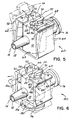
Fig. 5 is a perspective view of a second embodiment of a sample site in accordance with the principles of the present invention; -
Fig. 6 is a perspective view of a third embodiment of a sample site principles of the present invention; and -
Fig. 7 is a diagrammatic view of an exemplary, closed blood sampling system incorporating a sample site of the present invention. - With reference to
Figs. 1-4 , there is shown oneembodiment 10 of a sample site.Sample site 10 is defined by acylindrical housing 12 having aliquid path 14 extending therein. At opposite ends ofpath 14 are femaleluer connector port 16 andmale taper port 18 for connection with tubing or the like, such as for fluid communication with a patient's circulatory system (seeFig. 7 ).Housing 12 includes a needlelessconnector access port 20 betweenports exterior wall 22 ofhousing 12.Wall 22 includes anaperture 24 through which is to be received the tip or taper 26 of amale luer connector 28 for fluid communication withliquid path 14. Aperture 24 is sized to closely surroundtaper 26 when received therethrough. - A valve assembly is provided at
aperture 24 and withinrecess 30 ofhousing 12 betweentop wall 22 andliquid path 14 by frustro-conical actuatingmember 32 fixedly positioned withinhousing 12 and aseal member 38. Actuatingmember 32 includes alumen 34 therethrough transverse to and in fluid communication withliquid path 14.Lumen 34 is aimed at and sealed-off by normally closedchannel 36 ofdiaphragm 37 ofresilient seal member 38 positioned overactuator member 32.Seal member 38 includes tubular shapedhub 42 extending below sealupper surface 40 and with frustro-conical biassing portion 47 ofhub 42 seated over actuatingmember 32. Thetop surface 40 ofseal member 38 is generally flushtop wall 22 when it is closed against oradjacent aperture 24. In this regard, the thickness ofwall 22adjacent aperture 24 is relatively thin in comparison to the length of the maleluer connector tip 26 so as not to define a reservoir wallrelative tip 26.Exterior wall 22 may be about 0.035-0.040 inches (0.9-1.0 mm) thick such that a wipe (not shown) passed acrosswall 22 will easily disinfectwall 22 andsurface 40 without creating a well or reservoir for contaminants or bacteria to accumulate out of reach of the wipe as it passes acrosstop wall 22. Alternatively,surface 40 may protrude fromaperture 24. Thus, it will be appreciated thatupper surface 40 ofseal member 38 may be considered generally flushtop wall 22 in the closed position inasmuch as the surface of the valve assembly is readily accessible to be wiped with disinfectant by wiping acrosstop wall 22 from one side to the other. - As generally described in aforesaid
U.S. Patent No. 4,874,377 , under pressure from malelumen connector taper 26 againstupper surface 40,seal member 38 deflects towardliquid path 14 and driveshub 42 against the conical surface ofprojection 32. Ashub 42 rides overprojection 32,channel 36 is caused to open revealinglumen 34 for fluid communication viatip 26 betweenliquid path 14 and an external fluidic system coupled toconnector 28 such as asyringe 44 or tubing (not shown). Thus as can be seen in the figures, the outer wall 45A ofseal member 38 is in contact withhousing 12 and the inner wall 45B thereof defines a passage 45C for fluid to pass betweenlumen 34 andtaper 26. Whenmale luer connector 28 is removed, the resiliency ofseal member 38 andbiassing portion 47 urges channel 36 closed and also causeshub 42 to ride up frustro-conical actuating member 32 and resealaperture 36 withouter surface 40 againadjacent aperture 24 and generally flushtop wall 22. - To secure
male luer connector 28 to samplesite 10 while not otherwise obstructing wiping access to disinfect the exposedouter surface 40 ofseal member 38 inaperture 24 and adjacent portions ofexternal wall 22, a split luer arrangement is provided. To this end, extending upwardly and away fromtop wall 22 are a pair offlanged arms Arms top wall 22 at spaced apart locationsadjacent aperture 24 such that the arcuateinner surfaces 50 of the arms define an imaginary cylinder 52 (shown in phantom line inFig. 2 ) corresponding to the inner surface of a female luer connector cylinder. Similarly,flanges 54 ofarms Fig. 2 ) corresponding to the threading flange of a female luer connector onto which may be threadably received rotatable threadedcuff 58 of a maleluer lock connector 28, as shown inFig. 4 .Arms - In the embodiment shown in
Figs. 1-4 ,inner surface 50 andflange 54 of eacharm tip 26 and lockingconnector 28 in place, respectively, while leavingaccess port 20 otherwise generally unobstructed. Thus, a clinician (not shown) may readily disinfectaccess port 20 andflange arms top wall 22 such as in the direction fromport 16 to port 18 with a disinfectant material such as with an alcohol wipe to disinfect the area aboutaperture 24. As a consequence, the needless sample site of the present invention eliminates the need to use needles with their attendant risks, while greatly reducing the risk of contamination and bacterial growth normally of great concern with prior needleless sample sites. - An
alternative embodiment 60 of a sample site is shown inFig. 5 .Sample site 60 is substantially similar tosample site 10 with the exception of the provision of a modified split luer connector. In the sample site ofembodiment 60, the entire surface oftop wall 22 may be completely freed from obstruction by placing the split luer in an inoperative position. To this end, the split luer ofembodiment 60 is provided by a pair ofhinge arms bottom wall 65 ofhousing 12 and defining at their extremities a pair of female luer connector portions orflanged arms Hinge arms Fig. 5 witharms housing 12 so as to expose the entirety oftop wall 22 and seal member outer surface 40 (as well as theinner walls 70 ofarms 66, 68) to be easily and readily wiped clean for purposes of disinfection. -
Hinge arms flanged arms arms luer connector portions Fig. 5 to provide the female luer connector function for receiving amale luer connector 28 as in the case ofconnector portions sample site 10. Whenmale luer connector 28 is removed, hingearms inner wall 70 andflange 74 of eachflanged arm - A yet further
alternative embodiment 80 is shown inFig. 6 .Sample site 80 is substantially similar tosample site 60 with the exception of the mechanism for moving femaleluer connector portions frame member 82 is slidably supported on anannular extension 84 attached tobottom 65 ofhousing 12. Attached to framemember 82 are a pair ofhinge arms flanged arms Hinge arms side wall 94 ofhousing 12, such that withframe member 82 slid against bottom 65,shelves top wall 22 to positionflanged arms adjacent aperture 24 to provide the female luer connector function. To disinfect the access port,frame member 82 is slid away from bottom 65 towardflange wall 96 ofannular extension 84. As the frame member is thus moved,top wall 22 andshelves arms housing 12 and away fromaperture 24 allowingflanged arms housing side wall 94 into the inoperative position completely exposingaccess port 20 for disinfecting such as by wiping a disinfectant material thereacross.Hinge arms frame member 82 by finger pressure thereagainst in the direction desired to slideframe member 82. As shown inFig. 6 , hingearms parallel lumen 34 and transverseliquid path 14. The hinge arms could alternatively be mounted to slide parallelliquid path 14 andtransverse lumen 34. - By virtue of the foregoing, there is provided a split luer arrangement to simulate a female luer connector, but without the reservoir which would otherwise impede ready access to access
port 20 includingsurface 40 ofseal member 38 and the adjacent annular portion oftop wall 22 completely surrounding exposedsurface 40 for disinfecting thereof, to reduce the likelihood that contamination of bacterial growth might occur. Althoughhousing 12 has been shown as a T-connection, the access port and split luer combination of the present invention may be provided in other types of sample sites. Thus, the liquid path withinhousing 12 may be coaxial withlumen 34 rather than transverse thereto and may have only one ofports ports ports - Use of the
sample site blood sampling system 150 as shown inFig. 7 .System 150 includes acatheter 152 for insertion into a patient's blood vessel and connected in a series viatubing 154 to abag 156 of saline solution.Bag 156 is wrapped in apressure cuff 158 which may be inflated by an inflation squeeze bulb 160 through astopcock 162. The solution flows out ofbag 156 throughconventional drip chamber 164. Aroller clamp 166 may be mounted ontubing 154adjacent drip chamber 164 in order to selectively block the flow of solution frombag 156 toward the patient. Connected immediately downstream ofroller clamp 166 is a shuntedstopcock 168 coupled to awaste collection bag 170. Downstream ofstopcock 168 is aflush device 172,pressure transducer 174, and three-way stopcock 176.Pressure transducer 174 is electrically connected to monitor 178 bycable 180 for monitoring the patient's blood pressure. A transducer of the type disclosed inU.S. Patent No. 4,920,972 may be employed. Operation of the above is described in greater detail in the aforementionedU.S. Patent 5,148,811 . - In use, the sample site is situated between
catheter 152 and three-way stopcock 176 by couplingport 16 tocatheter 152 andport 18 to stopcock 176 to continue the in-line fluid path betweenbag 156 andcatheter 152.Syringe 44 may be connected in fluid communication therewith by firstwiping access port 20 with a disinfectant and then, if they are movable, placing the female luer connector portions of the sample site into the operative position. Themale luer connector 28 is then fitted to accessport 20 by insertingtip 26 thereof between the inner walls of the split luer and into the aperture to deflectseal member 38 and open the valve assembly under pressure oftip 26 to reveallumen 34 and provide a fluid path betweensyringe 44 andliquid path 14 coupled tocatheter 152. Since the male luer connector is of the locking type, thecuff 58 thereof may be rotated onto the flanges of the split luer to maintain the connection. - After injecting or sampling as desired,
syringe 44 is removed by withdrawing maleluer connector tip 26, allowingseal member 38 to reclose. Theaccess port 20 will also be accessible (or made accessible by movement of the female luer connector portions to the inoperative position) to allowaccess port 20 to again be disinfected by wiping thereacross. - By virtue of the foregoing, there is thus provided a needleless connector sample site in which the access port is generally unobstructed to provide wiping access for disinfecting, while eliminating the risk of needle sticks common to needle-based sample sites and to improve sterility and reduce risk of infection otherwise feared from prior needleless connector sample sites.
- It will be appreciated that the sample site may be utilized as an injection site when coupled to the venous side of a patient's circulatory system, as a sample port when connected to the arterial side, or as a link to connect an exterior fluidic system to an otherwise closed fluidic system without opening the closed system, thereby avoiding the possibility of reflux in the closed system. Reference to sample site will thus be appreciated as a reference to any of the above.
Claims (15)
- A medical site (10,60,80) for use with a medical male luer connector having a blunt male tip (26) with a luer taper and a threaded locking cuff (58) about the male luer taper tip, the site (10,60,80) comprising a housing (12), a liquid path (14) extending into the housing, an apertured exterior wall (22) on the housing through which the male luer taper tip enters the housing (12) to make fluid connection to the liquid path, a seal element (38) retained by and within the housing (12), the seal element (38) having an outer surface (40) exposed adjacent the exterior wall aperture (24), and female luer structure (46,48,66,68) connected to the housing (12), characterised in that the female luer structure (46,48,66,68) comprises female luer locking connector structure (54,74) which extends in a radially outward direction with respect to the aperture (24), the female luer locking connector structure (54, 74) defining a thread plane onto which the threaded locking cuff (58) may be threaded to hold the male luer taper tip (26) within the aperture (24), and in that the female luer structure (46,48,66,68) is connected to the housing (12) and disposed with respect to the aperture (24) in a manner allowing aseptic wiping across the outer surface (40) of the seal element (38) and adjacent portions of the housing (12), the outer surface (40) of the seal element (38) being generally such with the exterior wall aperature (24).
- A medical site as claimed in Claim 1 wherein the female luer structure (46,48,66,68) comprises female luer connector portions (46,48,66,68) formed on the housing.
- A medical site as claimed in Claim 2 wherein the female luer connector portions (46,48,66,68) define 30% of a complete circumference of the thread plane.
- A medical site as claimed in any one of Claims 2 and 3 wherein the female luer connector portions (46,48,66,68) are rigidly connected to the housing (12).
- A medical site as claimed in any one of Claims 2 to 4 wherein the female luer connector portions (46,48,66,68) are connected for movement relative to the housing (12) between an operative position and an inoperative position.
- A medical site as claimed in any one of Claims 2 to 5 wherein the female luer connector portions (46,48,66,68) are elevated relative to the aperture (24) and the exposed outer surface (40).
- A medical site as claimed in any one of Claims 2 to 6 wherein the female luer connector portions are defined by a pair of oppositely disposed lugs (46,48,66,68).
- A medical site as claimed in Claim 1 wherein the female luer structure is disposed below the aperture (24) and the exposed outer surface (40).
- A medical site as claimed in Claim 8 wherein the female luer structure is defined by a pair of oppositely disposed lugs (66,68).
- A medical site as claimed in any preceding Claim in which the seal member (38) includes a diaphragm (37) which presents the outer surface (40), the diaphragm (37) including a channel (36) which may be opened under pressure from the luer taper (26).
- A medical site as claimed in Claim 10 further including a resilient biasing portion (47) behind the diaphragm (37) and extending toward the channel (36) to normally bias the channel closed.
- A medical site as claimed in Claim 11 wherein the seal member (38) includes a tubular portion (42) connected to the diaphragm (37) and wherein the tubular portion (42) carries the biasing portion (47).
- A medical site as claimed in any preceding Claim wherein the seal member (38) includes an outer wall (45A) in contact with the housing (12) and an inner wall (45B) defining a passage (45C) for receiving fluid within a path extending through the luer taper (26).
- A medical site as claimed in any preceding Claim in which the outer surface (40) of the seal member (38) is flat.
- A medical site as claimed in any preceding Claim in which the outer surface (40) of the seal member (38) protrudes from the aperture (24).
Applications Claiming Priority (3)
| Application Number | Priority Date | Filing Date | Title |
|---|---|---|---|
| US58428690A | 1990-09-18 | 1990-09-18 | |
| US584286 | 1990-09-18 | ||
| EP91920317A EP0549730B1 (en) | 1990-09-18 | 1991-09-12 | Needleless connector sample site |
Related Parent Applications (2)
| Application Number | Title | Priority Date | Filing Date |
|---|---|---|---|
| EP91920317A Division EP0549730B1 (en) | 1990-09-18 | 1991-09-12 | Needleless connector sample site |
| EP91920317.4 Division | 1991-09-12 |
Publications (2)
| Publication Number | Publication Date |
|---|---|
| EP0653221A1 EP0653221A1 (en) | 1995-05-17 |
| EP0653221B1 true EP0653221B1 (en) | 2008-10-29 |
Family
ID=24336691
Family Applications (2)
| Application Number | Title | Priority Date | Filing Date |
|---|---|---|---|
| EP91920317A Expired - Lifetime EP0549730B1 (en) | 1990-09-18 | 1991-09-12 | Needleless connector sample site |
| EP94203665A Expired - Lifetime EP0653221B1 (en) | 1990-09-18 | 1991-09-12 | Needleless connector medical site |
Family Applications Before (1)
| Application Number | Title | Priority Date | Filing Date |
|---|---|---|---|
| EP91920317A Expired - Lifetime EP0549730B1 (en) | 1990-09-18 | 1991-09-12 | Needleless connector sample site |
Country Status (7)
| Country | Link |
|---|---|
| EP (2) | EP0549730B1 (en) |
| JP (1) | JPH06500941A (en) |
| AT (2) | ATE125454T1 (en) |
| AU (1) | AU8901891A (en) |
| CA (1) | CA2089750A1 (en) |
| DE (2) | DE69133607D1 (en) |
| WO (1) | WO1992004936A1 (en) |
Families Citing this family (13)
| Publication number | Priority date | Publication date | Assignee | Title |
|---|---|---|---|---|
| US5251873B1 (en) * | 1992-06-04 | 1995-05-02 | Vernay Laboratories | Medical coupling site. |
| US5501426A (en) * | 1992-06-04 | 1996-03-26 | Vernay Laboratories, Inc. | Medical coupling site valve body |
| US5533708A (en) * | 1992-06-04 | 1996-07-09 | Vernay Laboratories, Inc. | Medical coupling site valve body |
| US5242393A (en) * | 1992-06-18 | 1993-09-07 | Becton, Dickinson And Company | Valved blunt cannula injection site |
| US5300034A (en) * | 1992-07-29 | 1994-04-05 | Minnesota Mining And Manufacturing Company | Iv injection site for the reception of a blunt cannula |
| AU6087394A (en) * | 1993-01-13 | 1994-08-15 | Medex, Inc. | Needleless sample set |
| US6068011A (en) * | 1993-10-13 | 2000-05-30 | Paradis; Joseph R. | Control of fluid flow |
| US5470319A (en) | 1994-06-20 | 1995-11-28 | Critical Device Corporation | Needleless injection site |
| US5814024A (en) * | 1996-11-27 | 1998-09-29 | Elcam Plastics | Needleless valve |
| US5807348A (en) * | 1996-11-27 | 1998-09-15 | Elcam Plastics | Needleless valve |
| US5957898A (en) | 1997-05-20 | 1999-09-28 | Baxter International Inc. | Needleless connector |
| US6908459B2 (en) | 2001-12-07 | 2005-06-21 | Becton, Dickinson And Company | Needleless luer access connector |
| US8197452B2 (en) * | 2006-07-28 | 2012-06-12 | Becton, Dickinson And Company | Vascular access device non-adhering surfaces |
Family Cites Families (5)
| Publication number | Priority date | Publication date | Assignee | Title |
|---|---|---|---|---|
| DE3303718C1 (en) * | 1983-02-04 | 1984-10-04 | B. Braun Melsungen Ag, 3508 Melsungen | Injection valve for puncture devices or infusion devices |
| DE3732515A1 (en) * | 1987-09-26 | 1989-04-06 | Joka Kathetertechnik Gmbh | DEVICE FOR INJECTING AND / OR REMOVING LIQUIDS |
| DE68927896T2 (en) * | 1988-01-25 | 1997-10-23 | Baxter Int | Pre-slit injection site and injection cannula |
| US4874377A (en) * | 1988-05-26 | 1989-10-17 | Davis Newgard Revocable Family Living Trust | Self-occluding intravascular cannula assembly |
| US5006114A (en) * | 1990-04-20 | 1991-04-09 | Rogers Bobby E | Medical valve assembly |
-
1991
- 1991-09-12 AT AT91920317T patent/ATE125454T1/en not_active IP Right Cessation
- 1991-09-12 EP EP91920317A patent/EP0549730B1/en not_active Expired - Lifetime
- 1991-09-12 AT AT94203665T patent/ATE412444T1/en not_active IP Right Cessation
- 1991-09-12 CA CA002089750A patent/CA2089750A1/en not_active Abandoned
- 1991-09-12 AU AU89018/91A patent/AU8901891A/en not_active Abandoned
- 1991-09-12 DE DE69133607T patent/DE69133607D1/en not_active Expired - Lifetime
- 1991-09-12 JP JP3518439A patent/JPH06500941A/en active Pending
- 1991-09-12 DE DE69111610T patent/DE69111610D1/en not_active Expired - Lifetime
- 1991-09-12 WO PCT/US1991/006604 patent/WO1992004936A1/en not_active Ceased
- 1991-09-12 EP EP94203665A patent/EP0653221B1/en not_active Expired - Lifetime
Also Published As
| Publication number | Publication date |
|---|---|
| JPH06500941A (en) | 1994-01-27 |
| DE69111610D1 (en) | 1995-08-31 |
| ATE125454T1 (en) | 1995-08-15 |
| ATE412444T1 (en) | 2008-11-15 |
| EP0549730A1 (en) | 1993-07-07 |
| DE69133607D1 (en) | 2008-12-11 |
| CA2089750A1 (en) | 1992-03-19 |
| AU8901891A (en) | 1992-04-15 |
| EP0549730B1 (en) | 1995-07-26 |
| WO1992004936A1 (en) | 1992-04-02 |
| EP0653221A1 (en) | 1995-05-17 |
Similar Documents
| Publication | Publication Date | Title |
|---|---|---|
| US5203775A (en) | Needleless connector sample site | |
| US20230241313A1 (en) | Infusion and blood collection device | |
| US4838855A (en) | Blood aspiration assembly and method | |
| US6793651B1 (en) | Urinary catheter system with a releasable connector | |
| US5188607A (en) | Valve catheter connector assembly | |
| CA2346468C (en) | Swabbable needleless low reflux injection port system | |
| US5203771A (en) | Arterial/venous fluid transfer system | |
| EP0549730B1 (en) | Needleless connector sample site | |
| AU2005284698B2 (en) | Needle free blood collection device with male connector valve | |
| US5417673A (en) | Whole blood sample needleless sample site | |
| JPS62167571A (en) | Liquid sampling or injecting apparatus | |
| US20010039403A1 (en) | Positive flow generator for indwelling medical fluid systems | |
| JPH05200098A (en) | Closed system connector assembly | |
| CA2200526A1 (en) | Valved prn adapter for medical access devices | |
| JPH0425814B2 (en) | ||
| WO1995015194A1 (en) | Slit septum needleless site with check valve | |
| US5827238A (en) | Roller clamp-connector assembly | |
| KR100517199B1 (en) | Vein resin needle set for one time use | |
| WO2015117126A1 (en) | Medical valve | |
| CN115103697A (en) | External terminal device and connection method thereof to flow line |
Legal Events
| Date | Code | Title | Description |
|---|---|---|---|
| PUAI | Public reference made under article 153(3) epc to a published international application that has entered the european phase |
Free format text: ORIGINAL CODE: 0009012 |
|
| 17P | Request for examination filed |
Effective date: 19941216 |
|
| AC | Divisional application: reference to earlier application |
Ref document number: 549730 Country of ref document: EP |
|
| AK | Designated contracting states |
Kind code of ref document: A1 Designated state(s): AT BE CH DE DK ES FR GB GR IT LI LU NL SE |
|
| 17Q | First examination report despatched |
Effective date: 19981210 |
|
| RAP1 | Party data changed (applicant data changed or rights of an application transferred) |
Owner name: MEDEX, INC. |
|
| RIC1 | Information provided on ipc code assigned before grant |
Ipc: A61M 39/10 20060101ALI20070627BHEP Ipc: A61M 39/02 20060101AFI20070627BHEP |
|
| GRAP | Despatch of communication of intention to grant a patent |
Free format text: ORIGINAL CODE: EPIDOSNIGR1 |
|
| GRAS | Grant fee paid |
Free format text: ORIGINAL CODE: EPIDOSNIGR3 |
|
| GRAA | (expected) grant |
Free format text: ORIGINAL CODE: 0009210 |
|
| AC | Divisional application: reference to earlier application |
Ref document number: 0549730 Country of ref document: EP Kind code of ref document: P |
|
| AK | Designated contracting states |
Kind code of ref document: B1 Designated state(s): AT BE CH DE DK ES FR GB GR IT LI LU NL SE |
|
| REG | Reference to a national code |
Ref country code: GB Ref legal event code: FG4D |
|
| REG | Reference to a national code |
Ref country code: CH Ref legal event code: EP |
|
| REF | Corresponds to: |
Ref document number: 69133607 Country of ref document: DE Date of ref document: 20081211 Kind code of ref document: P |
|
| RAP2 | Party data changed (patent owner data changed or rights of a patent transferred) |
Owner name: SMITHS MEDICAL ASD, INC. |
|
| NLV1 | Nl: lapsed or annulled due to failure to fulfill the requirements of art. 29p and 29m of the patents act | ||
| PG25 | Lapsed in a contracting state [announced via postgrant information from national office to epo] |
Ref country code: ES Free format text: LAPSE BECAUSE OF FAILURE TO SUBMIT A TRANSLATION OF THE DESCRIPTION OR TO PAY THE FEE WITHIN THE PRESCRIBED TIME-LIMIT Effective date: 20090209 Ref country code: AT Free format text: LAPSE BECAUSE OF FAILURE TO SUBMIT A TRANSLATION OF THE DESCRIPTION OR TO PAY THE FEE WITHIN THE PRESCRIBED TIME-LIMIT Effective date: 20081029 |
|
| PG25 | Lapsed in a contracting state [announced via postgrant information from national office to epo] |
Ref country code: NL Free format text: LAPSE BECAUSE OF FAILURE TO SUBMIT A TRANSLATION OF THE DESCRIPTION OR TO PAY THE FEE WITHIN THE PRESCRIBED TIME-LIMIT Effective date: 20081029 |
|
| PG25 | Lapsed in a contracting state [announced via postgrant information from national office to epo] |
Ref country code: DK Free format text: LAPSE BECAUSE OF FAILURE TO SUBMIT A TRANSLATION OF THE DESCRIPTION OR TO PAY THE FEE WITHIN THE PRESCRIBED TIME-LIMIT Effective date: 20081029 Ref country code: BE Free format text: LAPSE BECAUSE OF FAILURE TO SUBMIT A TRANSLATION OF THE DESCRIPTION OR TO PAY THE FEE WITHIN THE PRESCRIBED TIME-LIMIT Effective date: 20081029 |
|
| PG25 | Lapsed in a contracting state [announced via postgrant information from national office to epo] |
Ref country code: SE Free format text: LAPSE BECAUSE OF FAILURE TO SUBMIT A TRANSLATION OF THE DESCRIPTION OR TO PAY THE FEE WITHIN THE PRESCRIBED TIME-LIMIT Effective date: 20090129 |
|
| PLBE | No opposition filed within time limit |
Free format text: ORIGINAL CODE: 0009261 |
|
| STAA | Information on the status of an ep patent application or granted ep patent |
Free format text: STATUS: NO OPPOSITION FILED WITHIN TIME LIMIT |
|
| 26N | No opposition filed |
Effective date: 20090730 |
|
| REG | Reference to a national code |
Ref country code: CH Ref legal event code: PL |
|
| PG25 | Lapsed in a contracting state [announced via postgrant information from national office to epo] |
Ref country code: LI Free format text: LAPSE BECAUSE OF NON-PAYMENT OF DUE FEES Effective date: 20090930 Ref country code: GR Free format text: LAPSE BECAUSE OF FAILURE TO SUBMIT A TRANSLATION OF THE DESCRIPTION OR TO PAY THE FEE WITHIN THE PRESCRIBED TIME-LIMIT Effective date: 20090130 Ref country code: CH Free format text: LAPSE BECAUSE OF NON-PAYMENT OF DUE FEES Effective date: 20090930 |
|
| PGFP | Annual fee paid to national office [announced via postgrant information from national office to epo] |
Ref country code: IT Payment date: 20100918 Year of fee payment: 20 Ref country code: FR Payment date: 20100921 Year of fee payment: 20 |
|
| PGFP | Annual fee paid to national office [announced via postgrant information from national office to epo] |
Ref country code: GB Payment date: 20100908 Year of fee payment: 20 |
|
| PGFP | Annual fee paid to national office [announced via postgrant information from national office to epo] |
Ref country code: DE Payment date: 20100908 Year of fee payment: 20 |
|
| PG25 | Lapsed in a contracting state [announced via postgrant information from national office to epo] |
Ref country code: LU Free format text: LAPSE BECAUSE OF NON-PAYMENT OF DUE FEES Effective date: 20090912 |
|
| REG | Reference to a national code |
Ref country code: DE Ref legal event code: R071 Ref document number: 69133607 Country of ref document: DE |
|
| REG | Reference to a national code |
Ref country code: DE Ref legal event code: R071 Ref document number: 69133607 Country of ref document: DE |
|
| REG | Reference to a national code |
Ref country code: GB Ref legal event code: PE20 Expiry date: 20110911 |
|
| PG25 | Lapsed in a contracting state [announced via postgrant information from national office to epo] |
Ref country code: GB Free format text: LAPSE BECAUSE OF EXPIRATION OF PROTECTION Effective date: 20110911 |
|
| PG25 | Lapsed in a contracting state [announced via postgrant information from national office to epo] |
Ref country code: DE Free format text: LAPSE BECAUSE OF EXPIRATION OF PROTECTION Effective date: 20110913 |