EP0651098A2 - Method and system for removing odor from plumbing units - Google Patents
Method and system for removing odor from plumbing units Download PDFInfo
- Publication number
- EP0651098A2 EP0651098A2 EP94307939A EP94307939A EP0651098A2 EP 0651098 A2 EP0651098 A2 EP 0651098A2 EP 94307939 A EP94307939 A EP 94307939A EP 94307939 A EP94307939 A EP 94307939A EP 0651098 A2 EP0651098 A2 EP 0651098A2
- Authority
- EP
- European Patent Office
- Prior art keywords
- air
- toilet
- water
- unit
- intake port
- Prior art date
- Legal status (The legal status is an assumption and is not a legal conclusion. Google has not performed a legal analysis and makes no representation as to the accuracy of the status listed.)
- Withdrawn
Links
Images

Classifications
-
- E—FIXED CONSTRUCTIONS
- E03—WATER SUPPLY; SEWERAGE
- E03D—WATER-CLOSETS OR URINALS WITH FLUSHING DEVICES; FLUSHING VALVES THEREFOR
- E03D9/00—Sanitary or other accessories for lavatories ; Devices for cleaning or disinfecting the toilet room or the toilet bowl; Devices for eliminating smells
- E03D9/04—Special arrangement or operation of ventilating devices
- E03D9/05—Special arrangement or operation of ventilating devices ventilating the bowl
- E03D9/052—Special arrangement or operation of ventilating devices ventilating the bowl using incorporated fans
Definitions
- the present invention relates to methods and systems for reducing or eliminating odors in a room, particularly those associated with bathroom toilets.
- a system for reducing odors associated with a plumbing unit comprising (a) at least one air intake port disposed in the vicinity of the plumbing unit; (b) air displacement means for inducing air into the at least one air intake port; and (c) a piping system through which the air from the at least one air intake port moves to an exhaust location; characterized in that the exhaust location is in a water trap associated with the plumbing unit.
- a method for reducing odors associated with a plumbing unit coupled to a sewer pipe comprising collecting air containing odors from the vicinity of the plumbing unit and exhausting said air into the downstream portion of a water trap associated with the plumbing unit.
- the air displacement means is an air blower which is preferably external to the toilet, as is the exhaust pipe leading from the air blower to the sewer pipe.
- the system further includes sound muffling means for muffling the sound of exhausted air entering the downstream portion of the water trap of the toilet.
- the present invention successfully addresses the shortcomings of the presently known configurations by providing a system and method for reducing or eliminating toilet odors in a way which does not require the ducting of exhaust air to the outside of the dwelling and which ensures that no odors from the sewer system are able to enter the bathroom.
- the method and system of the present invention involves collecting air, preferably from the vicinity of the toilet, and exhausting the air into the water found in the downstream portion of the water trap commonly found in modern toilets.
- the present invention is of a method and system for removing undesirable odors, most particularly toilet odors and kitchen odors. While the method and system are applicable to any plumbing unit, i.e., sink, toilet, irrigation drain, from the area of which it is desired to remove odor-carrying air, they are described hereinbelow with regard to toilets for ease and convenience of description.
- the system When applying the system to toilets, the system can be retrofitted onto an existing toilet but is preferably installed on new toilets by the original manufacturer.
- the toilet bowl can be modified to include the system of the invention as an integral part thereof, or the existing toilet bowl or fresh water feed pipe can be cut and the system of the invention screwed in place therein.
- FIG. 1 illustrates a system according to one embodiment of the present invention.
- Toilet 10 typically includes a base 12 which is permanently connected to the floor, a toilet bowl 14 , a toilet seat 16 and a toilet seat cover 18 .
- Leaving toilet 10 is a sewer pipe 20 which leads the contents of the toilet bowl 14 into the sewer system.
- Entering toilet 10 is a fresh water line 22 which is used for flushing.
- modern toilets such as the one shown in Figure 1, include a water trap.
- the water at the bottom of toilet bowl 14 must first rise before falling into sewer pipe 20 .
- the result is the presence, between flushes, of a pool of water, i.e., a water trap 24 at the bottom of toilet bowl 14 .
- the height of water trap 24 is typically determined by the lowest point of the upward kink in sewer pipe 20 .
- water trap 24 is effectively divided by a divider 26 which serves to induce better circulation during flushing.
- water trap 24 may be considered to be effectively divided into two portions -- an upstream portion and a downstream portion, based on whether gas released in water trap 24 will leave the water into toilet bowl 14 or into sewer pipe 20, respectively.
- the upstream portion of water trap 24 is considered to be all the water located to the right (or forward) of a vertical plane touching the right-most point of divider 26
- all the water to the left (or backward) of the vertical plane touching the right-most point of divider 26 is considered to be the downstream portion of water trap 24 .
- a system according to the present invention includes at least one air intake port. Preferably, several air intake ports are used. Most preferably, at least some of the air intake ports are located on, in, or in the vicinity of toilet 10 .
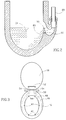
- FIG. 3 Shown in Figure 3 is one of many possible arrangements of air intake ports. Featured are a pair of front intake ports 40 , a pair of intermediate ports 42 and a pair of rear ports 44 mounted on toilet seat 16 . Also shown (in broken lines) are the corresponding take-up pipes 46 , 48 and 50 which run through or immediately adjacent to toilet seat 16 and which are used to convey the collected air to the blower. Preferably, toilet seat 16 is seated on a seal (not shown) which seals any gaps which would otherwise be present between seat 16 and toilet bowl 14 and which would otherwise tend to allow air to escape from toilet bowl 14 .
- An additional cover intake port 52 with its dedicated take-up pipes 54 is included at the lower portion of toilet seat cover 18 and is intended to capture any air which might escape capture by rear air intake ports 44 .
- the air intake port can be in the toilet bowl itself, as described in detail hereinbelow.
- a system according to the present invention includes suitable air displacement means for inducing air into the air intake ports and through the take-up piping.
- the air displacement means includes a suitable air blower 60 , preferably a blower which operates quietly.
- air blower 60 is located outside of toilet 10 so as to avoid possible contact of the electrical components of air blower 60 with moisture associated with toilet 10 .
- air blower 60 is electrically driven with energy being supplied from the household electrical system.
- Air blower 60 is preferably mounted either onto a suitable portion of the outside of toilet 10 or sewer pipe 20 or is mounted (as shown in Figure 1) to the wall 62 with a suitable mounting member 64 .
- a system according to the present invention includes a piping system through which the air collected by the various air intake ports moves to an exhaust location.
- a system according to the present invention is configured so that the take-up pipes from the various air intake ports (for example, see Figure 3) come together to form a single take-up pipe 66 which is connected to the suction side of air blower 60 .
- the exhaust side of air blower 60 is connected to an exhaust pipe 68 which leads the collected air to the proper exhaust location, as described below.
- exhaust pipe 68 runs on the outside of toilet bowl 14 , so as not to interfere with the normal operations of toilet 10.
- Exhaust pipe 68 may be clamped or otherwise attached to sewer pipe 20 or to some other suitable structure using various clamps 70 or outer mechanisms.
- the system and method according to the present invention are characterized in that the exhaust location is not the outside of the dwelling or in a location from which the odors can return into the area from which they have been removed. Rather, the exhaust location is a water trap which acts as a one-way valve for passage of odors.
- the exhaust location is the downstream portion of water trap 24 , as that location was described above.
- the exhaust location is at the side of the downstream portion of water trap 24 of toilet 10 , as shown in Figure 1.
- the location of the exhaust in water trap 24 rather than directly in the air-filled portion of sewer pipe 20 is critical in that the presence of water around the exhaust ensures that no odors from the sewer system will be able to enter the exhaust pipe and enter the bathroom.
- the release of the air in the downstream portion of water trap 24 ensures that any odors which might escape from the water will enter the air-filled sewer pipe 20 rather than the air space above water trap 24 in toilet bowl 14 from where the odors could escape into the bathroom.
- one result of releasing air directly into the water is that the release may be accompanied by the generation of bubbling sounds which some users might find objectionable.
- Another disadvantage is that bubbling might lead to the premature loss of water to the sewer line. It is thus preferable to include a suitable muffling system which will tend to reduce or eliminate the bubbling sounds in question and which will preferably also prevent the premature escape of water to the sewer. Various ways of accomplishing this may be envisioned.
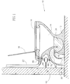
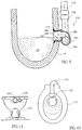
- Figure 2 is a cross-sectional back view of the downstream portion of water trap 24 specifically showing exhaust pipe 68 and its entrance into water trap 24 .
- the passage through which air enters water trap 24 features an upward turn of approximately 180° so that air is exhausted in a substantially vertical orientation.
- the entrance region 92 which could be part of either toilet 10 (as in Figure 2) or exhaust pipe 68 , includes a barrier 90 which directs the incoming air upward into the downstream portion of water trap 24 .
- the top of barrier 90 is flush with, or extends slightly above, the water level.
- barrier 90 extends in a direction toward the upstream portion of water trap 24 so as to prevent water from the downstream portion of water trap 24 from splashing into sewer pipe 20 and thereby lowering the water level in toilet bowl 14 .
- Barrier 90 includes a small opening 80 therethrough which serves to fill the entrance region with water and form a proper water seal so as to prevent sewer odors from entering sewer pipe 68 .
- the exhaust of air would be as follows.
- air blower 60 When air blower 60 is first activated, air would be forced through exhaust pipe 68 .
- the first flow of air would displace water present in the entrance region 92 upwards, in effect releasing a bubble near the top portion of barrier 90 .
- the magnitude of the air flow and the size of entrance region 92 are preferably such that once the initial air breaks through to the surface, flow of air to the surface is continuous and no sound-producing bubbles are generated.
- the trickle of water which enters entrance region 92 through opening 80 will be pulled upward with the air.
- a system according to the present invention may be activated by a manually operated switch or could be activated automatically in any of a number of ways.
- an automatic switch could be installed so that the blower is activated whenever toilet seat cover 18 is raised or whenever toilet seat 16 is lowered.
- activation may occur through the use of sensors, such as visual sensors which detect the presence of a user or weight sensors which sense when a user is sitting on toilet seat 16 .
- a separate unit for receiving the collected air and for releasing the air into the sewer pipe downstream of the water trap is provided.
- This embodiment is suitable both for retrofit applications on existing toilet equipment wherein a hole is drilled, and for use on a new toilet which is formed with an aperture in the toilet bowl.
- a standard toilet bowl 14' with an aperture 15 therein for receiving an odor-removing unit 170 .
- Odor-removing unit 170 is sealed in aperture 15 as by an O-ring 172 .
- Odor-removing unit 170 includes an air intake pipe 174 extending, in this embodiment, from an air intake port 176 .
- Air displacement means 178 preferably an air blower, is disposed in air intake pipe 174 which ends in a hooked portion 180 .
- Hooked portion 180 has an inlet 182 into a water-bearing cup element 184 and an outlet 186 into an exhaust pipe (not shown), preferably in the sewer line. According to a preferred embodiment of the invention, hooked portion 180 is twisted such that outlet 186 is perpendicular to inlet 182.
- Cup element 184 includes a shield 188 which extends to or slightly above the water level in toilet bowl 14' .
- a small diameter water inlet 190 is provided in shield 188 so that water can flow from water trap 24' into cup element 184 .
- shield 188 is higher than the highest point of inlet 182 so that odors from the sewer system cannot enter toilet bowl 24' .
- an aperture for the air intake port is integrally formed with the toilet bowl during manufacture.
- a toilet bowl is shown in Fig. 10.
- air intake port 176' is formed by making a groove in the rim of the toilet bowl 177' which is covered, as with a plastic cover, to form pipe 174' carrying the air to the odor removing unit.
- Air intake port 176' may be formed at the end of the bowl, as illustrated, or on the side thereof.
- a separate aperture 200 is formed in toilet bowl 202 to form an air intake port adjacent the fresh water inlet aperture 204 .
- This embodiment has the added advantage that no water will be accidentally carried to the blower with the odor-carrying air.
- a separate odor removing unit may be mounted equally effectively in a location other than the toilet bowl. This permits minimal modification of the existing plumbing unit and is, thus, particularly suitable for retrofitting on existing units.
- One embodiment of such a unit is shown in Figs. 4 and 5.
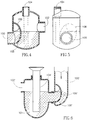
- the odor removing unit is shown in two side views in Figures 4 and 5.
- the unit may be installed at any convenient location, for example, mounted onto the outside of the sewer, and can be made of any convenient material, preferably a suitable plastic. Most preferably, the unit is mounted behind a conventional toilet bowl, coupled to the sewer pipe.
- the unit includes an inlet 100 , which corresponds to exhaust pipe 68 of Figure 1, for bringing odor-containing air into the unit.
- the unit further includes an outlet 102 which exhausts air into sewer pipe 20 ( Figure 1), preferably into a portion of sewer pipe 20 which is downstream of the water trap and air-filled and where sewer pipe 20 is made of a plastic material.
- the unit further includes a fresh water inlet 104 which is preferably connected via a small diameter pipe (not shown) to the fresh water feed line of the toilet at a point downstream of the toilet valve, so that water is introduced into the unit through fresh water inlet 104 during flushing of the toilet.
- Outlet 102 is located so that its lowest point is above the highest point of inlet 100 .
- Inlet 100 is located in the side of the unit and its entrance is provided with a shield 106 which is designed to allow air to enter the unit through the water which fills the bottom portion of the unit and inlet 100 .
- a small hole 108 in shield 106 ( Figure 4) allows water from the main compartment of the unit to flow into the area beyond shield 106 until the water level in this area is the same as that of the water in the main compartment of the unit.
- the unit functions as follows.
- air is pushed through inlet 100 and rises into the air space at the top of the unit.
- the water within shield 106 is pushed outwards together with the air. From there the air exits the unit through outlet 102 directly into the air-filled portion of the sewer pipe downstream of the water trap.
- the blower is turned off, water from the main compartment of the unit seeps through hole 108 into the area beyond shield 108 , thereby reforming the water trap which serves to prevent any odor-carrying air from travelling from the sewer through outlet 102 and through inlet 100 and back into the room.
- a small amount of water flows into the unit to ensure that the water level is at the proper level at all times.
- the odor-carrying air is released into the toilet bowl, which is typically made of a suitable ceramic. It will be appreciated that creating an opening in an existing ceramic toilet bowl may be complicated or expensive.
- the release point is preferably well downstream of the water trap in the portion of the sewer pipe which is typically made of plastic, such as PVC, rather than ceramic. It is generally much easier and less expensive to drill a hole into a plastic pipe.
- FIG. 6 there is shown an alternate embodiment of the invention which is similar to that shown in Fig. 4 but is particularly suited for use in a kitchen sink or other sink in an area from which it is desired to remove odors.
- the air inlet 100' and shield 106' are located outside the siphon 101 of the sink.
- an aperture 103 with screw threads is formed in the conventional siphon 101 of a sink (not shown).
- An odor removing unit according to the invention is screwed onto aperture 103 .
- the unit includes an air inlet 100' and a shield 106' .
- the siphon 101 is coupled to a sewer pipe (not shown) through an outlet 102' .
- Operation of this embodiment is substantially the same as that of Fig. 4.
- Water from the sink fills the siphon 101 and the bottom of the odor removing unit through fresh water inlet 104' .
- a blower in the unit (not shown) is activated and the odor-carrying air is blown into inlet 100' .
- the air pressure forces the water out from shield 106' and the air is free to flow out through siphon 101 and through outlet 102' to the sewer pipe.
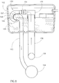
- a unit 110 for receiving and releasing the collected air is inserted into the fresh water feed line 112 of toilet 114 and coupled to sewer pipe 120 .
- fresh water feed line 112 performs two additional functions: sucking air and odors into unit 110 and providing water to a cup element which acts as a one-way valve to prevent odors from returning from the sewer pipe into the toilet.
- Unit 110 includes an inlet 116 and an outlet 118 .
- An arched pipe 122 couples inlet 116 with outlet 118 via an air blower 124 and a water-bearing cup element 126 .
- Pipe 122 ends in a hooked portion 123 from which water can be pushed by air pressure into cup element 126 .
- Most preferably the hooked portion is curved such that the outlet is perpendicular to the longitudinal axis of the inlet.
- Hooked portion 123 is provided with a small fresh water inlet aperture 125 through which water from cup element 126 enters to refill hooked portion 123 .
- Air and odors flowing through hooked portion 123 pass through an outlet pipe 134 into sewer pipe 120 , preferably downstream of the water trap of the toilet (not shown).
- a ball valve 128 is seated in inlet 116 and is retained therein by stop members 130 and 132 .
- a unit 150 for receiving and releasing collected air is disposed inside the fresh water tank 152 .
- Unit 150 includes a air blower 154 which sucks the collected odor-filled air from toilet 156 through a pipe 158 .
- the collected air is pushed by air blower 154 through a pipe 155 , which ends in a hooked portion 177 similar to that in Fig. 7.
- the air is blown through a water-bearing cup element 160 and out through an outlet pipe 162 to sewer pipe 164 .
- Cup element 160 defines a small fresh water inlet aperture 166 for permitting the inflow of water into the cup element to maintain the desired water level.
- a shield 168 depends into cup element 166 , the bottom of shield 168 being lower than the lowest part of inlet 157 to exhaust pipe 162 so as to prevent the return of exhaust gases therethrough. Operation of this embodiment is substantially the same as that of Fig. 7.
- the water trap formed by the hooked portion of the inlet pipe and the cup element acts as a one-way valve for odors, preventing their return from the sewer into the toilet or kitchen. It is a further particular feature of these embodiments that there is virtually no bubbling noise during their operation. This is due to the angled twist and the smooth walls of the hooked portion of the air intake pipe which permit the ready outflow of the water therein upon application of air pressure. Thus, no additional silencing means are required.
- the waste water continues to flow unimpeded through its usual pathway, and without soiling the elements of the system.
Abstract
A system for reducing odors associated with a plumbing unit comprising at least one air intake port (66) disposed in the vicinity of the plumbing unit, air displacement means (60) for inducing air into the at least one air intake port (66), and a piping system through which the air from the at least one air intake port (66) moves to an exhaust location (68), characterized in that the exhaust location (68) is in a water trap associated with the plumbing unit (10).
Description
- The present invention relates to methods and systems for reducing or eliminating odors in a room, particularly those associated with bathroom toilets.
- Considerable efforts have been devoted to reducing or eliminating the odors which are typically associated with toilets. One of the earliest examples of these efforts is the widespread use of a water trap in conventional modern toilets. Thus, the vast majority of toilets are currently designed so that the outlet pipe from the toilet to the sewer system first rises and then falls which ensures that a certain amount of water will always be trapped at the bottom of the toilet bowl. The standing water which constitutes the water trap prevents odors from the sewer line from entering the toilet and the bathroom.
- While the widespread use of water traps is highly effective in preventing odors arising from wastes which have already been flushed into the sewer system, water traps are largely ineffective in reducing or eliminating odors which do not reach the water in the toilet bowl or which rise up from the water prior to flushing. These odors can leave the toilet and pervade the bathroom, which may inconvenience users of the bathroom.
- Various attempts have been made to solve the above-described problem. In common use are various vents which are located at one or more convenient points in the bathroom and which use an air blower to move air from the bathroom and kitchen to the outside of the house. A disadvantage of this system is that it allows the odors to spread throughout the bathroom prior to venting to the outside which does little to aid an immediate user of the toilet. An additional disadvantage is that the use of a vent requires expensive installation since a passageway must be made in an exterior wall of the house and since suitable ducting, which is often unsightly or at least aesthetically displeasing, must be installed.
- To partially overcome these disadvantages, systems have been proposed to provide air intake ports at or near the toilet bowl itself so as to capture the odors before they have a chance to spread throughout the bathroom. The captured odors are then exhausted to the outside of the house. While this represents an advance over the simple bathroom venting system, the problem of expensive and unsightly ducting remains.
- To overcome these disadvantages, it has been proposed to exhaust the captured air into the air-filled portion of the sewer line just downstream of the water trap by tapping the sewer line and connecting thereto the exhaust air line. The difficulty with such a system is that whenever the blower is not operating, it may be possible for odors from the sewer system to enter the exhaust line and thence into the room, effectively bypassing, and reducing the effectiveness of, the water trap which is intended to eliminate precisely this situation. To overcome this disadvantage it may be necessary to equip the system with a suitable one-way valve or other shutoff means, which would add to the cost and complexity of the system and which would degrade its reliability.
- There is thus a widely recognized need for, and it would be highly advantageous to have, a method and system for effectively removing toilet odors without the need for air ducting to the outside of the dwelling and without incurring the risk of introducing sewer odors into the bathroom or kitchen.
- According to the present invention there is provided a system for reducing odors associated with a plumbing unit comprising (a) at least one air intake port disposed in the vicinity of the plumbing unit; (b) air displacement means for inducing air into the at least one air intake port; and (c) a piping system through which the air from the at least one air intake port moves to an exhaust location; characterized in that the exhaust location is in a water trap associated with the plumbing unit.
- Also according to the present invention, there is provided a method for reducing odors associated with a plumbing unit coupled to a sewer pipe comprising collecting air containing odors from the vicinity of the plumbing unit and exhausting said air into the downstream portion of a water trap associated with the plumbing unit.
- According to further features in preferred embodiments of the invention described below, the air displacement means is an air blower which is preferably external to the toilet, as is the exhaust pipe leading from the air blower to the sewer pipe.
- According to still further features in the described preferred embodiments, the system further includes sound muffling means for muffling the sound of exhausted air entering the downstream portion of the water trap of the toilet.
- The present invention successfully addresses the shortcomings of the presently known configurations by providing a system and method for reducing or eliminating toilet odors in a way which does not require the ducting of exhaust air to the outside of the dwelling and which ensures that no odors from the sewer system are able to enter the bathroom.
- More specifically, the method and system of the present invention involves collecting air, preferably from the vicinity of the toilet, and exhausting the air into the water found in the downstream portion of the water trap commonly found in modern toilets.
- The invention is herein described, by way of example only, with reference to the accompanying drawings, wherein:
- FIG. 1 is a schematic side cross sectional view of a typical toilet showing portions of a system according to the present invention;
- FIG. 2 is a cross-sectional back view of the downstream portion of the water trap showing one possible way in which air enters the water in the downstream portion of the water trap;
- FIG. 3 is a top view of a toilet bowl seat and cover, showing one possible arrangement of air intake ports;
- FIG. 4 is a side view of an alternate embodiment of the present invention;
- FIG. 5 is another side view of the embodiment of Figure 4;
- FIG. 6 is a side view of an alternative embodiment of the invention for use in the siphon of a sink;
- Fig. 7 is a schematic sectional view of another alternate embodiment of the present invention;
- Fig. 8 is a schematic sectional view of still another embodiment of the invention;
- Fig. 9 is a side view of a further embodiment of the invention;
- Fig. 10 is a top view of a toilet bowl according to one embodiment of the invention;
- Fig. 11 is a rear view of a toilet bowl according to an alternate embodiment of the invention.
- The present invention is of a method and system for removing undesirable odors, most particularly toilet odors and kitchen odors. While the method and system are applicable to any plumbing unit, i.e., sink, toilet, irrigation drain, from the area of which it is desired to remove odor-carrying air, they are described hereinbelow with regard to toilets for ease and convenience of description.
- When applying the system to toilets, the system can be retrofitted onto an existing toilet but is preferably installed on new toilets by the original manufacturer. According to various embodiments, the toilet bowl can be modified to include the system of the invention as an integral part thereof, or the existing toilet bowl or fresh water feed pipe can be cut and the system of the invention screwed in place therein. The principles and operation of a system according to the present invention may be better understood with reference to the drawings and the accompanying description.
- Referring now to the drawings, Figure 1 illustrates a system according to one embodiment of the present invention. Shown in Figure 1 is a typical
modern toilet 10 which has been slightly modified to accommodate a system according to the present invention.Toilet 10 typically includes abase 12 which is permanently connected to the floor, atoilet bowl 14, atoilet seat 16 and atoilet seat cover 18. Leavingtoilet 10 is asewer pipe 20 which leads the contents of thetoilet bowl 14 into the sewer system. Enteringtoilet 10 is afresh water line 22 which is used for flushing. - As described briefly, modern toilets, such as the one shown in Figure 1, include a water trap. Thus, the water at the bottom of
toilet bowl 14 must first rise before falling intosewer pipe 20. The result is the presence, between flushes, of a pool of water, i.e., awater trap 24 at the bottom oftoilet bowl 14. The height ofwater trap 24 is typically determined by the lowest point of the upward kink insewer pipe 20. Typically,water trap 24 is effectively divided by a divider 26 which serves to induce better circulation during flushing. - For purposes of discussion,
water trap 24 may be considered to be effectively divided into two portions -- an upstream portion and a downstream portion, based on whether gas released inwater trap 24 will leave the water intotoilet bowl 14 or intosewer pipe 20, respectively. Thus, in the example of Figure 1, the upstream portion ofwater trap 24 is considered to be all the water located to the right (or forward) of a vertical plane touching the right-most point of divider 26, while all the water to the left (or backward) of the vertical plane touching the right-most point of divider 26 is considered to be the downstream portion ofwater trap 24. - A system according to the present invention includes at least one air intake port. Preferably, several air intake ports are used. Most preferably, at least some of the air intake ports are located on, in, or in the vicinity of
toilet 10. - Shown in Figure 3 is one of many possible arrangements of air intake ports. Featured are a pair of
front intake ports 40, a pair ofintermediate ports 42 and a pair ofrear ports 44 mounted ontoilet seat 16. Also shown (in broken lines) are the corresponding take-up pipes toilet seat 16 and which are used to convey the collected air to the blower. Preferably,toilet seat 16 is seated on a seal (not shown) which seals any gaps which would otherwise be present betweenseat 16 andtoilet bowl 14 and which would otherwise tend to allow air to escape fromtoilet bowl 14. - An additional
cover intake port 52 with its dedicated take-up pipes 54 is included at the lower portion oftoilet seat cover 18 and is intended to capture any air which might escape capture by rearair intake ports 44. - Alternatively, the air intake port can be in the toilet bowl itself, as described in detail hereinbelow.
- A system according to the present invention includes suitable air displacement means for inducing air into the air intake ports and through the take-up piping. Preferably, the air displacement means includes a
suitable air blower 60, preferably a blower which operates quietly. Preferably,air blower 60 is located outside oftoilet 10 so as to avoid possible contact of the electrical components ofair blower 60 with moisture associated withtoilet 10. Preferably,air blower 60 is electrically driven with energy being supplied from the household electrical system.Air blower 60 is preferably mounted either onto a suitable portion of the outside oftoilet 10 orsewer pipe 20 or is mounted (as shown in Figure 1) to thewall 62 with a suitable mountingmember 64. A system according to the present invention includes a piping system through which the air collected by the various air intake ports moves to an exhaust location. - Preferably, a system according to the present invention is configured so that the take-up pipes from the various air intake ports (for example, see Figure 3) come together to form a single take-up
pipe 66 which is connected to the suction side ofair blower 60. The exhaust side ofair blower 60 is connected to anexhaust pipe 68 which leads the collected air to the proper exhaust location, as described below. Preferably,exhaust pipe 68 runs on the outside oftoilet bowl 14, so as not to interfere with the normal operations oftoilet 10.Exhaust pipe 68 may be clamped or otherwise attached tosewer pipe 20 or to some other suitable structure usingvarious clamps 70 or outer mechanisms. - The system and method according to the present invention are characterized in that the exhaust location is not the outside of the dwelling or in a location from which the odors can return into the area from which they have been removed. Rather, the exhaust location is a water trap which acts as a one-way valve for passage of odors. In the embodiment illustrated in Fig. 1, the exhaust location is the downstream portion of
water trap 24, as that location was described above. Preferably, the exhaust location is at the side of the downstream portion ofwater trap 24 oftoilet 10, as shown in Figure 1. - The location of the exhaust in
water trap 24 rather than directly in the air-filled portion ofsewer pipe 20 is critical in that the presence of water around the exhaust ensures that no odors from the sewer system will be able to enter the exhaust pipe and enter the bathroom. At the same time, the release of the air in the downstream portion ofwater trap 24 ensures that any odors which might escape from the water will enter the air-filledsewer pipe 20 rather than the air space abovewater trap 24 intoilet bowl 14 from where the odors could escape into the bathroom. - In this embodiment, one result of releasing air directly into the water is that the release may be accompanied by the generation of bubbling sounds which some users might find objectionable. Another disadvantage is that bubbling might lead to the premature loss of water to the sewer line. It is thus preferable to include a suitable muffling system which will tend to reduce or eliminate the bubbling sounds in question and which will preferably also prevent the premature escape of water to the sewer. Various ways of accomplishing this may be envisioned.
- One example of a sound muffling technique is shown in Figure 2 which is a cross-sectional back view of the downstream portion of
water trap 24 specifically showingexhaust pipe 68 and its entrance intowater trap 24. As can be seen in Figure 2, the passage through which air enterswater trap 24 features an upward turn of approximately 180° so that air is exhausted in a substantially vertical orientation. Theentrance region 92, which could be part of either toilet 10 (as in Figure 2) orexhaust pipe 68, includes abarrier 90 which directs the incoming air upward into the downstream portion ofwater trap 24. The top ofbarrier 90 is flush with, or extends slightly above, the water level. Preferably, the top portion ofbarrier 90 extends in a direction toward the upstream portion ofwater trap 24 so as to prevent water from the downstream portion ofwater trap 24 from splashing intosewer pipe 20 and thereby lowering the water level intoilet bowl 14.Barrier 90 includes asmall opening 80 therethrough which serves to fill the entrance region with water and form a proper water seal so as to prevent sewer odors from enteringsewer pipe 68. - In operation, the exhaust of air would be as follows. When
air blower 60 is first activated, air would be forced throughexhaust pipe 68. The first flow of air would displace water present in theentrance region 92 upwards, in effect releasing a bubble near the top portion ofbarrier 90. The magnitude of the air flow and the size ofentrance region 92 are preferably such that once the initial air breaks through to the surface, flow of air to the surface is continuous and no sound-producing bubbles are generated. The trickle of water which entersentrance region 92 throughopening 80 will be pulled upward with the air. As soon asair blower 60 is deactivated, water enteringentrance region 92 throughopening 80 is no longer being removed and quickly fills upentrance region 92, thereby creating an effective water seal preventing odors from the sewer from enteringexhaust pipe 68. The result of this configuration is a significant reduction in the sound generation while preserving a good seal against sewer odors. - A system according to the present invention may be activated by a manually operated switch or could be activated automatically in any of a number of ways. For example, an automatic switch could be installed so that the blower is activated whenever
toilet seat cover 18 is raised or whenevertoilet seat 16 is lowered. Alternatively, activation may occur through the use of sensors, such as visual sensors which detect the presence of a user or weight sensors which sense when a user is sitting ontoilet seat 16. - In an alternate embodiment of the present invention shown in Fig. 9, a separate unit for receiving the collected air and for releasing the air into the sewer pipe downstream of the water trap is provided. This embodiment is suitable both for retrofit applications on existing toilet equipment wherein a hole is drilled, and for use on a new toilet which is formed with an aperture in the toilet bowl.
- In Fig. 9, there is shown, in cross-section through the downstream portion of the conventional water trap 24', a standard toilet bowl 14' with an aperture 15 therein for receiving an odor-removing
unit 170. Odor-removingunit 170 is sealed in aperture 15 as by an O-ring 172. - Odor-removing
unit 170 includes anair intake pipe 174 extending, in this embodiment, from anair intake port 176. Air displacement means 178, preferably an air blower, is disposed inair intake pipe 174 which ends in a hookedportion 180.Hooked portion 180 has aninlet 182 into a water-bearingcup element 184 and anoutlet 186 into an exhaust pipe (not shown), preferably in the sewer line. According to a preferred embodiment of the invention, hookedportion 180 is twisted such thatoutlet 186 is perpendicular toinlet 182. -
Cup element 184 includes ashield 188 which extends to or slightly above the water level in toilet bowl 14'. A smalldiameter water inlet 190 is provided inshield 188 so that water can flow from water trap 24' intocup element 184. - Operation of this embodiment is as follows. When
blower 178 is activated, air is drawn in throughair intake pipe 174 from the vicinity of the toilet bowl along the path indicated by the arrows. The air is pushed throughinlet 182 intocup element 184. The air pressure is sufficient to push the standing water out ofcup element 184, thus permitting the free passage of odor-carrying air through hookedportion 180 and outoutlet 186 to the sewer pipe. When the toilet is flushed or when theblower 178 ceases to blow,cup element 184 is refilled over the top ofshield 188, the level being maintained viawater inlet 190. - It will be appreciated that
shield 188 is higher than the highest point ofinlet 182 so that odors from the sewer system cannot enter toilet bowl 24'. - According to a preferred embodiment of the invention, an aperture for the air intake port is integrally formed with the toilet bowl during manufacture. One embodiment of such a toilet bowl is shown in Fig. 10. In this embodiment, air intake port 176' is formed by making a groove in the rim of the toilet bowl 177' which is covered, as with a plastic cover, to form pipe 174' carrying the air to the odor removing unit. Air intake port 176' may be formed at the end of the bowl, as illustrated, or on the side thereof.
- According to another embodiment, shown in Fig. 11, a
separate aperture 200 is formed intoilet bowl 202 to form an air intake port adjacent the freshwater inlet aperture 204. This is particularly suitable for mass production. This embodiment has the added advantage that no water will be accidentally carried to the blower with the odor-carrying air. - Alternatively, a separate odor removing unit may be mounted equally effectively in a location other than the toilet bowl. This permits minimal modification of the existing plumbing unit and is, thus, particularly suitable for retrofitting on existing units. One embodiment of such a unit is shown in Figs. 4 and 5.
- The odor removing unit is shown in two side views in Figures 4 and 5. The unit may be installed at any convenient location, for example, mounted onto the outside of the sewer, and can be made of any convenient material, preferably a suitable plastic. Most preferably, the unit is mounted behind a conventional toilet bowl, coupled to the sewer pipe.
- The unit includes an
inlet 100, which corresponds toexhaust pipe 68 of Figure 1, for bringing odor-containing air into the unit. The unit further includes anoutlet 102 which exhausts air into sewer pipe 20 (Figure 1), preferably into a portion ofsewer pipe 20 which is downstream of the water trap and air-filled and wheresewer pipe 20 is made of a plastic material. The unit further includes afresh water inlet 104 which is preferably connected via a small diameter pipe (not shown) to the fresh water feed line of the toilet at a point downstream of the toilet valve, so that water is introduced into the unit throughfresh water inlet 104 during flushing of the toilet. -
Outlet 102 is located so that its lowest point is above the highest point ofinlet 100.Inlet 100 is located in the side of the unit and its entrance is provided with ashield 106 which is designed to allow air to enter the unit through the water which fills the bottom portion of the unit andinlet 100. Asmall hole 108 in shield 106 (Figure 4) allows water from the main compartment of the unit to flow into the area beyondshield 106 until the water level in this area is the same as that of the water in the main compartment of the unit. - In operation the unit functions as follows. When the blower is activated, air is pushed through
inlet 100 and rises into the air space at the top of the unit. In the process, the water withinshield 106 is pushed outwards together with the air. From there the air exits the unit throughoutlet 102 directly into the air-filled portion of the sewer pipe downstream of the water trap. When the blower is turned off, water from the main compartment of the unit seeps throughhole 108 into the area beyondshield 108, thereby reforming the water trap which serves to prevent any odor-carrying air from travelling from the sewer throughoutlet 102 and throughinlet 100 and back into the room. Whenever the toilet is flushed, a small amount of water flows into the unit to ensure that the water level is at the proper level at all times. - In the embodiment of Fig. 1 described above, the odor-carrying air is released into the toilet bowl, which is typically made of a suitable ceramic. It will be appreciated that creating an opening in an existing ceramic toilet bowl may be complicated or expensive. In the embodiment of Fig. 4, on the other hand, the release point is preferably well downstream of the water trap in the portion of the sewer pipe which is typically made of plastic, such as PVC, rather than ceramic. It is generally much easier and less expensive to drill a hole into a plastic pipe.
- Referring now to Fig. 6 there is shown an alternate embodiment of the invention which is similar to that shown in Fig. 4 but is particularly suited for use in a kitchen sink or other sink in an area from which it is desired to remove odors. In this embodiment, the air inlet 100' and shield 106' are located outside the siphon 101 of the sink.
- In this embodiment, an aperture 103 with screw threads is formed in the conventional siphon 101 of a sink (not shown). An odor removing unit according to the invention is screwed onto aperture 103. The unit includes an air inlet 100' and a shield 106'. The siphon 101 is coupled to a sewer pipe (not shown) through an outlet 102'.
- Operation of this embodiment is substantially the same as that of Fig. 4. Water from the sink fills the siphon 101 and the bottom of the odor removing unit through fresh water inlet 104'. When it is desired to remove odors from the area of the sink, including cooking odors and so on from the kitchen, a blower in the unit (not shown) is activated and the odor-carrying air is blown into inlet 100'. The air pressure forces the water out from shield 106' and the air is free to flow out through siphon 101 and through outlet 102' to the sewer pipe.
- Referring now to Fig. 7, there is shown an alternate embodiment of the system of the present invention wherein a
unit 110 for receiving and releasing the collected air is inserted into the freshwater feed line 112 oftoilet 114 and coupled tosewer pipe 120. In this embodiment, freshwater feed line 112 performs two additional functions: sucking air and odors intounit 110 and providing water to a cup element which acts as a one-way valve to prevent odors from returning from the sewer pipe into the toilet. -
Unit 110 includes aninlet 116 and anoutlet 118. Anarched pipe 122couples inlet 116 withoutlet 118 via anair blower 124 and a water-bearingcup element 126.Pipe 122 ends in a hookedportion 123 from which water can be pushed by air pressure intocup element 126. Most preferably the hooked portion is curved such that the outlet is perpendicular to the longitudinal axis of the inlet.Hooked portion 123 is provided with a small freshwater inlet aperture 125 through which water fromcup element 126 enters to refill hookedportion 123. - Air and odors flowing through hooked
portion 123 pass through anoutlet pipe 134 intosewer pipe 120, preferably downstream of the water trap of the toilet (not shown). Aball valve 128 is seated ininlet 116 and is retained therein bystop members - The method of operation of this system is as follows. Odor-carrying air is sucked through
inlet 116 ofair intake pipe 122 and pushed through hookedportion 123 byair blower 124. The air pushes the water out ofhooked portion 123 intocup element 126 and then flows freely throughpipe 134 intosewer pipe 120. As shown,ball valve 128 is seated by gravity againststop member 132 permitting the passage of air therepast. - When the toilet is flushed, fresh water flows through
pipe 112 both totoilet 114 and intoinlet 116 ofpipe 122. The water pressure urgesball valve 128 to seat againststop member 130, thereby preventing passage of water throughpipe 122. At the same time, water flows through a small diameter pipe 136 coupling the freshwater feed pipe 112 withcup element 126 to maintain the desired water level inhooked portion 123. When the flushing water ceases to flow,ball valve 128 returns to the open position againststop member 132, as illustrated. It will be noted that theinner wall 127 ofpipe 122 entends below the inlet topipe 134, thereby preventing the backflow of air therethrough. - Referring now to Fig. 8, there is shown a schematic illustration of yet another embodiment of the present invention for use in a toilet which is particularly aesthetic. In this embodiment, a
unit 150 for receiving and releasing collected air is disposed inside thefresh water tank 152.Unit 150 includes aair blower 154 which sucks the collected odor-filled air fromtoilet 156 through apipe 158. The collected air is pushed byair blower 154 through apipe 155, which ends in a hookedportion 177 similar to that in Fig. 7. The air is blown through a water-bearingcup element 160 and out through anoutlet pipe 162 tosewer pipe 164.Cup element 160 defines a small freshwater inlet aperture 166 for permitting the inflow of water into the cup element to maintain the desired water level. Ashield 168 depends intocup element 166, the bottom ofshield 168 being lower than the lowest part ofinlet 157 toexhaust pipe 162 so as to prevent the return of exhaust gases therethrough. Operation of this embodiment is substantially the same as that of Fig. 7. - It is a particular feature of the embodiments of Figs. 4 through 9 that the water trap formed by the hooked portion of the inlet pipe and the cup element acts as a one-way valve for odors, preventing their return from the sewer into the toilet or kitchen. It is a further particular feature of these embodiments that there is virtually no bubbling noise during their operation. This is due to the angled twist and the smooth walls of the hooked portion of the air intake pipe which permit the ready outflow of the water therein upon application of air pressure. Thus, no additional silencing means are required.
- It will be appreciated that the system and method according to the invention are very reliable. Even if there is a power failure or the blower doesn't operate for any other reason, the system continues to act as a one-way valve for odors, preventing their return to the area of the toilet or kitchen.
- It is a further particular feature of the invention that it does not interfere with the outflow of water and waste through a toilet or sink to which it is connected. The waste water continues to flow unimpeded through its usual pathway, and without soiling the elements of the system.
- While the invention has been described with respect to a limited number of embodiments, it will be appreciated that many variations, modifications and other applications of the invention may be made.
Claims (23)
- A system for reducing odors associated with a plumbing unit comprising:(a) at least one air intake port disposed in the vicinity of the plumbing unit;(b) air displacement means for inducing air into said at least one air intake port; and(c) a piping system through which the air from said at least one air intake port moves to an exhaust location;characterized in that said exhaust location is in a water trap associated with the plumbing unit.
- The system of claim 1, wherein:(a) said plumbing unit is a toilet having a water trap with an upstream portion and a downstream portion; and(b) said exhaust location is in the downstream portion of said water trap.
- The system of claim 1, wherein the plumbing unit is coupled to a sewer pipe and includes a fresh water inlet, and said exhaust location is in a water trap defined in a separate odor-removing unit coupled between the plumbing unit and said sewer pipe.
- A system as in claim 1, wherein said air displacement means is an air blower.
- A system as in claim 4, wherein said piping system includes take-up piping from said at least one air intake port to said air blower and further includes exhaust piping from said air blower to said exhaust location.
- A system as in claim 2, further comprising sound muffling means for muffling the sound of exhausted air entering the downstream portion of the water trap of the toilet.
- A system as in claim 6, wherein said sound muffling means includes a barrier at the entrance of the exhausted air into the downstream portion of the water trap of the toilet, whose top extends upward to at least the water level, which barrier serves as a water seal between uses of the system.
- A system as in claim 7, wherein said barrier includes an opening which serves to allow water to fill said water seal when said air displacement means is not activated.
- A system as in claim 2, wherein at least one of said air intake ports is located in the vicinity of the toilet.
- A system as in claim 9, wherein the toilet includes a toilet seat and wherein at least one of said air intake ports is located in the toilet seat.
- A system as in claim 9, wherein at least one of said air intake ports is located in the toilet bowl.
- The system as in claim 3, wherein said plumbing unit comprises a toilet having a fresh water tank and said odor removing unit is disposed within said fresh water tank.
- The system as in claim 3, wherein said odor removing unit includes:(i) an air inlet coupled to the toilet;(ii) an air outlet coupled to a sewer pipe; and(iii) a water-bearing cup element forming a water trap in the unit between said air inlet and said air outlet, said cup element having a fresh water inlet for inputting fresh water thereto.
- The system as in claim 3, wherein said plumbing unit is a toilet coupled to a sewer pipe and having a fresh water feed pipe, and said odor removing unit is coupled between said fresh water feed pipe and said sewer pipe.
- A system for reducing odors associated with a toilet having a water trap having an upstream portion and a downstream portion, comprising:(a) at least one air intake port;(b) air displacement means for inducing air into said at least one air intake port; and(c) piping system through which the air from said at least one air intake port moves to an exhaust location;characterized in that said exhaust location is in the downstream portion of the water trap of the toilet.
- A system for reducing odors associated with a toilet, the toilet having a water trap coupled to a sewer pipe and having a fresh water tank coupled thereto by a fresh water feed pipe, comprising:(a) at least one air intake port;(b) air displacement means for inducing air into said at least one air intake port;(c) an odor removing unit; and(d) a piping system through which the air from said at least one air intake port moves to said odor removing unit and from said odor removing unit to an exhaust location in a sewer downstream of the water trap of the toilet.
- A system as in claim 16, wherein said odor removing unit includes:(i) an air inlet;(ii) an air outlet; and(iii) a fresh water inlet for inputting fresh water so as to form a water trap in the unit between said air inlet and said air outlet.
- A system as in claim 16, further comprising sound muffling means for muffling the sound of exhausted air entering said odor removing unit, said sound muffling means including an upturned entrance of the exhausted air into the downstream portion of the water trap of the toilet.
- A system as in claim 16, wherein said odor removing unit includes a shield at the entrance of the exhausted air into said odor removing unit, whose top extends upward to at least the water level in said odor removing unit, which barrier serves as a water seal between uses of the system.
- A system as in claim 19, wherein said shield includes an opening which serves to allow water to fill a portion of said odor removing unit when said air displacement means is not activated.
- A method for reducing odors associated with a plumbing unit coupled to a sewer pipe comprising:
collecting air containing odors from the vicinity of the plumbing unit and exhausting said air into the downstream portion of a water trap associated with the plumbing unit. - A method as in claim 21, wherein said collecting and exhausting is effected using an air blower.
- A method as in claim 22, wherein said collecting is effected using at least one air intake port and take-up piping from said at least one air intake port to said air blower and wherein said exhausting is effected using exhaust piping from said air blower to said water trap.
Applications Claiming Priority (2)
| Application Number | Priority Date | Filing Date | Title |
|---|---|---|---|
| IL10746593A IL107465A0 (en) | 1993-11-01 | 1993-11-01 | Method and system for removing odor from toilets |
| IL10746593 | 1993-11-01 |
Publications (2)
| Publication Number | Publication Date |
|---|---|
| EP0651098A2 true EP0651098A2 (en) | 1995-05-03 |
| EP0651098A3 EP0651098A3 (en) | 1996-09-11 |
Family
ID=11065399
Family Applications (1)
| Application Number | Title | Priority Date | Filing Date |
|---|---|---|---|
| EP94307939A Withdrawn EP0651098A3 (en) | 1993-11-01 | 1994-10-27 | Method and system for removing odor from plumbing units. |
Country Status (3)
| Country | Link |
|---|---|
| EP (1) | EP0651098A3 (en) |
| JP (1) | JPH07252867A (en) |
| IL (1) | IL107465A0 (en) |
Cited By (9)
| Publication number | Priority date | Publication date | Assignee | Title |
|---|---|---|---|---|
| EP0814210A1 (en) * | 1996-06-19 | 1997-12-29 | Achille Pagani | An air-aspirated seat for a lavatory bowl |
| DE19752069A1 (en) * | 1997-11-25 | 1999-06-10 | Ernst Valkay | Flushing tank used with water closet |
| EP1024231A1 (en) * | 1997-10-07 | 2000-08-02 | Yehezkel Shahar | Toilet venting system |
| WO2000077312A1 (en) * | 1999-06-16 | 2000-12-21 | Rocco Sagarese | Toilet supplied with a fecal gas extractor |
| EP1063360A1 (en) * | 1999-06-25 | 2000-12-27 | Gabriele Raineri | A device for preventing bad smells and exhalations from being spread during the use of a water-closet |
| BE1014598A5 (en) | 2002-02-01 | 2004-01-13 | Michel Luc | Foul air evacuating device from toilet bowl comprises extraction means and non-return valve preventing odors rising to tank |
| ITAN20100109A1 (en) * | 2010-06-30 | 2011-12-31 | Michele Galli | W. C. FINALIZED. |
| CN106812197A (en) * | 2015-12-01 | 2017-06-09 | 哈尼·A·阿布纳梅赫 | Toilet basin gas extraction system |
| WO2019145582A1 (en) * | 2018-01-24 | 2019-08-01 | Perez Alfranca Jose Maria | Two-channel toilet for the removal of sewer gases |
Families Citing this family (2)
| Publication number | Priority date | Publication date | Assignee | Title |
|---|---|---|---|---|
| KR100990228B1 (en) * | 2009-11-30 | 2010-10-29 | 이미자 | Chamber pot having apparatus for exhausting bad smell |
| JP7261391B2 (en) * | 2019-06-10 | 2023-04-20 | Toto株式会社 | Deodorizing device for toilet space |
Citations (5)
| Publication number | Priority date | Publication date | Assignee | Title |
|---|---|---|---|---|
| US1685891A (en) * | 1927-02-15 | 1928-10-02 | William M Watkins | Water-closet ventilator |
| FR1147836A (en) * | 1956-04-21 | 1957-11-29 | Toilet bowl | |
| DE1902751A1 (en) * | 1968-01-22 | 1969-09-04 | Power Lectric Ltd | Water closet |
| WO1980002577A1 (en) * | 1979-05-16 | 1980-11-27 | Lagerstedt & Krantz Ab | Ventilation means in a water-closet |
| EP0475571A1 (en) * | 1990-08-22 | 1992-03-18 | Enzo Casale | Lavatory pan seat |
-
1993
- 1993-11-01 IL IL10746593A patent/IL107465A0/en unknown
-
1994
- 1994-10-27 EP EP94307939A patent/EP0651098A3/en not_active Withdrawn
- 1994-11-01 JP JP6292402A patent/JPH07252867A/en active Pending
Patent Citations (5)
| Publication number | Priority date | Publication date | Assignee | Title |
|---|---|---|---|---|
| US1685891A (en) * | 1927-02-15 | 1928-10-02 | William M Watkins | Water-closet ventilator |
| FR1147836A (en) * | 1956-04-21 | 1957-11-29 | Toilet bowl | |
| DE1902751A1 (en) * | 1968-01-22 | 1969-09-04 | Power Lectric Ltd | Water closet |
| WO1980002577A1 (en) * | 1979-05-16 | 1980-11-27 | Lagerstedt & Krantz Ab | Ventilation means in a water-closet |
| EP0475571A1 (en) * | 1990-08-22 | 1992-03-18 | Enzo Casale | Lavatory pan seat |
Cited By (12)
| Publication number | Priority date | Publication date | Assignee | Title |
|---|---|---|---|---|
| EP0814210A1 (en) * | 1996-06-19 | 1997-12-29 | Achille Pagani | An air-aspirated seat for a lavatory bowl |
| EP1024231A1 (en) * | 1997-10-07 | 2000-08-02 | Yehezkel Shahar | Toilet venting system |
| DE19752069A1 (en) * | 1997-11-25 | 1999-06-10 | Ernst Valkay | Flushing tank used with water closet |
| DE19752069C2 (en) * | 1997-11-25 | 1999-12-16 | Ernst Valkay | Odor extraction device for a water closet |
| WO2000077312A1 (en) * | 1999-06-16 | 2000-12-21 | Rocco Sagarese | Toilet supplied with a fecal gas extractor |
| EP1063360A1 (en) * | 1999-06-25 | 2000-12-27 | Gabriele Raineri | A device for preventing bad smells and exhalations from being spread during the use of a water-closet |
| BE1014598A5 (en) | 2002-02-01 | 2004-01-13 | Michel Luc | Foul air evacuating device from toilet bowl comprises extraction means and non-return valve preventing odors rising to tank |
| ITAN20100109A1 (en) * | 2010-06-30 | 2011-12-31 | Michele Galli | W. C. FINALIZED. |
| CN106812197A (en) * | 2015-12-01 | 2017-06-09 | 哈尼·A·阿布纳梅赫 | Toilet basin gas extraction system |
| EP3179000A3 (en) * | 2015-12-01 | 2017-08-23 | Hani A. Abunameh | Toilet bowl venting system |
| CN106812197B (en) * | 2015-12-01 | 2019-10-18 | 哈尼·A·阿布纳梅赫 | Toilet basin exhaust system |
| WO2019145582A1 (en) * | 2018-01-24 | 2019-08-01 | Perez Alfranca Jose Maria | Two-channel toilet for the removal of sewer gases |
Also Published As
| Publication number | Publication date |
|---|---|
| EP0651098A3 (en) | 1996-09-11 |
| JPH07252867A (en) | 1995-10-03 |
| IL107465A0 (en) | 1994-02-27 |
Similar Documents
| Publication | Publication Date | Title |
|---|---|---|
| US6983491B2 (en) | Odor removal apparatus and/or methods | |
| US5386594A (en) | Toilet ventilating manifold system | |
| US8505123B2 (en) | Ventilated toilet | |
| US8789213B2 (en) | Self-ventilating toilet | |
| EP0651098A2 (en) | Method and system for removing odor from plumbing units | |
| US7856675B1 (en) | Flush passage ventilation fitting | |
| US6219853B1 (en) | Toilet ventilation system | |
| US6928666B1 (en) | Toilet with self-contained ventilation system | |
| US20050050621A1 (en) | Toilet ventilation system and method | |
| US3626554A (en) | Ventilator for bathrooms | |
| US20060041995A1 (en) | Odor eliminating system for a toilet, toilet including the odor eliminating system, and toilet seat assembly | |
| CA2699613C (en) | Ventilated toilet | |
| US5044018A (en) | Toilet with device for removing unpleasant odors | |
| US20140338111A1 (en) | Odor Eliminating System for a Toilet | |
| GB2372263A (en) | Odour extraction system for a toilet bowl or urinal | |
| US11149425B2 (en) | Ventilated toilet | |
| CN210917626U (en) | Deodorant closestool | |
| CA2347273C (en) | System for directly venting odour air from toilet bowl | |
| KR0178581B1 (en) | Siphon urinal having ventilation facilities | |
| IE54192B1 (en) | Ventilating apparatus for a toilet | |
| KR200220460Y1 (en) | Toilet Stool Ventilating Device | |
| US11293172B1 (en) | Systems and methods for toilet ventilation | |
| GB2354012A (en) | Toilet odour extractor | |
| WO2002061213A3 (en) | Toilet system with a ventilation apparatus and an automatic flushing mechanism | |
| CN210887489U (en) | Intelligent closestool with air draft deodorization function |
Legal Events
| Date | Code | Title | Description |
|---|---|---|---|
| PUAI | Public reference made under article 153(3) epc to a published international application that has entered the european phase |
Free format text: ORIGINAL CODE: 0009012 |
|
| AK | Designated contracting states |
Kind code of ref document: A2 Designated state(s): DE ES FR GB IT |
|
| PUAL | Search report despatched |
Free format text: ORIGINAL CODE: 0009013 |
|
| AK | Designated contracting states |
Kind code of ref document: A3 Designated state(s): DE ES FR GB IT |
|
| STAA | Information on the status of an ep patent application or granted ep patent |
Free format text: STATUS: THE APPLICATION IS DEEMED TO BE WITHDRAWN |
|
| 18D | Application deemed to be withdrawn |
Effective date: 19970310 |