EP0650602B1 - Optical fibre connector assembly - Google Patents
Optical fibre connector assembly Download PDFInfo
- Publication number
- EP0650602B1 EP0650602B1 EP94912364A EP94912364A EP0650602B1 EP 0650602 B1 EP0650602 B1 EP 0650602B1 EP 94912364 A EP94912364 A EP 94912364A EP 94912364 A EP94912364 A EP 94912364A EP 0650602 B1 EP0650602 B1 EP 0650602B1
- Authority
- EP
- European Patent Office
- Prior art keywords
- plug
- jack
- assembly
- housing
- ferrule
- Prior art date
- Legal status (The legal status is an assumption and is not a legal conclusion. Google has not performed a legal analysis and makes no representation as to the accuracy of the status listed.)
- Expired - Lifetime
Links
Images


Classifications
-
- G—PHYSICS
- G02—OPTICS
- G02B—OPTICAL ELEMENTS, SYSTEMS OR APPARATUS
- G02B6/00—Light guides; Structural details of arrangements comprising light guides and other optical elements, e.g. couplings
- G02B6/24—Coupling light guides
-
- G—PHYSICS
- G02—OPTICS
- G02B—OPTICAL ELEMENTS, SYSTEMS OR APPARATUS
- G02B6/00—Light guides; Structural details of arrangements comprising light guides and other optical elements, e.g. couplings
- G02B6/24—Coupling light guides
- G02B6/36—Mechanical coupling means
- G02B6/38—Mechanical coupling means having fibre to fibre mating means
- G02B6/3807—Dismountable connectors, i.e. comprising plugs
- G02B6/389—Dismountable connectors, i.e. comprising plugs characterised by the method of fastening connecting plugs and sockets, e.g. screw- or nut-lock, snap-in, bayonet type
- G02B6/3893—Push-pull type, e.g. snap-in, push-on
-
- G—PHYSICS
- G02—OPTICS
- G02B—OPTICAL ELEMENTS, SYSTEMS OR APPARATUS
- G02B6/00—Light guides; Structural details of arrangements comprising light guides and other optical elements, e.g. couplings
- G02B6/24—Coupling light guides
- G02B6/36—Mechanical coupling means
- G02B6/38—Mechanical coupling means having fibre to fibre mating means
- G02B6/3807—Dismountable connectors, i.e. comprising plugs
- G02B6/381—Dismountable connectors, i.e. comprising plugs of the ferrule type, e.g. fibre ends embedded in ferrules, connecting a pair of fibres
- G02B6/3818—Dismountable connectors, i.e. comprising plugs of the ferrule type, e.g. fibre ends embedded in ferrules, connecting a pair of fibres of a low-reflection-loss type
- G02B6/3821—Dismountable connectors, i.e. comprising plugs of the ferrule type, e.g. fibre ends embedded in ferrules, connecting a pair of fibres of a low-reflection-loss type with axial spring biasing or loading means
-
- G—PHYSICS
- G02—OPTICS
- G02B—OPTICAL ELEMENTS, SYSTEMS OR APPARATUS
- G02B6/00—Light guides; Structural details of arrangements comprising light guides and other optical elements, e.g. couplings
- G02B6/24—Coupling light guides
- G02B6/36—Mechanical coupling means
- G02B6/38—Mechanical coupling means having fibre to fibre mating means
- G02B6/3807—Dismountable connectors, i.e. comprising plugs
- G02B6/3869—Mounting ferrules to connector body, i.e. plugs
-
- G—PHYSICS
- G02—OPTICS
- G02B—OPTICAL ELEMENTS, SYSTEMS OR APPARATUS
- G02B6/00—Light guides; Structural details of arrangements comprising light guides and other optical elements, e.g. couplings
- G02B6/24—Coupling light guides
- G02B6/36—Mechanical coupling means
- G02B6/38—Mechanical coupling means having fibre to fibre mating means
- G02B6/3807—Dismountable connectors, i.e. comprising plugs
- G02B6/3897—Connectors fixed to housings, casing, frames or circuit boards
-
- G—PHYSICS
- G02—OPTICS
- G02B—OPTICAL ELEMENTS, SYSTEMS OR APPARATUS
- G02B6/00—Light guides; Structural details of arrangements comprising light guides and other optical elements, e.g. couplings
- G02B6/24—Coupling light guides
- G02B6/36—Mechanical coupling means
- G02B6/38—Mechanical coupling means having fibre to fibre mating means
- G02B6/3807—Dismountable connectors, i.e. comprising plugs
- G02B6/381—Dismountable connectors, i.e. comprising plugs of the ferrule type, e.g. fibre ends embedded in ferrules, connecting a pair of fibres
- G02B6/3825—Dismountable connectors, i.e. comprising plugs of the ferrule type, e.g. fibre ends embedded in ferrules, connecting a pair of fibres with an intermediate part, e.g. adapter, receptacle, linking two plugs
-
- G—PHYSICS
- G02—OPTICS
- G02B—OPTICAL ELEMENTS, SYSTEMS OR APPARATUS
- G02B6/00—Light guides; Structural details of arrangements comprising light guides and other optical elements, e.g. couplings
- G02B6/24—Coupling light guides
- G02B6/36—Mechanical coupling means
- G02B6/38—Mechanical coupling means having fibre to fibre mating means
- G02B6/3807—Dismountable connectors, i.e. comprising plugs
- G02B6/3873—Connectors using guide surfaces for aligning ferrule ends, e.g. tubes, sleeves, V-grooves, rods, pins, balls
- G02B6/3874—Connectors using guide surfaces for aligning ferrule ends, e.g. tubes, sleeves, V-grooves, rods, pins, balls using tubes, sleeves to align ferrules
- G02B6/3877—Split sleeves
Definitions
- This invention relates to a mechanism for latching an optical fibre connector and, in particular, a latching mechanism for a connector making optical connection between a panel or mother board and a circuit board.
- An optical fibre cable is typically built up of an inner core surrounded by cladding and, therearound, fibres for reinforcement and, further, a protective plastic insulation.
- the core carries all or most of the light and is usually made of glass or plastic, whereby the diameter of this core may even be as small as two to eight microns.
- the cladding surrounding the core is typically made of plastic or glass and serves to keep the light within the inner core due to the specifically chosen, and different, refraction indexes of the core and cladding, whereby the outer diameter of this cladding may be around twenty to one hundred and twenty five microns.
- the very small diameter of the inner, light transmitting core means that great accuracy is needed when coupling two optical fibres together.
- This solution provides a means of releasing the connection spring forces from the boards and also allows axial movement of the plug and jack with respect to the backpanel, thereby absorbing axial tolerances.
- One of the problems, however, associated to this solution is that the backpanel jack may have a considerable number of optical connections, whereby the optical cables leading into the rear of the back panel jack are relatively heavy and stiff, thereby loading the jack.
- the plug must be able to slide within an outer housing meaning that the fixture between the jack and outer housing must allow a little play. Not only is the fixture of the jack to the backpanel thus weakened by the sliding requirement, but sliding of the jack within the outer housing is made more difficult due to the increased frictional force and tilting of the jack within the outer housing because of the loading from the optical cables.
- optical connector which can be coupled or decoupled by simple insertion and removal operation without applying ferrule connecting force to other elements is described in EP-A-430 107.
- the optical connector which corresponds to that defined in the preamble of claim 1, comprises a first housing, a second housing, a third housing slidably held within the second housing, a first engage mechanism provided between the second and third housing for engaging these two housings when the first and third housings are not coupled, a second engage mechanism provided between the first and third housings, for engaging these two housings when the first housing is coupled to the second and third housings.
- the connector further comprises a first release member provided for the first housing, for releasing the first engage mechanism when the third housing is engaged to the first housing and a second release member provided for the second housing for releasing the second engage mechanism when the second housing is coupled to the third housing or the first housing is decoupled from the second and third housings.
- a novel connector floating structure, a novel slidable ferrule supporting structure, a strong optical plug connection mechanism, a reliable optical plug or jack insertion structure, a cleanable and replaceable connector jack etc. are also disclosed.
- One of the objects of this invention is to provide an optical connector that can absorb axial misalignment and yet have a strong and fixed connection between the plug and the jack.
- Another object of this invention is to provide an optical connector that exerts no significant forces through the objects to which they are mounted.
- Yet another object of this invention is to provide an optical connector that can absorb axial misalignment without affecting the spring forces within the connector.
- Yet another object of this invention is to provide a reliable latching mechanism for an optical connector that can be very easily latched and unlatched without the need for any tools.
- a further object of the invention is to provide an optical connector particularly suitable for use in a hybrid connection system comprised of both optical and electrical connectors, where the optical connectors have the ability to absorb axial tolerance necessary for the electrical connector.
- the present invention consists in a fibre optic connector assembly as defined in claim 1.
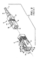
- a commercially available fibre optic plug assembly is shown generally at 2 which is insertable and latchably connected to a receptacle jack assembly shown at 4.
- This known fibre optic connector 2 is comprised of an inner plug body shown generally as 6 and an outer plug housing 8.
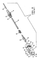
- the inner plug body 6 shown in Figure 2 is shown in Figure 3 exploded to include an insulative housing body 10, a ferrule 12, a coil spring 14, insulative tubing 16, and an inner body portion 18.
- the insulative housing body 10 includes an inner cavity 20 for receiving the ferrule 12 and a rear portion of the inner cavity 20 is profiled to receive a front end 22 of the inner body portion 18 such that the ceramic ferrule 12 is floatable within the insulative housing body 10 and spring loaded between a piston portion 24 of the ferrule assembly and an outer flange 26 of the inner body portion 18.
- an optical fibre 28 is slidably receivable through the inner body portion 18, insulative tubing 16, the coil spring 14, and into its final position within the ferrule 12, whereby the ferrule 12 and inner body portion 18 are received into the insulative housing body 10 for spring loaded retention therein.
- the housing body to includes upper and lower surfaces 30 and side surfaces 32.
- the insulative housing body 10 has chamfered surfaces as 34 providing a polarizing feature for the insulative housing body 10 as will be described in greater detail herein.
- the insulative housing body 10 has recessed surfaces at 36 which extend rearwardly to a transverse rib 38, behind which is a further recessed surface at 40. Continuing rearwardly, a ramped surface is provided at 42 which leads up to a raised stop surface 44.
- the lower side of the insulative housing body 10 as viewed in Figure 3 is identical to the top surface. However, as viewed in Figure 3, only one such surface is visible.
- the outer plug housing 8 is shown in greater detail and includes an inner cavity at 50 for slidably receiving the housing body 10, from the rear thereof, into a locked condition.
- the cavity 50 is provided with surfaces 52 which correspond to the chamfered surfaces 34 for correct polarization of the housing body 10 into the outer plug housing 8.
- the outer plug housing 8 is provided with opposite latching openings at 54 which extend toward the front mating face 56.
- the openings 54 define two side walls 58 flanking the opening 54 and which are interconnected by upper and lower bridge portions 60.
- the side walls 58 extend rearwardly from the front face 56 and include camming surfaces 62 which extend obliquely rearwardly to a top surface 64 of the outer housing 8.
- a recess is formed including a declining edge 66 and a horizontal edge 68.
- a notch is formed at 70 which forms a stop member for the housing 8, as will be described in greater detail herein.
- the housing 8 includes a polarizing lug 72 on one side only of the housing for correct polarization with the receptacle assembly 4.
- the inner plug body 6 can now be slidably received into the rear of the outer plug housing 8 to a fully locked position, as shown in Figure 1, where the raised stop surface 44 is received within the notch 70, which prevents withdrawal of the plug body 6.
- the plug body 6 is also moveable forwardly within the plug housing 8, to a position where the transverse rib 38 abuts a rear edge of the bridge portion 60.
- the jack assembly 4 is comprised of two identical jack receptacle halves 80 having flanges 82 which can be butted one to the other and fixed in place by such means as adhesive or ultrasonic welding.
- the jack assembly 4 further includes two identical latch members 84 which receive between them a fibre aligning ferrule 85.
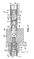
- the ferrule 85 is received within openings 86 in the rear of the latch members 84, and is retained within cylindrical sleeve portions 88 of the latch members 84 by way of a shoulder 90 at the front end of the cylindrical sleeves 88, as best shown in Figure 4 and 5.
- the latch members 84 further include latch extensions 91 which include individual latch projections 92, which are flanked by side wing portions at 94.
- a metal spring clip member 95 can be clipped to one of the receptacle halves 80, whereby the jack assembly 4 can be clipped to a panel, such as a mother board 100 as shown in Figure 5, where the jack assembly 4 is held to the mother board 100 between the flanges 82 and a locking lance found on the clip member 95.
- the identical jack receptacle halves 80 each includes a polarizing slot 98 for receiving the polarizing lug 72 on the plug assembly 2.
- the plug assembly 2 can be received within a receiving cavity 99 ( Figure 5) of the jack assembly 4 such that the ferrule 12 is positioned within the aligning ferrule 85 in the jack assembly 4.
- the wing members 94 ( Figure 4) on the latch extensions 91 are as wide as, the cam surfaces 62, ( Figure 2) but narrower than inner surfaces 71 ( Figure 1) on the side walls 58 ( Figure 2).
- the outer plug housing 8 can be moved rearwardly to the position where the front edge of the transverse rib 38 abuts the rear edge of the bridge portion 60 ( Figure 2) causing the outer wings portions 94 ( Figure 4) to ride up the surfaces 66 and be situated on the upper surface 64 ( Figure 2). This causes raising up of the latch member 92, such that further rearward movement of the outer plug housing 8 causes removal of the entire plug assembly 2.
- the invention proposes that a fibre optic plug connector assembly similar to that disclosed in Figures 1 through 3 is mounted on a daughter board along side of a receptacle connector similar to that disclosed in EP-A- 0422785. Similarly, a receptacle assembly similar to that disclosed in Figures 4 through 5 above would be interconnected to the mother board along side the tab header which is also described in the above mentioned European Patent Application. While the combination of fibre connectors and a connector system as disclosed in the above mentioned European Patent Application is highly desirable, new complications are added by their combination.
- FIG. 6 a fibre optic system useable in combination with electrical connectors, so-called hybrid connectors, is shown.
- the plug which mounts from the left hand side of the mother board can be, and in fact is shown to be, identical to the prior art plug connector of Figure 1,
- the receptacle assembly is somewhat different from that shown in Figure 1 and is therefore labeled by reference numeral 204.
- the jack receptacle half 80 and inner latch member 84 are basically the same as that described above with reference to Figures 1-5.
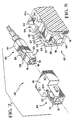
- a plug assembly having some similar features to the plug assembly 2 is generally shown at 102 with an outer housing 104 mounted to a printed circuit daughter board 101 (Fig. 6) and an inner plug body 106 that is slidably received within a cavity 111 of the outer housing 104.
- the plug body 106 has an insert housing 109 ( Figure 7) comprising an inner cavity 110 in which is mounted (Fig. 6) a coil spring 112 that pushes on a piston 114, and to the piston 114 is mounted a ferrule 116 which has a thin central bore for receiving an optical fibre.
- the insert housing 109 is shown having a shroud 118 surrounding the ferrule 116.
- the plug body 106 also has a transverse rib of a plug latching means 128 having a recess 126 therebehind.
- the plug body 106 has a resilient thrust lance 150 which, for example, could be clipped around the insert housing 109, or can be an integral part of the plug body 106.
- the outer housing 104 includes camming members 120 with a tapered front camming surface 124, an upper surface 125, a tapered rear release surface 122 and a lower surface 121. There are two camming members 120 separated by an opening 127. At a front end of the outer housing 104 is a bridge portion 131 that joins the camming members 120. The bridge 131 also serves to retain forward extraction of the plug body 106, whereby forward extraction of the plug body 106 causes the transverse rib 128 of the plug body 106 to abut the bridge 131.
- the insert housing 109 has an outer peripheral surface 151 that is substantially profiled as an inner surface 153 of the cavity 111 such that the plug body 106 is slidably held within the cavity 111.
- the resilient thrust lances 150 that project obliquely rearwardly are engageable with a shoulder 152 of the outer housing 104.
- the plug body 106 is held in an opposite sense by the transverse rib of the plug latching means 128 against the bridge portion 131.
- the thrust lances 150 enable insertion of the plug body 106 into the plug assembly 2 because resilient thrust lances 150 are engaged with the shoulder 152 of the outer housing 104 whilst spring forces on the butting ferrules 12, 116 provoke a rearwards pushing force on the plug body 106. It should be pointed out at this point that the ferrule 116 extends outwardly beyond the shroud 118 further than the corresponding ferrule 12 beyond its corresponding shroud 35, for reasons which will be apparent herein.
- a jack assembly 204 is shown, which is similar in nature to the jack assembly 4 as described above.
- the mother board side can have a jack receptacle half 80 similar to that described above, as well as a inner latch member 84 which is identical to that described above.
- a special jack housing part 280 is required having centrally positioned thrust disengagement means 248 in the form of ribs positioned adjacent to the mating face of the jack housing 280, such that the width of the thrust engagement means 248 are profiled to be received between the two camming members 120 ( Figure 8).
- a different latch member 284 is also required, which has jack latching arms 291 substantially longer than the corresponding latch arms 91 of the opposite side, for reasons which will be described in greater detail herein.
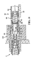
- FIG. 9 The latching sequence is best shown in Figures 9 to 13, whereby, in Figure 9, the plug assembly 102 is shown partially inserted into a cavity 213 of the jack assembly 204 with the ferrule 116 partially inserted into the aligning ferrule 85 and the jack latching arms 291 biased resiliently outwards due to engagement of the wings 294 with the camming surface 124, 125.
- the latching protrusion 292 passes over the bridge portion 131 between the camming members 120.
- Figure 10 shows the latching protrusion 292 within a recess 126 of the inner plug body 106 and behind the transverse rib 128 preventing rearward extraction thereof.
- the latching protrusions 292 project through the opening 127 between camming members 120 (also see Figure 8) and the wings 294 rest on the lower camming surfaces 121.
- the shroud 118 is over the center part 288 and the ferrules 12, 116 abut each other with a spring force.
- optical connection between the two plug assemblies 2, 102 is achieved and the plugs are releasably latched to the jack assembly 204. It is important to note that the shroud 118, unlike its counterpart 35, is spaced from the end surface 289, when in the position shown in Figure 10.
- the jack assembly 204 is provided with thrust desengagement means in the form of actuator ribs 248 that slide between the camming members 120 of the plug assembly 102, as seen in Figures 9, 10, and 11 and the ribs 248 have an inner surface 249 ( Figure 6) very close to the outer surface 151 of the plug body 106.
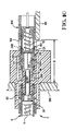
- Figure 11 illustrates the daughter board 101 and plug assembly 102 inserted even further into the jack assembly 204 until the thrust disengagement means 248 in form of ribs are inserted past the shoulder 152 into the rib slots 151a of the outer housing 104, the resilient thrust lances 150 being deflected inwards such that they disengage with the shoulder 152.
- Figure 11 actually represents an instantaneous view, as in this position the plug body 106 is no longer thrust forward by the resilient thrust lances 150 and would therefore spring rearwards until the latching protrusions 292 catch the transverse ribs 128, as shown in Figure 12.
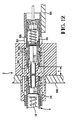
- the force loop of the connection as shown in Figures 12 and 13 is contained within the connector and is as follows: plug ferrule 116-piston 114-spring 112-insert housing 109-jack latching means 291-inner plug body 6-coil spring 14-jack piston 24-ferrule 12.
- the aforementioned force loop does not load the boards, as was mentioned above, when the thrust means 150, 152 were engaged.
- the outer housing 104 and, thus, the daughter board 101 can thereafter be slid forwards with virtually no resistance to the position of Figure 13 and back again to the position of Figure 12, thereby allowing a tolerance T in the axial spacing of the daughter board 101 to the mother board 100, as represented in Figure 12
- FIG. 18 an alternative embodiment of plug connector is shown in 102' whereby the thrust lances 150' are integrally molded with the insert housing 109 and include camming surfaces 149' which cooperate with the thrust disengagement means in form of ribs 248 on the jack housing to disconnect the insert housing 109 from the outer housing 104.
- Figure 18 further shows an alternative latch arm 91' which is reversely formed and includes integral wing members 94'.
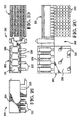
- FIG 19 a further connector assembly is shown in Figure 19 at 300 comprising an electrical connector housing portion 301 and a fibre plug portion 302 having an outer housing 304.
- Any number of a plurality of cavities can be provided at 311 which will receive the inner plug bodies 106 ( Figure 7) in an identical manner.
- Camming members 320 are provided adjacent each cavity 311 for latching interconnection with the plug body 106 as previously described.
- the housing 304 has a lower surface 330 for abutment against the daughter board and a plurality of aligning posts 332 extending therefrom for correct positioning of the housing 304 on the daughter board.
- the connector portion 301 includes a plurality of terminal inserts 340, which are similar to above mentioned European Application number (0 422 785).
- the invention described above relates to the preferred embodiment. one could imagine, however, many different shapes sizes and attachment points of the plug housing, plug latches, jack housing, jack insert, thrust means and the number and shape of the camming members, as well as the number of optical fibres mounted within the connector, without departing from the scope of this invention.
Abstract
Description
- This invention relates to a mechanism for latching an optical fibre connector and, in particular, a latching mechanism for a connector making optical connection between a panel or mother board and a circuit board.
- It is relatively common in the electronics industry, to transfer signals by way of an optical fibre due to a number of advantages that light transmission has over transmission of electrical signals, namely the very high transmission rate of signals and the insensitivity of light signals to electrical and magnetic fields. One common example of high speed data transmission is between substrate boards with printed electrical circuits thereon, whereby it is often desirable to have both electrical and optical connection between the boards, this connection often occurring between a mother board and daughter boards.
- An optical fibre cable is typically built up of an inner core surrounded by cladding and, therearound, fibres for reinforcement and, further, a protective plastic insulation. The core carries all or most of the light and is usually made of glass or plastic, whereby the diameter of this core may even be as small as two to eight microns. The cladding surrounding the core is typically made of plastic or glass and serves to keep the light within the inner core due to the specifically chosen, and different, refraction indexes of the core and cladding, whereby the outer diameter of this cladding may be around twenty to one hundred and twenty five microns. The very small diameter of the inner, light transmitting core means that great accuracy is needed when coupling two optical fibres together. This is achieved by feeding the core and cladding through the bore of a precisely manufactured ferrule and holding it therein by bonding, the optical fibre projecting through the tip of the ferrule, and the tip of the ferrule is then finely polished so that the optical fibre is flush to the tip of the ferrule. The ferrule is then inserted into a precisely manufactured sleeve which accurately centers and aligns the ferrule, whereby the ferrule of another optical cable can be introduced through the other end of the sleeve until both ferrule tips butt against each other in accurate alignment. It is also important to ensure that the gap between the tips of connecting optical fibres is as small as possible and remains constant, thus requiring that the ferrules press against each other. This is achieved by springs mounted in the optical fibre connector and pushing against the ferrule. The spring also absorbs the varying axial positions of the ferrule tips. In order to allow the accurate centering of the ferrules in the sleeve, it is necessary to allow the ferrules to "float" with respect to the connector, this being achieved, for example, by leaving some play between the ferrule and the housing.
- One of the difficulties of making optical connection from board to board arises from the inaccurate spacing of the boards which could be caused, for example, by using a hybrid connector where a number of adjacent optical and/or electrical connectors are positioned on a board and simultaneously plugged into mating connectors on the mother board. Electrical connectors can be easily designed for absorption of two or three millimeters of axial misalignment by simply making the receptacle and mating pin or tab terminal sufficiently long. The problem with optical connectors, however, is that the axial misalignment is absorbed by the spring means as mentioned above, which may produce either a very high compression force or insufficient compression force. This varying spring force is undesirable due to the potentially high loads on the mother board and the uncontrolled butting forces of the ferrules. Additionally, it is desirable to avoid taking up the spring forces through the boards as it causes them to warp and also requires stronger and more expensive structural support thereof.
- Some of the above problems have been partially overcome by the prior art described in "Compact and Self-Retentive Multi-Ferrule Optical Back Panel connector" published in "Journal of Light Wave Technology, VOL. 10, NO. 10, October 1992", pages 1356-1362. This reference describes a jack mounted to a back panel and a plug mounted to a printed circuit board for optical connection therebetween, whereby the plug has a latching mechanism for latching to an inner housing of the jack. The plug also has a latch release which disconnects the plug and jack from an outer housing of the jack, this outer housing being connected to the backpanel. This solution provides a means of releasing the connection spring forces from the boards and also allows axial movement of the plug and jack with respect to the backpanel, thereby absorbing axial tolerances. One of the problems, however, associated to this solution is that the backpanel jack may have a considerable number of optical connections, whereby the optical cables leading into the rear of the back panel jack are relatively heavy and stiff, thereby loading the jack.
- The plug, however, must be able to slide within an outer housing meaning that the fixture between the jack and outer housing must allow a little play. Not only is the fixture of the jack to the backpanel thus weakened by the sliding requirement, but sliding of the jack within the outer housing is made more difficult due to the increased frictional force and tilting of the jack within the outer housing because of the loading from the optical cables.
- An optical fibre connector which can be coupled or decoupled by simple insertion and removal operation without applying ferrule connecting force to other elements is described in EP-A-430 107. The optical connector, which corresponds to that defined in the preamble of claim 1, comprises a first housing, a second housing, a third housing slidably held within the second housing, a first engage mechanism provided between the second and third housing for engaging these two housings when the first and third housings are not coupled, a second engage mechanism provided between the first and third housings, for engaging these two housings when the first housing is coupled to the second and third housings. The connector further comprises a first release member provided for the first housing, for releasing the first engage mechanism when the third housing is engaged to the first housing and a second release member provided for the second housing for releasing the second engage mechanism when the second housing is coupled to the third housing or the first housing is decoupled from the second and third housings. Further, to allow the optical connector to be preferably applicable to a plug-in connector with the smallest possible dimensions and with the highest possible package density, a novel connector floating structure, a novel slidable ferrule supporting structure, a strong optical plug connection mechanism, a reliable optical plug or jack insertion structure, a cleanable and replaceable connector jack etc. are also disclosed.
- One of the objects of this invention is to provide an optical connector that can absorb axial misalignment and yet have a strong and fixed connection between the plug and the jack.
- Another object of this invention is to provide an optical connector that exerts no significant forces through the objects to which they are mounted.
- Yet another object of this invention is to provide an optical connector that can absorb axial misalignment without affecting the spring forces within the connector.
- Yet another object of this invention is to provide a reliable latching mechanism for an optical connector that can be very easily latched and unlatched without the need for any tools.
- A further object of the invention is to provide an optical connector particularly suitable for use in a hybrid connection system comprised of both optical and electrical connectors, where the optical connectors have the ability to absorb axial tolerance necessary for the electrical connector.
- The present invention consists in a fibre optic connector assembly as defined in claim 1.
- A preferred embodiment of this invention will now be described in more detail by way of example, with reference to the accompanying drawings, in which:
- Figure 1 is an isometric view of a commercially available plug and jack assembly;
- Figure 2 is an exploded view of the plug assembly shown in Figure 1;
- Figure 3 shows an exploded view of the plug body assembly of Figure 2;
- Figure 4 shows an exploded view of the receptacle assembly shown in Figure 1,
- Figure 5 shows a cross sectional view through the axial center line of the receptacle assembly of Figures 1 and 4;
- Figure 6 is a cross sectional view of a jack of the present invention about to be inserted into a plug;
- Figure 7 shows an exploded isometric view of a single position plug connector in accordance with the present invention;
- Figure 8 is a detailed isometric view of the front latching profile for the housing shown in Figure 7;
- Figures 9 to 13 show the complete latching sequence of the jack and plug whereby Figure 11 is an instantaneous view of the release of the thrust means;
- Figures 14 to 17 show the unlatching sequence of the plug and jack;
- Figure 18 is a cross sectional view of a slightly different embodiment of an optical connector with the plug and jack housings in solid lines;
- Figure 19 is a front plan view of an integral housing for a hybrid connector carrying both optical and electrical contacts;
- Figure 20 shows a lower plan view of the housing shown in Figure 19; and
- Figure 21 shows a side view of the housing shown in Figure 19.
-
- With reference first to Figure 1, a commercially available fibre optic plug assembly is shown generally at 2 which is insertable and latchably connected to a receptacle jack assembly shown at 4. This known fibre
optic connector 2 is comprised of an inner plug body shown generally as 6 and anouter plug housing 8. - With reference now to Figures 2 and 3 the
plug assembly 2 will be described in greater detail. Theinner plug body 6 shown in Figure 2, is shown in Figure 3 exploded to include aninsulative housing body 10, aferrule 12, acoil spring 14,insulative tubing 16, and aninner body portion 18. Theinsulative housing body 10 includes aninner cavity 20 for receiving theferrule 12 and a rear portion of theinner cavity 20 is profiled to receive afront end 22 of theinner body portion 18 such that theceramic ferrule 12 is floatable within theinsulative housing body 10 and spring loaded between apiston portion 24 of the ferrule assembly and anouter flange 26 of theinner body portion 18. Thus anoptical fibre 28 is slidably receivable through theinner body portion 18,insulative tubing 16, thecoil spring 14, and into its final position within theferrule 12, whereby theferrule 12 andinner body portion 18 are received into theinsulative housing body 10 for spring loaded retention therein. - The housing body to includes upper and
lower surfaces 30 andside surfaces 32. Theinsulative housing body 10 has chamfered surfaces as 34 providing a polarizing feature for theinsulative housing body 10 as will be described in greater detail herein. Theinsulative housing body 10 has recessed surfaces at 36 which extend rearwardly to atransverse rib 38, behind which is a further recessed surface at 40. Continuing rearwardly, a ramped surface is provided at 42 which leads up to a raisedstop surface 44. It should be appreciated that, the lower side of theinsulative housing body 10 as viewed in Figure 3 is identical to the top surface. However, as viewed in Figure 3, only one such surface is visible. - With reference now to Figure 2, the
outer plug housing 8 is shown in greater detail and includes an inner cavity at 50 for slidably receiving thehousing body 10, from the rear thereof, into a locked condition. Thecavity 50 is provided withsurfaces 52 which correspond to thechamfered surfaces 34 for correct polarization of thehousing body 10 into theouter plug housing 8. Theouter plug housing 8 is provided with opposite latching openings at 54 which extend toward thefront mating face 56. Theopenings 54 define twoside walls 58 flanking theopening 54 and which are interconnected by upper andlower bridge portions 60. Theside walls 58 extend rearwardly from thefront face 56 and include camming surfaces 62 which extend obliquely rearwardly to atop surface 64 of theouter housing 8. On the inner surface of theside walls 58, a recess is formed including a decliningedge 66 and ahorizontal edge 68. At the rear edge of theopening 54, a notch is formed at 70 which forms a stop member for thehousing 8, as will be described in greater detail herein. Finally, thehousing 8 includes apolarizing lug 72 on one side only of the housing for correct polarization with the receptacle assembly 4. - The
inner plug body 6 can now be slidably received into the rear of theouter plug housing 8 to a fully locked position, as shown in Figure 1, where the raisedstop surface 44 is received within thenotch 70, which prevents withdrawal of theplug body 6. Theplug body 6 is also moveable forwardly within theplug housing 8, to a position where thetransverse rib 38 abuts a rear edge of thebridge portion 60. - With reference now to Figures 1, 4 and 5, the jack assembly 4 will be described in greater detail. The jack assembly 4 is comprised of two identical jack receptacle halves 80 having
flanges 82 which can be butted one to the other and fixed in place by such means as adhesive or ultrasonic welding. The jack assembly 4 further includes twoidentical latch members 84 which receive between them afibre aligning ferrule 85. Theferrule 85 is received withinopenings 86 in the rear of thelatch members 84, and is retained withincylindrical sleeve portions 88 of thelatch members 84 by way of ashoulder 90 at the front end of thecylindrical sleeves 88, as best shown in Figure 4 and 5. Thelatch members 84 further includelatch extensions 91 which includeindividual latch projections 92, which are flanked by side wing portions at 94. A metalspring clip member 95 can be clipped to one of the receptacle halves 80, whereby the jack assembly 4 can be clipped to a panel, such as amother board 100 as shown in Figure 5, where the jack assembly 4 is held to themother board 100 between theflanges 82 and a locking lance found on theclip member 95. Finally, the identical jack receptacle halves 80 each includes apolarizing slot 98 for receiving thepolarizing lug 72 on theplug assembly 2. - Interconnection and disconnection of the
plug assembly 2 to the jack assembly 4 will now be described in greater detail. Theplug assembly 2 can be received within a receiving cavity 99 (Figure 5) of the jack assembly 4 such that theferrule 12 is positioned within the aligningferrule 85 in the jack assembly 4. It should be appreciated that the wing members 94 (Figure 4) on thelatch extensions 91 are as wide as, the cam surfaces 62, (Figure 2) but narrower than inner surfaces 71 (Figure 1) on the side walls 58 (Figure 2). Therefore, movement of theplug assembly 2 into the jack assembly 4 causes theouter wing members 94 to ride up cam surfaces 62 to a position where the wing members are on thetop surface 64, whereby continued insertion of theplug assembly 2 causes thewing members 94 to ride down thesurface 66, to a resting position on surface 68 (Figure 2). This positions thelatch projection 92 of the jack assembly 4 behind thetransverse rib 38 on thehousing body 10. Due to the spring load on the front face of theferrule 12, theinner plug body 6, when mated, is always situated in such a position so that the latching engagement ofprojection 92 is in an abutting relation with thetransverse rib 38. A pulling force against theinner body portion 18 or on the fibre cable 7 will not remove theplug assembly 2 from the jack assembly 4 due to the latching engagement ofprojection 92 behind thetransverse rib 38. - To extract the
plug assembly 2 from the jack assembly 4, theouter plug housing 8 can be moved rearwardly to the position where the front edge of thetransverse rib 38 abuts the rear edge of the bridge portion 60 (Figure 2) causing the outer wings portions 94 (Figure 4) to ride up thesurfaces 66 and be situated on the upper surface 64 (Figure 2). This causes raising up of thelatch member 92, such that further rearward movement of theouter plug housing 8 causes removal of theentire plug assembly 2. - A substantial improvement has been made to the above mentioned conventional connector system for use, for example, on daughter board connectors and, preferably, in combination with electrical connectors having pins and mating receptacles. With more particularity, the invention proposes that a fibre optic plug connector assembly similar to that disclosed in Figures 1 through 3 is mounted on a daughter board along side of a receptacle connector similar to that disclosed in EP-A- 0422785. Similarly, a receptacle assembly similar to that disclosed in Figures 4 through 5 above would be interconnected to the mother board along side the tab header which is also described in the above mentioned European Patent Application. While the combination of fibre connectors and a connector system as disclosed in the above mentioned European Patent Application is highly desirable, new complications are added by their combination.
- A requirement for such a system as described in the above mentioned European Patent Application is that there must be axial tolerance between mating connectors of 2.5 mm, for example. Therefore, a fibre optic system, as described above with reference to Figures 1-5, is not useable as this fibre optic system would substantially load the mother board and daughter board. For example, if a connector plug assembly similar to that of Figure 2 were mounted directly on a daughter board, and the electrical plug and fibre plug were received within their respective mating tab header and fibre receptacle and, brought into mating engagement, to the position where the fibre plug is fully latched, that is, where the
latch projection 92 is seated behind thetransverse rib 38, as described above, it may still be necessary, due to the tolerance factors as described, to move the daughter board further forward another 2.5 mm. While forward movement of the daughter board would be possible, due to thecoil spring 14, the additional force added to the ferrule by added deflection in the coil spring would be unbearable for the daughter board and mother board as the full axial load is taken up thereby. - With reference now to Figure 6, a fibre optic system useable in combination with electrical connectors, so-called hybrid connectors, is shown. It should be recognized that the plug which mounts from the left hand side of the mother board can be, and in fact is shown to be, identical to the prior art plug connector of Figure 1, As shown in Figure 6, the receptacle assembly is somewhat different from that shown in Figure 1 and is therefore labeled by
reference numeral 204. However, thejack receptacle half 80 andinner latch member 84 are basically the same as that described above with reference to Figures 1-5. - With reference now to Figures 6 and 7, a plug assembly having some similar features to the
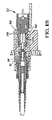
plug assembly 2 is generally shown at 102 with anouter housing 104 mounted to a printed circuit daughter board 101 (Fig. 6) and aninner plug body 106 that is slidably received within acavity 111 of theouter housing 104. Theplug body 106 has an insert housing 109 (Figure 7) comprising aninner cavity 110 in which is mounted (Fig. 6) acoil spring 112 that pushes on apiston 114, and to thepiston 114 is mounted aferrule 116 which has a thin central bore for receiving an optical fibre. - Referring now to Figure 7, the
insert housing 109 is shown having ashroud 118 surrounding theferrule 116. In a similar manner to theprevious plug body 6, theplug body 106 also has a transverse rib of a plug latching means 128 having arecess 126 therebehind. Rather than having a raised surface, such as 44 shown in the embodiment of Figure 1, theplug body 106 has aresilient thrust lance 150 which, for example, could be clipped around theinsert housing 109, or can be an integral part of theplug body 106. - With respect now to Figure 8, the
outer housing 104, includescamming members 120 with a taperedfront camming surface 124, anupper surface 125, a taperedrear release surface 122 and alower surface 121. There are twocamming members 120 separated by anopening 127. At a front end of theouter housing 104 is abridge portion 131 that joins thecamming members 120. Thebridge 131 also serves to retain forward extraction of theplug body 106, whereby forward extraction of theplug body 106 causes thetransverse rib 128 of theplug body 106 to abut thebridge 131. - Referring back to Figure 6, the
insert housing 109 has an outerperipheral surface 151 that is substantially profiled as aninner surface 153 of thecavity 111 such that theplug body 106 is slidably held within thecavity 111. The resilient thrust lances 150 that project obliquely rearwardly are engageable with ashoulder 152 of theouter housing 104. Theplug body 106 is held in an opposite sense by the transverse rib of the plug latching means 128 against thebridge portion 131. The thrust lances 150 enable insertion of theplug body 106 into theplug assembly 2 because resilient thrust lances 150 are engaged with theshoulder 152 of theouter housing 104 whilst spring forces on the buttingferrules plug body 106. It should be pointed out at this point that theferrule 116 extends outwardly beyond theshroud 118 further than the correspondingferrule 12 beyond its correspondingshroud 35, for reasons which will be apparent herein. - As shown in Figure 6, a
jack assembly 204 is shown, which is similar in nature to the jack assembly 4 as described above. As mentioned above, the mother board side can have ajack receptacle half 80 similar to that described above, as well as ainner latch member 84 which is identical to that described above. However, on the daughter board side, a specialjack housing part 280 is required having centrally positioned thrust disengagement means 248 in the form of ribs positioned adjacent to the mating face of thejack housing 280, such that the width of the thrust engagement means 248 are profiled to be received between the two camming members 120 (Figure 8). Adifferent latch member 284 is also required, which hasjack latching arms 291 substantially longer than thecorresponding latch arms 91 of the opposite side, for reasons which will be described in greater detail herein. - The latching sequence is best shown in Figures 9 to 13, whereby, in Figure 9, the
plug assembly 102 is shown partially inserted into acavity 213 of thejack assembly 204 with theferrule 116 partially inserted into the aligningferrule 85 and thejack latching arms 291 biased resiliently outwards due to engagement of thewings 294 with thecamming surface protrusion 292 passes over thebridge portion 131 between thecamming members 120. Figure 10 shows the latchingprotrusion 292 within arecess 126 of theinner plug body 106 and behind thetransverse rib 128 preventing rearward extraction thereof. The latchingprotrusions 292 project through theopening 127 between camming members 120 (also see Figure 8) and thewings 294 rest on the lower camming surfaces 121. In the position shown in Figure 10, theshroud 118 is over thecenter part 288 and theferrules plug assemblies jack assembly 204. It is important to note that theshroud 118, unlike itscounterpart 35, is spaced from theend surface 289, when in the position shown in Figure 10. - This is, however, an unfavorable situation because very little tolerance is allowed in the axial spacing D between the edge of the
daughter board 101 and themother board 100. If the distance between thedaughter board 101 and themother board 100 is required to be less than D, a forward force would have to be applied to theouter housing 104 that would push the thrust lances 150 and thus theinner plug body 106 forwards and, hence, compress thespring 112, whereby thetransverse rib 128 would move forwards, separating away from the latchingprotrusion 292. - If the thrust means 150, 152 are engaged and the distance separating the
daughter 101 andmother board 100 is less than D the force loop would be as follows: - plug ferrule 116-piston 114-spring 112-insert housing
109-thrust lances 150-outer housing 104-daughter board
101-ground or structure-mother board 100- jack assembly
204-latches 92-inner plug body 6-coil spring 14-piston 24-
ferrule 12. As one can see in the above, the spring forces are taken up by theboards boards -
- To avoid the above mentioned undesirable situation, the
jack assembly 204 is provided with thrust desengagement means in the form ofactuator ribs 248 that slide between thecamming members 120 of theplug assembly 102, as seen in Figures 9, 10, and 11 and theribs 248 have an inner surface 249 (Figure 6) very close to theouter surface 151 of theplug body 106. Figure 11 illustrates thedaughter board 101 and plugassembly 102 inserted even further into thejack assembly 204 until the thrust disengagement means 248 in form of ribs are inserted past theshoulder 152 into therib slots 151a of theouter housing 104, the resilient thrust lances 150 being deflected inwards such that they disengage with theshoulder 152. Figure 11 actually represents an instantaneous view, as in this position theplug body 106 is no longer thrust forward by the resilient thrust lances 150 and would therefore spring rearwards until the latchingprotrusions 292 catch thetransverse ribs 128, as shown in Figure 12. - The force loop of the connection as shown in Figures 12 and 13 is contained within the connector and is as follows: plug ferrule 116-piston 114-spring 112-insert housing 109-jack latching means 291-inner plug body 6-coil spring 14-jack piston 24-
ferrule 12. - The aforementioned force loop does not load the boards, as was mentioned above, when the thrust means 150, 152 were engaged. The
outer housing 104 and, thus, thedaughter board 101 can thereafter be slid forwards with virtually no resistance to the position of Figure 13 and back again to the position of Figure 12, thereby allowing a tolerance T in the axial spacing of thedaughter board 101 to themother board 100, as represented in Figure 12 This is allowable, as theouter housing 104, as shown in Figure 12 and 13, is totally released from theplug body 106, the plug body being held to themother board 100, exclusively by the latchingprotrusions 292 on thetransverse ribs 128. - in order to release the plug from the jack, it suffices to pull back the
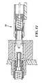
outer housing 104, as shown in Figure 14, that is, by retraction of thedaughter board 101, whereby thewings 294 engage therelease camming surface 122, forcing the jack latching means 291 to bias resiliently outwards, as shown in Figure 15, until thewings 294 pass over the upper camming surface 125 (Figure 16), thus enabling the latchingprotrusions 292 to pass over the transverse ribs of the plug latching means 128. Theplug assembly 102 can then be completely retracted from the jack, as seen in Figure 17, whereby the thrust lances 150 are once again engageable with theshoulder 152 for reconnection of the plug and jack by recommencing the steps illustrated by the Figures 9 to 12. - With reference now to Figure 18, an alternative embodiment of plug connector is shown in 102' whereby the thrust lances 150' are integrally molded with the
insert housing 109 and include camming surfaces 149' which cooperate with the thrust disengagement means in form ofribs 248 on the jack housing to disconnect theinsert housing 109 from theouter housing 104. Figure 18 further shows an alternative latch arm 91' which is reversely formed and includes integral wing members 94'. - While the invention has been described with reference to a single outer plug housing, as shown in Figure 7 at 104, a further connector assembly is shown in Figure 19 at 300 comprising an electrical
connector housing portion 301 and afibre plug portion 302 having anouter housing 304. Any number of a plurality of cavities can be provided at 311 which will receive the inner plug bodies 106 (Figure 7) in an identical manner. Cammingmembers 320 are provided adjacent eachcavity 311 for latching interconnection with theplug body 106 as previously described. As shown in Figure 19, thehousing 304 has alower surface 330 for abutment against the daughter board and a plurality of aligningposts 332 extending therefrom for correct positioning of thehousing 304 on the daughter board. As also shown in Figure 19, theconnector portion 301 includes a plurality ofterminal inserts 340, which are similar to above mentioned European Application number (0 422 785). - The invention described above relates to the preferred embodiment. one could imagine, however, many different shapes sizes and attachment points of the plug housing, plug latches, jack housing, jack insert, thrust means and the number and shape of the camming members, as well as the number of optical fibres mounted within the connector, without departing from the scope of this invention.
Claims (10)
- A fibre optic connector assembly comprising a jack assembly for receiving, at one side thereof, at least one jack ferrule (12), and a plug assembly (102,132) insertable into the jack assembly from the opposite side thereof and having at least one plug ferrule (116) positionable coaxially with said jack ferrule for optically interconnecting optical fibres supported by the ferrules (12,116); said plug assembly comprising an outer housing (104), an inner plug body (106) slidably mounting the plug ferrule(s) and slideable axially within a through cavity (111) of the outer housing, and spring means (112) for resiliently urging the plug ferrule(s) towards the cooperating jack ferrule(s), said inner plug body (106) having radially deflectable outer thrust means (150) for abutting a forward facing shoulder (152) of the outer housing (104) so as to enable insertion of the plug assembly into the jack assembly by movement of the outer housing forwardly into the jack assembly, said outer housing (104) having an opening (127) at the forward end thereof and said inner plug body (106) having outer plug latching means (128) facing said opening (127) for cooperation with the jack assembly (204); and said jack assembly (204) comprising jack latching means (284) cooperating, via the opening (127), with the plug latching means, in response to the plug assembly reaching a predetermined axial position within the jack assembly, for retaining the inner plug body in the jack assembly for optical interconnection of the optical fibres, and thrust disengagement means (248) for radially inwardly deflecting said thrust means to a position clear from said shoulder (152) when said plug assembly is moved further forwardly beyond said predetermined axial position, whereby the outer housing (104) alone is further axially movable over a tolerance absorption distance (T) with respect to the optically and mechanically connected jack assembly (204) and inner plug body (106), said further axial movement not influencing the force exerted by the spring means (112), characterized in that the opening (127) has said forward facing shoulder (152) at a rear end thereof and a bridge portion (131) protruding into the cavity (111) of the outer housing (104) at a forward end of the opening for cooperating with the plug latching means (128) so as to retain the plug body (106) from forward extraction from said cavity (111), and in that the thrust means comprises a rearwardly extending resilient thrust lance (150) which projects obliquely outwards into the opening (127) of the plug housing, and the jack latching means (284) and the thrust disengagement means (248) are so located that, after having passed over the bridge portion (130) upon insertion of the plug assembly into the jack assembly, they are engageable, respectively, with the plug latching means and the thrust lance (150) through the opening (127).
- The connector assembly of claim 1 characterized in that the plug assembly (102,132) comprises a plurality of ferrules (116), each for supporting a fibre, and each ferrule (216) is mounted in a separate plug body (106).
- The connector assembly of claim 1 or 2 characterized in that the or each plug body (106) has an outer surface (151) close to an inner surface (153) of the outer housing (209) such that, when the thrust means (150,352) is disengaged, the plug body (106) is slidable guided axially in the cavity (111).
- The connector assembly of any one of claims 1-3 characterized in that the thrust lance (150) is integral with an insert housing (109) of the plug body (106).
- The connector assembly of any one of claims 1-4 characterized in that the thrust disengagement means (248) is positioned adjacent to the front face of the jack assembly (204).
- The connector assembly of any one of claims 1-5 characterized in that the jack latching means (284) comprises at least one resilient latching arm (291) attached to the jack assembly (204) and extending forwardly therefrom to a free end having a latching protrusion (292) which cooperates with the plug latching means in the form of a rib (128) on the plug body (106) for retention thereof.
- The connector assembly of claim 6 characterized by at least one pair of latching arms (291) per plug ferrule (116).
- The connector assembly of any one of claims 1-7 characterized in that the plug housing (104) has camming members (120) for cooperation with wings (294) attached to the jack latching means (284) of the jack assembly (204), the camming members (120) having camming surfaces (122,125) whereby the wings (294) overlap these surfaces (122,125) such that, during retraction of the plug (102) from the jack assembly (204), the wings (294) engage the camming surfaces (122,125) causing the jack latching means (284) to be resiliently urged outwardly, hence, unlatching the jack assembly (204) from the plug body (106).
- The connector assembly of claim 8 characterized in that the plug (102) has at least one pair of camming members (120) extending from the top or bottom of the plug housing (104) and separated by the opening (127), said opening enabling the jack latching means (284) to engage with the plug latching means, which is in the form of a rib (128) of the plug body (106), for retention of the plug (102) to the jack assembly (204).
- The connector assembly of claim 9 characterized by pairs of the camming members (120) on the top side and opposing bottom side of the plug housing (104), respectively.
Applications Claiming Priority (3)
| Application Number | Priority Date | Filing Date | Title |
|---|---|---|---|
| GB939307488A GB9307488D0 (en) | 1993-04-08 | 1993-04-08 | Optical fibre connector latching mechanism |
| GB9307488 | 1993-04-08 | ||
| PCT/US1994/003511 WO1994024594A1 (en) | 1993-04-08 | 1994-03-30 | Optical fibre connector latching mechanism |
Publications (2)
| Publication Number | Publication Date |
|---|---|
| EP0650602A1 EP0650602A1 (en) | 1995-05-03 |
| EP0650602B1 true EP0650602B1 (en) | 2003-05-07 |
Family
ID=10733648
Family Applications (1)
| Application Number | Title | Priority Date | Filing Date |
|---|---|---|---|
| EP94912364A Expired - Lifetime EP0650602B1 (en) | 1993-04-08 | 1994-03-30 | Optical fibre connector assembly |
Country Status (14)
| Country | Link |
|---|---|
| US (2) | US5542015A (en) |
| EP (1) | EP0650602B1 (en) |
| JP (1) | JPH08502133A (en) |
| KR (1) | KR100321627B1 (en) |
| CN (1) | CN1044289C (en) |
| BR (1) | BR9404890A (en) |
| CA (1) | CA2133215C (en) |
| DE (1) | DE69432625T2 (en) |
| FI (1) | FI115002B (en) |
| GB (1) | GB9307488D0 (en) |
| HU (1) | HUT68028A (en) |
| PL (1) | PL173558B1 (en) |
| RU (1) | RU2128852C1 (en) |
| WO (1) | WO1994024594A1 (en) |
Cited By (1)
| Publication number | Priority date | Publication date | Assignee | Title |
|---|---|---|---|---|
| EP2293129A1 (en) | 2009-09-03 | 2011-03-09 | Tyco Electronics Raychem BVBA | Positioning means for a fibre optic connector assembly, fiber optic connector assembly and fiber termination unit |
Families Citing this family (211)
| Publication number | Priority date | Publication date | Assignee | Title |
|---|---|---|---|---|
| DE4437976C2 (en) * | 1994-10-25 | 1997-07-24 | Henning Faseroptik Gmbh | Coupling device for optical fibers |
| JP3212063B2 (en) * | 1995-03-08 | 2001-09-25 | 日本電信電話株式会社 | Optical receptacle |
| EP0784218A4 (en) * | 1995-07-12 | 1999-09-08 | Sumitomo Electric Industries | Optical fiber connector plug and optical fiber connector |
| TW358552U (en) * | 1995-08-02 | 1999-05-11 | Molex Inc | Adapter for interconnecting optical fiber connectors |
| US5737464A (en) * | 1995-08-31 | 1998-04-07 | Siecor Corporation | Monolithic optical fiber coupler including sleeve with flexible flap |
| DE19539549C1 (en) * | 1995-10-12 | 1996-12-05 | Siemens Ag | Optical connector arrangement for electronic devices |
| JP2000501222A (en) * | 1995-11-06 | 2000-02-02 | ザ ウィタカー コーポレーション | Connection structure for electrical connectors |
| US6045270A (en) | 1995-12-22 | 2000-04-04 | Methode Electronics, Inc. | Massive parallel optical interconnect system |
| US5835594A (en) * | 1996-02-09 | 1998-11-10 | Intel Corporation | Methods and apparatus for preventing unauthorized write access to a protected non-volatile storage |
| US5796896A (en) * | 1996-03-14 | 1998-08-18 | Minnesota Mining And Manufacturing Company | Multi-ferrule fiber optic connector for high density backplane applications |
| EP0805366A1 (en) * | 1996-05-02 | 1997-11-05 | Harting KGaA | Connector |
| US5680494A (en) * | 1996-05-16 | 1997-10-21 | Bell Atlantic Network Services, Inc. | FC-type optical fiber connector adapter |
| US5708742A (en) * | 1996-06-18 | 1998-01-13 | Northern Telecom Limited | Combinations of printed circuit boards and face plates |
| AU4582197A (en) * | 1996-06-21 | 1998-01-07 | Pennoptics, Inc. | Optical fiber connector and method of connecting optical fibers |
| DE19626036A1 (en) * | 1996-06-28 | 1998-01-02 | Whitaker Corp | Optical connector |
| JP3066739B2 (en) * | 1996-07-15 | 2000-07-17 | セイコーインスツルメンツ株式会社 | General-purpose optical connector and basic plug |
| US5815617A (en) * | 1996-10-25 | 1998-09-29 | Federal Signal Corporation | Fiber optic cable connector |
| US5937121A (en) * | 1997-01-03 | 1999-08-10 | The Siemon Company | Adapters for coupling optical fiber |
| DE19807596C2 (en) * | 1997-02-22 | 1999-11-11 | Spinner Gmbh Elektrotech | FO connector |
| SE516303C2 (en) * | 1997-03-20 | 2001-12-17 | Ericsson Telefon Ab L M | Connectors for at least one optical fiber |
| US5867621A (en) * | 1997-04-23 | 1999-02-02 | Siecor Corporation | Adapter and guide pin assembly for coupling of fiber optic connectors |
| DE59801132D1 (en) * | 1997-06-24 | 2001-09-06 | Tyco Electronics Logistics Ag | FERRULENCONTAINER AND CONNECTING ARRANGEMENT FOR AN OPTICAL MULTIPLE FIBER |
| EP0916978B1 (en) * | 1997-11-13 | 2009-04-22 | Diamond SA | Connecting device for optical drawer connexion |
| US6644868B2 (en) | 1997-11-13 | 2003-11-11 | Diamond Sa | Plug construction for an optical plug-and-socket connection |
| US5915058A (en) * | 1998-01-05 | 1999-06-22 | Molex Incorporated | Fiber optic connector assembly |
| US6173099B1 (en) * | 1998-06-05 | 2001-01-09 | Stratos Lightwave, Inc. | Snap-in coupling |
| US6010250A (en) | 1998-07-09 | 2000-01-04 | Sung; Allen L. | Plug for fibre optic cable |
| DE19845854C2 (en) * | 1998-10-05 | 2000-11-02 | Framatome Connectors Int | Optical fiber connector for a mechanically detachable connection between - at least one fiber optic connector pair - at least one fiber optic connector and a circuit board |
| US6116789A (en) * | 1998-11-12 | 2000-09-12 | Delphi Technologies, Inc. | Coupling assembly for coupling glass optical fiber leads to plastic optical fiber leads of a hybrid fiber optic lighting distribution system |
| US6347888B1 (en) | 1998-11-23 | 2002-02-19 | Adc Telecommunications, Inc. | Fiber optic adapter, including hybrid connector system |
| US6454464B1 (en) | 1998-12-28 | 2002-09-24 | Computer Crafts, Inc. | Fiber optic connectors and transceiver test devices |
| US6464408B1 (en) | 1998-12-28 | 2002-10-15 | Computer Crafts, Inc. | Fiber optic connectors |
| FR2789183B1 (en) * | 1999-02-03 | 2001-04-13 | Framatome Connectors France | EASY CLEANING OPTICAL CONNECTOR SYSTEM |
| US6760531B1 (en) | 1999-03-01 | 2004-07-06 | Adc Telecommunications, Inc. | Optical fiber distribution frame with outside plant enclosure |
| US6431762B1 (en) * | 1999-04-09 | 2002-08-13 | Seiko Instruments Inc. | Optical connector adapter |
| DE19922250A1 (en) * | 1999-05-14 | 2000-11-16 | Delphi Tech Inc | Connectors |
| US6325547B1 (en) * | 1999-10-06 | 2001-12-04 | Lucent Technologies Inc. | Optical connector having a housing assembly that is comprised of polyphenylsulfone |
| US6461053B1 (en) * | 1999-10-13 | 2002-10-08 | The Whitaker Corporation | Optical connector having multiple modular housings |
| DE19955316A1 (en) * | 1999-11-17 | 2001-05-23 | Delphi Tech Inc | Connectors |
| US6715931B1 (en) | 1999-12-07 | 2004-04-06 | Wenzong Chen | Self-contained fiber optic connector module |
| US6331079B1 (en) | 1999-12-07 | 2001-12-18 | Molex Incorporated | Mounting system for a connector assembly to a substrate |
| US6361218B1 (en) * | 1999-12-07 | 2002-03-26 | Molex Incorporated | Fiber optic connector module |
| US6406192B1 (en) | 1999-12-07 | 2002-06-18 | Molex Incorporated | Connector assembly floating mount |
| US6371657B1 (en) | 1999-12-07 | 2002-04-16 | Molex Incorporated | Alignment system for mating connectors |
| JP2002214481A (en) * | 2001-01-19 | 2002-07-31 | Hirose Electric Co Ltd | Optical connector |
| DE10004603A1 (en) * | 2000-02-03 | 2001-08-09 | Delphi Tech Inc | Plug connector has adapter spring biased to pre-assembly position that moves to operating position with optical ferrules latched to it when connector parts join together |
| CN1398232A (en) * | 2000-02-07 | 2003-02-19 | 特赫鲁赫鲁器材有限公司 | Portable-pente ski tow |
| US6364536B1 (en) * | 2000-03-30 | 2002-04-02 | Wenzong Chen | Floating connector assembly |
| US6530700B2 (en) * | 2000-04-21 | 2003-03-11 | Teraconnect, Inc. | Fiber optic connector |
| US6580865B1 (en) * | 2000-06-05 | 2003-06-17 | Infineon Technologies North America Corp. | Optical fiber systems |
| ATE246365T1 (en) * | 2000-06-15 | 2003-08-15 | Diamond Sa | CONNECTOR ARRANGEMENT FOR AN OPTICAL PULL-IN CONNECTION |
| US6695485B1 (en) * | 2000-07-28 | 2004-02-24 | Tellabs Operations, Inc. | Bezel for fiber optic components |
| US6682230B1 (en) * | 2000-08-09 | 2004-01-27 | Berg Technology, Inc. | Optical connector and printed circuit board assembly with movable connection |
| JP3769178B2 (en) * | 2000-09-06 | 2006-04-19 | ヒロセ電機株式会社 | Optical adapter |
| US6572273B1 (en) | 2000-11-07 | 2003-06-03 | Itt Manufacturing Enterprises, Inc. | Fiber optic connector with removable alignment sleeve |
| US6572276B1 (en) * | 2000-11-21 | 2003-06-03 | Euromicron Werkezeuge Gmbh | Plug for fiber optic cables with a plug housing |
| AU2002231027A1 (en) | 2000-12-13 | 2002-06-24 | Teraconnect, Inc. | A packaging system for two-dimensional optoelectronic arrays |
| AU2002239622A1 (en) | 2000-12-13 | 2002-06-24 | Teraconnect, Inc. | An optical waveguide assembly for interfacing a two-dimensional optoelectronic array to fiber bundles |
| GB2371374A (en) * | 2001-01-18 | 2002-07-24 | Mao-Hsiang Chen | Optical fibre plug connector with opposing holes for elastic inserts |
| JP3513114B2 (en) * | 2001-03-02 | 2004-03-31 | ヒロセ電機株式会社 | Ferrule holding structure |
| US6944387B2 (en) * | 2001-04-30 | 2005-09-13 | Telect, Inc. | Fiber optic connector tray system |
| US6712523B2 (en) * | 2001-06-01 | 2004-03-30 | Adc Telecommunications, Inc. | Bulkhead adapter with optical fiber for signal attenuation |
| JP4053409B2 (en) * | 2001-12-06 | 2008-02-27 | シャープ株式会社 | Connector and electronic device having the same |
| US6722789B1 (en) | 2001-12-12 | 2004-04-20 | Itt Manufacturing Enterprises, Inc. | Releasable terminus retention |
| DE10219935A1 (en) | 2002-05-03 | 2003-11-27 | Krone Gmbh | Device for an optical fiber connection |
| JP2004029162A (en) * | 2002-06-21 | 2004-01-29 | Sharp Corp | Mechanical locking type connector |
| US7396165B2 (en) * | 2002-11-01 | 2008-07-08 | Finisar Corporation | Counterbore base member for ferrule-type optical connector |
| US6878016B2 (en) * | 2002-12-12 | 2005-04-12 | Symbol Technologies, Inc. | High cycle connector contact system |
| US6619994B1 (en) * | 2002-12-19 | 2003-09-16 | Jess-Link Products Co., Ltd. | Jack plug of digital connector |
| US20040120653A1 (en) * | 2002-12-19 | 2004-06-24 | Zen-Chyuan Chen | Optical fiber joint |
| US7142764B2 (en) | 2003-03-20 | 2006-11-28 | Tyco Electronics Corporation | Optical fiber interconnect cabinets, termination modules and fiber connectivity management for the same |
| US7198409B2 (en) | 2003-06-30 | 2007-04-03 | Adc Telecommunications, Inc. | Fiber optic connector holder and method |
| US7233731B2 (en) * | 2003-07-02 | 2007-06-19 | Adc Telecommunications, Inc. | Telecommunications connection cabinet |
| JP4058394B2 (en) * | 2003-07-10 | 2008-03-05 | シャープ株式会社 | Optical connector receptacle, optical connector, and electronic device |
| JP3910950B2 (en) * | 2003-09-01 | 2007-04-25 | ヒロセ電機株式会社 | Optical connector having shielding mechanism |
| US6874945B2 (en) * | 2003-09-08 | 2005-04-05 | Itt Manufacturing Enterprises, Inc. | Optic fiber connection system with terminus-holding body slidable in housing |
| US6984073B2 (en) * | 2003-10-14 | 2006-01-10 | 3M Innovative Properties Company | Optical and opto-electronic interconnect alignment system |
| US7488115B2 (en) * | 2003-10-28 | 2009-02-10 | Euromicron Werkzeuge Gmbh | Fiber-optical plug as well as a single and double coupler for receiving such a plug |
| US7369741B2 (en) | 2003-11-17 | 2008-05-06 | Fiber Optics Network Solutions Corp. | Storage adapter with dust cap posts |
| US6983095B2 (en) * | 2003-11-17 | 2006-01-03 | Fiber Optic Network Solutions Corporation | Systems and methods for managing optical fibers and components within an enclosure in an optical communications network |
| JP2005189332A (en) * | 2003-12-24 | 2005-07-14 | Three M Innovative Properties Co | Optical connector, optical fiber with connector, optical fiber connecting apparatus and method for connecting optical fiber |
| NL1025381C2 (en) * | 2004-02-02 | 2005-08-03 | Framatome Connectors Int | Optical connector system. |
| NL1025379C2 (en) * | 2004-02-02 | 2005-08-03 | Framatome Connectors Int | Optical connector system. |
| US7074066B2 (en) * | 2004-03-29 | 2006-07-11 | Tyco Electronics Corporation | Sealed electrical connector having internal latching mechanism therefore |
| JP3925933B2 (en) * | 2004-04-02 | 2007-06-06 | 日本航空電子工業株式会社 | Optical connector disassembly jig |
| US20060002660A1 (en) * | 2004-04-22 | 2006-01-05 | Martin Wisecarver | Two-piece nose assembly with solid sleeve for optical subassembly |
| US7427165B2 (en) * | 2004-06-16 | 2008-09-23 | Spectros Corporation | Optical and electrical hybrid connector |
| US7218827B2 (en) | 2004-06-18 | 2007-05-15 | Adc Telecommunications, Inc. | Multi-position fiber optic connector holder and method |
| JP4544928B2 (en) * | 2004-07-16 | 2010-09-15 | スリーエム イノベイティブ プロパティズ カンパニー | Optical connector and optical fiber connection system |
| JP4416591B2 (en) * | 2004-07-16 | 2010-02-17 | スリーエム イノベイティブ プロパティズ カンパニー | Optical connector and optical fiber connection system |
| US7809278B2 (en) * | 2004-07-26 | 2010-10-05 | Hewlett-Packard Development Company, L.P. | Apparatus and method of providing separate control and data channels between arrays of light emitters and detectors for optical communication and alignment |
| US7623793B2 (en) * | 2004-08-10 | 2009-11-24 | Hewlett-Packard Development Company, L.P. | System and method of configuring fiber optic communication channels between arrays of emitters and detectors |
| US7269321B2 (en) * | 2004-08-10 | 2007-09-11 | Hewlett-Packard Development Company, L.P. | System and method of configuring fiber optic communication channels between arrays of emitters and detectors |
| US7251388B2 (en) * | 2004-08-10 | 2007-07-31 | Hewlett-Packard Development Company, L.P. | Apparatus for providing optical communication between integrated circuits of different PC boards and an integrated circuit assembly for use therein |
| US7623783B2 (en) * | 2004-08-10 | 2009-11-24 | Hewlett-Packard Development Company, L.P. | System and method of self-configuring optical communication channels between arrays of emitters and detectors |
| US7653108B2 (en) * | 2004-09-09 | 2010-01-26 | Hewlett-Packard Development Company, L.P. | Apparatus and method of establishing optical communication channels between a steerable array of laser emitters and an array of optical detectors |
| US7229218B2 (en) * | 2004-09-20 | 2007-06-12 | Hewlett-Packard Development Company, L.P. | Apparatus and method of providing an optical connection between PC boards for optical communication |
| US7194181B2 (en) | 2005-03-31 | 2007-03-20 | Adc Telecommunications, Inc. | Adapter block including connector storage |
| US20070036489A1 (en) * | 2005-08-15 | 2007-02-15 | Barbara Grzegorzewska | Industrial interconnect system incorporating transceiver module cage |
| US7623749B2 (en) * | 2005-08-30 | 2009-11-24 | Adc Telecommunications, Inc. | Fiber distribution hub with modular termination blocks |
| US7720343B2 (en) | 2006-02-13 | 2010-05-18 | Adc Telecommunications, Inc. | Fiber distribution hub with swing frame and modular termination panels |
| US7816602B2 (en) | 2006-02-13 | 2010-10-19 | Adc Telecommunications, Inc. | Fiber distribution hub with outside accessible grounding terminals |
| US7760984B2 (en) | 2006-05-04 | 2010-07-20 | Adc Telecommunications, Inc. | Fiber distribution hub with swing frame and wrap-around doors |
| US7496268B2 (en) * | 2006-12-13 | 2009-02-24 | Corning Cable Systems Llc | High density fiber optic hardware |
| US7822310B2 (en) * | 2007-02-28 | 2010-10-26 | Corning Cable Systems Llc | Fiber optic splice trays |
| US7549802B2 (en) * | 2007-06-28 | 2009-06-23 | Verizon Services Corp. | Fiber optic connector |
| US8798427B2 (en) | 2007-09-05 | 2014-08-05 | Corning Cable Systems Llc | Fiber optic terminal assembly |
| US8229265B2 (en) * | 2007-11-21 | 2012-07-24 | Adc Telecommunications, Inc. | Fiber distribution hub with multiple configurations |
| US7889961B2 (en) | 2008-03-27 | 2011-02-15 | Corning Cable Systems Llc | Compact, high-density adapter module, housing assembly and frame assembly for optical fiber telecommunications |
| JP4577793B2 (en) * | 2008-06-04 | 2010-11-10 | ヒロセ電機株式会社 | Waterproof connector and waterproof device using the waterproof connector |
| ES2560802T3 (en) | 2008-08-27 | 2016-02-22 | Adc Telecommunications, Inc. | Fiber optic adapter with integrally molded bushing alignment structure |
| US11294135B2 (en) | 2008-08-29 | 2022-04-05 | Corning Optical Communications LLC | High density and bandwidth fiber optic apparatuses and related equipment and methods |
| US8452148B2 (en) | 2008-08-29 | 2013-05-28 | Corning Cable Systems Llc | Independently translatable modules and fiber optic equipment trays in fiber optic equipment |
| CN102209921B (en) | 2008-10-09 | 2015-11-25 | 康宁光缆系统有限公司 | There is the fibre-optic terminus supported from the adapter panel of the input and output optical fiber of optical splitters |
| US8879882B2 (en) | 2008-10-27 | 2014-11-04 | Corning Cable Systems Llc | Variably configurable and modular local convergence point |
| MX2011005380A (en) | 2008-11-21 | 2011-06-06 | Adc Telecommunications Inc | Fiber optic telecommunications module. |
| EP2194357A1 (en) | 2008-12-03 | 2010-06-09 | Leica Geosystems AG | Optical sensor element for a measuring device and coupling element for this containing measuring device unit |
| ATE534049T1 (en) | 2009-02-24 | 2011-12-15 | Ccs Technology Inc | CABLE HOLDING DEVICE OR ARRANGEMENT FOR USE WITH A CABLE |
| JP4743724B2 (en) * | 2009-02-26 | 2011-08-10 | ヒロセ電機株式会社 | Waterproof connector and waterproof device using the waterproof connector |
| EP2237091A1 (en) | 2009-03-31 | 2010-10-06 | Corning Cable Systems LLC | Removably mountable fiber optic terminal |
| US8699838B2 (en) | 2009-05-14 | 2014-04-15 | Ccs Technology, Inc. | Fiber optic furcation module |
| US9075216B2 (en) | 2009-05-21 | 2015-07-07 | Corning Cable Systems Llc | Fiber optic housings configured to accommodate fiber optic modules/cassettes and fiber optic panels, and related components and methods |
| US8280216B2 (en) | 2009-05-21 | 2012-10-02 | Corning Cable Systems Llc | Fiber optic equipment supporting moveable fiber optic equipment tray(s) and module(s), and related equipment and methods |
| US8712206B2 (en) | 2009-06-19 | 2014-04-29 | Corning Cable Systems Llc | High-density fiber optic modules and module housings and related equipment |
| US8433171B2 (en) | 2009-06-19 | 2013-04-30 | Corning Cable Systems Llc | High fiber optic cable packing density apparatus |
| AU2010263057A1 (en) | 2009-06-19 | 2012-02-02 | Corning Cable Systems Llc | High density and bandwidth fiber optic apparatuses and related equipment and methods |
| US8467651B2 (en) | 2009-09-30 | 2013-06-18 | Ccs Technology Inc. | Fiber optic terminals configured to dispose a fiber optic connection panel(s) within an optical fiber perimeter and related methods |
| PL217893B1 (en) | 2009-10-10 | 2014-08-29 | Inst Wysokich Ciśnień Polskiej Akademii Nauk | Method and apparatus for introducing laser light from at least two laser sources into one fibre |
| JP5182893B2 (en) * | 2009-11-17 | 2013-04-17 | Nttエレクトロニクス株式会社 | Optical connector plug |
| US8625950B2 (en) | 2009-12-18 | 2014-01-07 | Corning Cable Systems Llc | Rotary locking apparatus for fiber optic equipment trays and related methods |
| EP2354824A1 (en) * | 2010-01-29 | 2011-08-10 | CCS Technology Inc. | Hybrid connector |
| US8593828B2 (en) | 2010-02-04 | 2013-11-26 | Corning Cable Systems Llc | Communications equipment housings, assemblies, and related alignment features and methods |
| JP5080600B2 (en) | 2010-02-26 | 2012-11-21 | 日本航空電子工業株式会社 | Plug with built-in optical connector |
| EP2542930A1 (en) | 2010-03-02 | 2013-01-09 | Tyco Electronics Services GmbH | Fibre-optic telecommunication module |
| EP2545405A1 (en) | 2010-03-10 | 2013-01-16 | Corning Cable Systems LLC | Fiber optic pigtail assembly allowing single and mass splicing |
| US9547144B2 (en) | 2010-03-16 | 2017-01-17 | Corning Optical Communications LLC | Fiber optic distribution network for multiple dwelling units |
| EP2548067A4 (en) * | 2010-03-19 | 2014-04-02 | Corning Inc | Fiber optic interface device with translatable ferrule |
| US8913866B2 (en) | 2010-03-26 | 2014-12-16 | Corning Cable Systems Llc | Movable adapter panel |
| US8792767B2 (en) | 2010-04-16 | 2014-07-29 | Ccs Technology, Inc. | Distribution device |
| AU2011265751B2 (en) | 2010-04-16 | 2015-09-10 | Corning Optical Communications LLC | Sealing and strain relief device for data cables |
| EP2381284B1 (en) | 2010-04-23 | 2014-12-31 | CCS Technology Inc. | Under floor fiber optic distribution device |
| US8879881B2 (en) | 2010-04-30 | 2014-11-04 | Corning Cable Systems Llc | Rotatable routing guide and assembly |
| US8705926B2 (en) | 2010-04-30 | 2014-04-22 | Corning Optical Communications LLC | Fiber optic housings having a removable top, and related components and methods |
| US9632270B2 (en) | 2010-04-30 | 2017-04-25 | Corning Optical Communications LLC | Fiber optic housings configured for tool-less assembly, and related components and methods |
| US9075217B2 (en) | 2010-04-30 | 2015-07-07 | Corning Cable Systems Llc | Apparatuses and related components and methods for expanding capacity of fiber optic housings |
| US9519118B2 (en) | 2010-04-30 | 2016-12-13 | Corning Optical Communications LLC | Removable fiber management sections for fiber optic housings, and related components and methods |
| US9720195B2 (en) | 2010-04-30 | 2017-08-01 | Corning Optical Communications LLC | Apparatuses and related components and methods for attachment and release of fiber optic housings to and from an equipment rack |
| US8660397B2 (en) | 2010-04-30 | 2014-02-25 | Corning Cable Systems Llc | Multi-layer module |
| US8718436B2 (en) | 2010-08-30 | 2014-05-06 | Corning Cable Systems Llc | Methods, apparatuses for providing secure fiber optic connections |
| JP5439319B2 (en) * | 2010-09-06 | 2014-03-12 | 株式会社フジクラ | Optical connector and optical connector insertion / extraction method |
| US9547145B2 (en) | 2010-10-19 | 2017-01-17 | Corning Optical Communications LLC | Local convergence point for multiple dwelling unit fiber optic distribution network |
| CN102455468B (en) * | 2010-10-19 | 2015-02-25 | 富士康(昆山)电脑接插件有限公司 | Optical fiber connector and optical fiber connector component |
| US9279951B2 (en) | 2010-10-27 | 2016-03-08 | Corning Cable Systems Llc | Fiber optic module for limited space applications having a partially sealed module sub-assembly |
| US8662760B2 (en) | 2010-10-29 | 2014-03-04 | Corning Cable Systems Llc | Fiber optic connector employing optical fiber guide member |
| CA2819235C (en) | 2010-11-30 | 2018-01-16 | Corning Cable Systems Llc | Fiber device holder and strain relief device |
| EP2671107A1 (en) | 2011-02-02 | 2013-12-11 | Corning Cable Systems LLC | Dense shuttered fiber optic connectors and assemblies suitable for establishing optical connections for optical backplanes in equipment racks |
| US9052468B2 (en) | 2011-03-04 | 2015-06-09 | Corning Cable Systems Llc | Fiber optic adapter mount |
| JP2012220797A (en) * | 2011-04-11 | 2012-11-12 | Furukawa Electric Co Ltd:The | Connecting structure of optical connector |
| US20140016900A1 (en) * | 2011-04-11 | 2014-01-16 | Autonetworks Technologies, Ltd. | Optical connector and ferrule |
| US9008485B2 (en) | 2011-05-09 | 2015-04-14 | Corning Cable Systems Llc | Attachment mechanisms employed to attach a rear housing section to a fiber optic housing, and related assemblies and methods |
| US9188747B2 (en) | 2011-05-23 | 2015-11-17 | Senko Advanced Components, Inc. | True one piece housing fiber optic adapter |
| CN103649805B (en) | 2011-06-30 | 2017-03-15 | 康宁光电通信有限责任公司 | Fiber plant assembly of shell using non-U-width size and associated method |
| US9110266B2 (en) | 2011-07-29 | 2015-08-18 | Corning Cable Systems Llc | Fiber optic cables seal and/or strain relief members, and related assemblies and methods |
| US8953924B2 (en) | 2011-09-02 | 2015-02-10 | Corning Cable Systems Llc | Removable strain relief brackets for securing fiber optic cables and/or optical fibers to fiber optic equipment, and related assemblies and methods |
| US9417418B2 (en) | 2011-09-12 | 2016-08-16 | Commscope Technologies Llc | Flexible lensed optical interconnect device for signal distribution |
| EP2764390B1 (en) | 2011-10-07 | 2020-12-02 | CommScope Technologies LLC | Fiber optic cassette, system, and method |
| US9038832B2 (en) | 2011-11-30 | 2015-05-26 | Corning Cable Systems Llc | Adapter panel support assembly |
| US9219546B2 (en) | 2011-12-12 | 2015-12-22 | Corning Optical Communications LLC | Extremely high frequency (EHF) distributed antenna systems, and related components and methods |
| US8842962B2 (en) | 2012-01-27 | 2014-09-23 | Corning Cable Systems Llc | Fiber optic cable strain relief device and method |
| US10110307B2 (en) | 2012-03-02 | 2018-10-23 | Corning Optical Communications LLC | Optical network units (ONUs) for high bandwidth connectivity, and related components and methods |
| US9004778B2 (en) | 2012-06-29 | 2015-04-14 | Corning Cable Systems Llc | Indexable optical fiber connectors and optical fiber connector arrays |
| US9250409B2 (en) | 2012-07-02 | 2016-02-02 | Corning Cable Systems Llc | Fiber-optic-module trays and drawers for fiber-optic equipment |
| US9081152B2 (en) | 2012-08-30 | 2015-07-14 | Adc Telecommunications, Inc. | Adapter pack with removable sleeves |
| JP6077797B2 (en) * | 2012-08-30 | 2017-02-08 | 矢崎総業株式会社 | Optical connector |
| US9049500B2 (en) | 2012-08-31 | 2015-06-02 | Corning Cable Systems Llc | Fiber optic terminals, systems, and methods for network service management |
| US9042702B2 (en) | 2012-09-18 | 2015-05-26 | Corning Cable Systems Llc | Platforms and systems for fiber optic cable attachment |
| US9146362B2 (en) | 2012-09-21 | 2015-09-29 | Adc Telecommunications, Inc. | Insertion and removal tool for a fiber optic ferrule alignment sleeve |
| US9146374B2 (en) | 2012-09-28 | 2015-09-29 | Adc Telecommunications, Inc. | Rapid deployment packaging for optical fiber |
| ES2792122T3 (en) | 2012-09-28 | 2020-11-10 | Commscope Connectivity Uk Ltd | Fiber optic cassette |
| US9223094B2 (en) | 2012-10-05 | 2015-12-29 | Tyco Electronics Nederland Bv | Flexible optical circuit, cassettes, and methods |
| US8909019B2 (en) | 2012-10-11 | 2014-12-09 | Ccs Technology, Inc. | System comprising a plurality of distribution devices and distribution device |
| US9523829B2 (en) * | 2012-10-18 | 2016-12-20 | Corning Optical Communications LLC | Fiber optic cable sub-assemblies with strain-relief to a circuit board and methods of assembling |
| EP2725397B1 (en) | 2012-10-26 | 2015-07-29 | CCS Technology, Inc. | Fiber optic management unit and fiber optic distribution device |
| EP2725396B1 (en) | 2012-10-26 | 2016-09-14 | CCS Technology, Inc. | Strain relief device for cables and fiber optic distribution device |
| US8985862B2 (en) | 2013-02-28 | 2015-03-24 | Corning Cable Systems Llc | High-density multi-fiber adapter housings |
| US9435975B2 (en) | 2013-03-15 | 2016-09-06 | Commscope Technologies Llc | Modular high density telecommunications frame and chassis system |
| US9360649B2 (en) | 2013-05-22 | 2016-06-07 | Senko Advanced Components, Inc. | Cable guide for fiber optic cables |
| MX2016000475A (en) * | 2013-07-16 | 2016-04-07 | 3M Innovative Properties Co | Connector for telecommunication enclosures. |
| US9488793B2 (en) | 2013-09-10 | 2016-11-08 | Corning Optical Communications LLC | Combined optical fiber and power cable |
| WO2015047392A1 (en) * | 2013-09-30 | 2015-04-02 | Hewlett-Packard Development Company, Lp | Optical blind-mate connector and adapter |
| JP6425003B2 (en) * | 2014-01-17 | 2018-11-21 | 矢崎総業株式会社 | Optical connector and mating structure of optical connector |
| CN106133572B (en) | 2014-01-28 | 2018-11-09 | Adc电信公司 | Slidably optical link module with cable slack management |
| DE102014102733B4 (en) * | 2014-02-28 | 2015-12-17 | Phoenix Contact Gmbh & Co. Kg | Pluggable device combination |
| US9494758B2 (en) | 2014-04-03 | 2016-11-15 | Commscope Technologies Llc | Fiber optic distribution system |
| US9274287B2 (en) * | 2014-05-13 | 2016-03-01 | Senko Advanced Components, Inc. | Optical fiber connector and ferrule |
| WO2016068892A1 (en) * | 2014-10-29 | 2016-05-06 | Hewlett Packard Enterprise Development Lp | Optical connector assembly apparatus |
| EP3268785B1 (en) * | 2015-03-09 | 2020-11-18 | Cotsworks, LLC | Overboot assembly for fiber optic cable terminus |
| EP3296785A4 (en) | 2015-05-15 | 2019-05-29 | ADC Telecommunications (Shanghai) Distribution Co., Ltd. | Alignment sleeve assembly and optical fibre adapter |
| JP6627874B2 (en) * | 2015-06-15 | 2020-01-08 | 日本電気株式会社 | Pluggable optical module and optical communication system |
| CN107735709B (en) * | 2015-06-15 | 2020-06-19 | 日本电气株式会社 | Pluggable optical module and optical communication system |
| CN104991312B (en) * | 2015-06-24 | 2017-01-11 | 中航光电科技股份有限公司 | Optical cable connector |
| US9645323B2 (en) * | 2015-08-27 | 2017-05-09 | Senko Advanced Components, Inc. | Micro hybrid LC duplex adapter |
| CN109073838B (en) * | 2016-03-10 | 2021-03-30 | 康宁光电通信有限责任公司 | Ferrule-based fiber optic connector with ferrule retraction balancing |
| US10295771B2 (en) | 2016-05-03 | 2019-05-21 | Corning Optical Communications LLC | Telecommunications terminal with removable modules |
| US10228521B2 (en) * | 2016-12-05 | 2019-03-12 | Senko Advanced Components, Inc. | Narrow width adapters and connectors with modular latching arm |
| JP6690736B2 (en) * | 2016-12-19 | 2020-04-28 | 日本電気株式会社 | Pluggable optical module and optical transmission system |
| CN106646766A (en) * | 2017-03-01 | 2017-05-10 | 桥运精密部件(苏州)有限公司 | Novel combined type stainless steel tail handle insert core |
| WO2019070682A2 (en) | 2017-10-02 | 2019-04-11 | Commscope Technologies Llc | Fiber optic circuit and preparation method |
| CN109511046B (en) * | 2019-01-14 | 2020-12-18 | 安徽松之梦科技有限公司 | Earphone set |
| TWM590824U (en) * | 2019-06-05 | 2020-02-11 | 光紅建聖股份有限公司 | A frame structure with indicator lights |
| US11199669B1 (en) * | 2020-09-24 | 2021-12-14 | Hewlett Packard Enterprise Development Lp | Modular faceplate optical sub-assembly |
Family Cites Families (12)
| Publication number | Priority date | Publication date | Assignee | Title |
|---|---|---|---|---|
| US4406514A (en) * | 1980-03-26 | 1983-09-27 | Harris Corporation | Single fiber connector for pluggable card or module optical interconnections |
| US4852963A (en) * | 1987-06-30 | 1989-08-01 | American Telephone And Telegraph Company, At&T Bell Laboratories | Optical fiber biconic connector |
| US4872736A (en) * | 1988-04-19 | 1989-10-10 | American Telephone And Telegraph Company, At&T Bell Laboratories | Connector assembly having a latching mechanism |
| US4953941A (en) * | 1988-11-21 | 1990-09-04 | Seikoh Giken Co., Ltd. | Optical fiber connecting device |
| US5121454A (en) * | 1989-11-24 | 1992-06-09 | Nippon Telegraph And Telephone Corporation | Optical connector |
| US5129023A (en) * | 1991-05-14 | 1992-07-07 | At&T Bell Laboratories | Optical fiber connector having enhanced provisions for interconnection and for prevention of optical and mechanical disconnection |
| US5134679A (en) * | 1991-05-20 | 1992-07-28 | At&T Bell Laboratories | Connector for coupling an optical fiber on a backplane to a component on a circuit board |
| JP2538394Y2 (en) * | 1991-05-29 | 1997-06-11 | 住友電気工業株式会社 | Optical connector |
| US5187768A (en) * | 1991-12-19 | 1993-02-16 | Porta Systems Corp. | Fiber optic variable signal attenuator |
| US5285510A (en) * | 1992-12-15 | 1994-02-08 | The Whitaker Corporation | Fiber optic connector |
| US5428703A (en) * | 1994-02-18 | 1995-06-27 | Augat Inc. | One-piece SC fiber optic connector |
| US5432879A (en) * | 1994-05-09 | 1995-07-11 | Augat Inc. | Nondisconnectable FC/PC fiber optic connector assembly |
-
1993
- 1993-04-08 GB GB939307488A patent/GB9307488D0/en active Pending
-
1994
- 1994-03-30 CA CA002133215A patent/CA2133215C/en not_active Expired - Lifetime
- 1994-03-30 EP EP94912364A patent/EP0650602B1/en not_active Expired - Lifetime
- 1994-03-30 DE DE69432625T patent/DE69432625T2/en not_active Expired - Lifetime
- 1994-03-30 PL PL94306206A patent/PL173558B1/en unknown
- 1994-03-30 HU HU9402894A patent/HUT68028A/en unknown
- 1994-03-30 WO PCT/US1994/003511 patent/WO1994024594A1/en active IP Right Grant
- 1994-03-30 RU RU94046288A patent/RU2128852C1/en active
- 1994-03-30 KR KR1019940704437A patent/KR100321627B1/en not_active IP Right Cessation
- 1994-03-30 JP JP6523233A patent/JPH08502133A/en active Pending
- 1994-03-30 BR BR9404890A patent/BR9404890A/en not_active IP Right Cessation
- 1994-04-07 CN CN94104597A patent/CN1044289C/en not_active Expired - Lifetime
- 1994-11-25 US US08/345,063 patent/US5542015A/en not_active Expired - Lifetime
- 1994-12-07 FI FI945741A patent/FI115002B/en not_active IP Right Cessation
-
1996
- 1996-06-25 US US08/671,023 patent/US5764834A/en not_active Expired - Lifetime
Cited By (3)
| Publication number | Priority date | Publication date | Assignee | Title |
|---|---|---|---|---|
| EP2293129A1 (en) | 2009-09-03 | 2011-03-09 | Tyco Electronics Raychem BVBA | Positioning means for a fibre optic connector assembly, fiber optic connector assembly and fiber termination unit |
| WO2011026894A1 (en) | 2009-09-03 | 2011-03-10 | Tyco Electronics Raychem Bvba | Positioning means for a fibre optic connector assembly, a fibre optic connector assembly and fibre termination unit |
| US10007070B2 (en) | 2009-09-03 | 2018-06-26 | CommScope Connectivity Belgium BVBA | Positioning means for a fibre optic connector assembly, a fibre optic connector assembly and fibre termination unit |
Also Published As
| Publication number | Publication date |
|---|---|
| CN1098507A (en) | 1995-02-08 |
| PL173558B1 (en) | 1998-03-31 |
| FI945741A (en) | 1994-12-07 |
| HUT68028A (en) | 1995-05-29 |
| WO1994024594A1 (en) | 1994-10-27 |
| RU94046288A (en) | 1996-10-10 |
| CN1044289C (en) | 1999-07-21 |
| EP0650602A1 (en) | 1995-05-03 |
| DE69432625D1 (en) | 2003-06-12 |
| US5542015A (en) | 1996-07-30 |
| GB9307488D0 (en) | 1993-06-02 |
| HU9402894D0 (en) | 1995-02-28 |
| KR950702038A (en) | 1995-05-17 |
| CA2133215A1 (en) | 1994-10-27 |
| FI115002B (en) | 2005-02-15 |
| RU2128852C1 (en) | 1999-04-10 |
| FI945741A0 (en) | 1994-12-07 |
| PL306206A1 (en) | 1995-03-06 |
| KR100321627B1 (en) | 2002-06-27 |
| CA2133215C (en) | 2002-01-29 |
| BR9404890A (en) | 1999-06-15 |
| JPH08502133A (en) | 1996-03-05 |
| US5764834A (en) | 1998-06-09 |
| DE69432625T2 (en) | 2004-03-25 |
Similar Documents
| Publication | Publication Date | Title |
|---|---|---|
| EP0650602B1 (en) | Optical fibre connector assembly | |
| US5404416A (en) | Optical connector plug | |
| US5151961A (en) | Ferrule alignment assembly for blind mating optical fiber connector | |
| JP2771870B2 (en) | Optical connector | |
| EP0997753B1 (en) | Fiber optic connector assembly | |
| EP0119013B1 (en) | Connector with mechanism for coupling and uncoupling plurality of blocks | |
| EP0338727B1 (en) | Connector assembly having a latching mechanism | |
| US6318903B1 (en) | Optical fiber connector for backplane | |
| EP0803750A1 (en) | Optical connector with immovable ferrule | |
| US10305222B2 (en) | Connector assembly | |
| KR20010095062A (en) | Floating connector assembly | |
| US5054879A (en) | Push/pull fiber optic connector | |
| US5960138A (en) | Backplane connector | |
| US11934020B2 (en) | Optoelectronic connections to printed circuit boards | |
| US10598870B2 (en) | Fiber optic connector with dual multi-fiber ferrules, and cable assemblies and systems including the same | |
| JP2002098860A (en) | Alignment system for optical fiber connector | |
| EP3677939B1 (en) | Optical connector and method for connecting optical connector | |
| EP0015657A2 (en) | Optical fibre connector | |
| US11320600B2 (en) | Fiber optic connector for hardware interiors and method of using same | |
| CN220626715U (en) | Optical fiber connector, optical fiber connection plug and optical fiber connection assembly | |
| US20230142093A1 (en) | Fiber optic adapters for use with fiber optic connectors and methods for coupling fiber optic connectors | |
| CN219552704U (en) | Miniaturized connector | |
| CA2354174C (en) | Optical connector | |
| NO317436B1 (en) | Laser fiber optic switching mechanism |
Legal Events
| Date | Code | Title | Description |
|---|---|---|---|
| PUAI | Public reference made under article 153(3) epc to a published international application that has entered the european phase |
Free format text: ORIGINAL CODE: 0009012 |
|
| 17P | Request for examination filed |
Effective date: 19941213 |
|
| AK | Designated contracting states |
Kind code of ref document: A1 Designated state(s): AT BE CH DE DK ES FR GB GR IE IT LI NL PT SE |
|
| 17Q | First examination report despatched |
Effective date: 19970108 |
|
| RIC1 | Information provided on ipc code assigned before grant |
Free format text: 7G 02B 6/38 A |
|
| RTI1 | Title (correction) |
Free format text: OPTICAL FIBRE CONNECTOR ASSEMBLY |
|
| GRAG | Despatch of communication of intention to grant |
Free format text: ORIGINAL CODE: EPIDOS AGRA |
|
| GRAG | Despatch of communication of intention to grant |
Free format text: ORIGINAL CODE: EPIDOS AGRA |
|
| GRAG | Despatch of communication of intention to grant |
Free format text: ORIGINAL CODE: EPIDOS AGRA |
|
| GRAH | Despatch of communication of intention to grant a patent |
Free format text: ORIGINAL CODE: EPIDOS IGRA |
|
| GRAH | Despatch of communication of intention to grant a patent |
Free format text: ORIGINAL CODE: EPIDOS IGRA |
|
| RBV | Designated contracting states (corrected) |
Designated state(s): DE FR GB IT |
|
| GRAA | (expected) grant |
Free format text: ORIGINAL CODE: 0009210 |
|
| AK | Designated contracting states |
Designated state(s): DE FR GB IT |
|
| REG | Reference to a national code |
Ref country code: GB Ref legal event code: FG4D |
|
| REG | Reference to a national code |
Ref country code: IE Ref legal event code: FG4D |
|
| REF | Corresponds to: |
Ref document number: 69432625 Country of ref document: DE Date of ref document: 20030612 Kind code of ref document: P |
|
| ET | Fr: translation filed | ||
| PLBE | No opposition filed within time limit |
Free format text: ORIGINAL CODE: 0009261 |
|
| STAA | Information on the status of an ep patent application or granted ep patent |
Free format text: STATUS: NO OPPOSITION FILED WITHIN TIME LIMIT |
|
| 26N | No opposition filed |
Effective date: 20040210 |
|
| REG | Reference to a national code |
Ref country code: IE Ref legal event code: MM4A |
|
| PGFP | Annual fee paid to national office [announced via postgrant information from national office to epo] |
Ref country code: IT Payment date: 20120327 Year of fee payment: 19 |
|
| PGFP | Annual fee paid to national office [announced via postgrant information from national office to epo] |
Ref country code: DE Payment date: 20130327 Year of fee payment: 20 Ref country code: FR Payment date: 20130405 Year of fee payment: 20 Ref country code: GB Payment date: 20130327 Year of fee payment: 20 |
|
| REG | Reference to a national code |
Ref country code: DE Ref legal event code: R071 Ref document number: 69432625 Country of ref document: DE |
|
| REG | Reference to a national code |
Ref country code: DE Ref legal event code: R071 Ref document number: 69432625 Country of ref document: DE |
|
| REG | Reference to a national code |
Ref country code: GB Ref legal event code: PE20 Expiry date: 20140329 |
|
| PG25 | Lapsed in a contracting state [announced via postgrant information from national office to epo] |
Ref country code: GB Free format text: LAPSE BECAUSE OF EXPIRATION OF PROTECTION Effective date: 20140329 |
|
| PG25 | Lapsed in a contracting state [announced via postgrant information from national office to epo] |
Ref country code: DE Free format text: LAPSE BECAUSE OF EXPIRATION OF PROTECTION Effective date: 20140401 |