EP0650585B1 - Optischer sensor zur bestimmung von druck und temperatur - Google Patents
Optischer sensor zur bestimmung von druck und temperatur Download PDFInfo
- Publication number
- EP0650585B1 EP0650585B1 EP93904986A EP93904986A EP0650585B1 EP 0650585 B1 EP0650585 B1 EP 0650585B1 EP 93904986 A EP93904986 A EP 93904986A EP 93904986 A EP93904986 A EP 93904986A EP 0650585 B1 EP0650585 B1 EP 0650585B1
- Authority
- EP
- European Patent Office
- Prior art keywords
- pressure
- waveguides
- crystal member
- waves
- waveguide
- Prior art date
- Legal status (The legal status is an assumption and is not a legal conclusion. Google has not performed a legal analysis and makes no representation as to the accuracy of the status listed.)
- Expired - Lifetime
Links
- 239000013078 crystal Substances 0.000 claims abstract description 44
- 230000003287 optical effect Effects 0.000 claims abstract description 7
- 229910052782 aluminium Inorganic materials 0.000 claims description 14
- 229910052691 Erbium Inorganic materials 0.000 claims description 11
- 229910052765 Lutetium Inorganic materials 0.000 claims description 10
- 229910052775 Thulium Inorganic materials 0.000 claims description 10
- 229910052769 Ytterbium Inorganic materials 0.000 claims description 10
- 239000012530 fluid Substances 0.000 claims description 6
- 229910019901 yttrium aluminum garnet Inorganic materials 0.000 claims description 4
- 239000000758 substrate Substances 0.000 claims description 3
- 239000000463 material Substances 0.000 claims description 2
- 230000000717 retained effect Effects 0.000 claims 1
- 238000001228 spectrum Methods 0.000 description 11
- 230000005693 optoelectronics Effects 0.000 description 6
- 239000000835 fiber Substances 0.000 description 4
- 238000004891 communication Methods 0.000 description 3
- 230000003750 conditioning effect Effects 0.000 description 3
- 239000002223 garnet Substances 0.000 description 3
- -1 holmium aluminum Chemical compound 0.000 description 3
- JNDMLEXHDPKVFC-UHFFFAOYSA-N aluminum;oxygen(2-);yttrium(3+) Chemical compound [O-2].[O-2].[O-2].[Al+3].[Y+3] JNDMLEXHDPKVFC-UHFFFAOYSA-N 0.000 description 2
- 238000005452 bending Methods 0.000 description 2
- 238000010586 diagram Methods 0.000 description 2
- 239000003365 glass fiber Substances 0.000 description 2
- 230000009466 transformation Effects 0.000 description 2
- RYGMFSIKBFXOCR-UHFFFAOYSA-N Copper Chemical compound [Cu] RYGMFSIKBFXOCR-UHFFFAOYSA-N 0.000 description 1
- 230000003466 anti-cipated effect Effects 0.000 description 1
- 230000006835 compression Effects 0.000 description 1
- 238000007906 compression Methods 0.000 description 1
- 230000008602 contraction Effects 0.000 description 1
- 229910052802 copper Inorganic materials 0.000 description 1
- 239000010949 copper Substances 0.000 description 1
- 230000007423 decrease Effects 0.000 description 1
- 230000001419 dependent effect Effects 0.000 description 1
- 230000000694 effects Effects 0.000 description 1
- 230000005284 excitation Effects 0.000 description 1
- 239000000284 extract Substances 0.000 description 1
- 238000004519 manufacturing process Methods 0.000 description 1
- 230000004048 modification Effects 0.000 description 1
- 238000012986 modification Methods 0.000 description 1
- 230000010287 polarization Effects 0.000 description 1
- 230000001902 propagating effect Effects 0.000 description 1
- 230000003595 spectral effect Effects 0.000 description 1
Images

Classifications
-
- G—PHYSICS
- G01—MEASURING; TESTING
- G01L—MEASURING FORCE, STRESS, TORQUE, WORK, MECHANICAL POWER, MECHANICAL EFFICIENCY, OR FLUID PRESSURE
- G01L11/00—Measuring steady or quasi-steady pressure of a fluid or a fluent solid material by means not provided for in group G01L7/00 or G01L9/00
- G01L11/02—Measuring steady or quasi-steady pressure of a fluid or a fluent solid material by means not provided for in group G01L7/00 or G01L9/00 by optical means
- G01L11/025—Measuring steady or quasi-steady pressure of a fluid or a fluent solid material by means not provided for in group G01L7/00 or G01L9/00 by optical means using a pressure-sensitive optical fibre
Definitions
- This invention relates to a sensor for use in an optic system to detect conditions in an environment.
- the sensor has a crystal member with a substrate which has first and second waveguides extending therefrom.
- a source of polarized light waves is simultaneously presented to the first and second waveguides.
- a pressure differential developed from a first pressure and a different second pressure of the environment acts on the crystal member to deform the first and second waveguides.
- the deformation of the first and second waveguides modifies the polarized light waves to create first and second output waves.
- an analyzer extracts the difference in frequency and phase there between to provide an input to a computer where the frequency and phase difference is compared with a reference frequency and chase to define the current pressure and temperature of the environment.
- the conditions of an environment have been measured through the use of a plurality of sensors which communicate information in the form of electrical signals to an indicator through bundles of copper wires.
- these bundles need to be shielded from extraneous forces which can modify the electrical signals of the sensors.
- various optic sensors which are immune to electromagnetic interference, such as disclosed in U.S. Patents 4,598,996 and 5,255,068 have been developed which use light carried on glass fibers to prevent extraneous forces from affecting output of the sensors.
- modification of the light wave pattern carried by the glass fibers are analyzed to detect the temperature of an environment; more specifically, a fringe pattern associated with light waves passing through birefringent crystals is decoded to determine the temperature in an environment.
- German Patent DE-A-3 341 845 discloses a sensor system wherein first and second waves of polarized light are passed through a crystal member which separates a first chamber with a reference fluid pressure therein from a second chamber with an unknown fluid pressure therein.
- the crystal member is deformed by any pressure differential between the first and second chambers such that the first and second light waves exiting from the crystal member are correspondingly modified. These waves are transmitted to an optical interface where differences are between the exiting first and second light waves are extracted to find the unknown pressure.
- a sensor for use in an optic system having the capability of determining both pressure and temperature in a environment.
- the sensor has a crystal member made from a yttrium aluminum garnet substrate with epitaxial layers of holmium aluminum garnet located on the top and bottom surfaces thereof.
- the layers of holmium aluminum garnet form first and second waveguides which simultaneously receive polarized light waves from a source.
- a housing which supports the crystal member has a first chamber in communication with a first pressure and a second chamber in communication with an unknown pressure corresponding to the current pressure in the environment.
- the first pressure and unknown pressure develop a pressure differential which acts on the crystal member to produce a force which deforms the first and second waveguides.
- the deformation of the first and second waveguides correspondingly modify the polarized light waves to create first output waves in the first waveguide and second output waves in the second waveguide.
- the first and second output waves which are communicated to an optical interface member are analyzed to determine first and second fundamental frequencies and phase of the first and second output waves.
- the differences between the fundamental frequencies and phases of the fringe patterns of the first and second output waves indicate the pressure of the environment while the mean frequency and phase indicates the temperature of the environment.
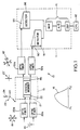
- the optic system 10, shown in Figure 1 includes a sensor 19, illustrated in Figure 2, which generates first and second optical signals which are processed in an opto-electronic interface 11 to extract a fundamental frequency and/or phase which are analyzed in a central processing unit (CPU) 42 to indicate the current pressure and temperature of an environment in which the sensor 19 is located.
- CPU central processing unit
- the optic system 10 shown in Figure 1 utilizes a broad band light spectrum, such as illustrated by curve 16, generated by source 14, such as a light emitting diode.
- the broad band light spectrum which is randomly polarized as depicted by 18, is transmitted through fiber optic cables 20 a and 20 b to entrance connector 21 of sensor 19.
- the randomly polarized light presented to the connector 21 is communicated to a linear polarizer 22 in sensor 19.
- the light spectrum After passing through the linear polarizer 22, the light spectrum has a single plane of polarization, as depicted by 23.
- the linear polarizer 22 is connected to crystal member 30 to simultaneously present identical polarized light waves to a first entrance face 38 of a first waveguide 32 and a second entrance face 40 of a second waveguide 34.
- first and second output waves are modulated and after passing through first 48 and second 50 exit faces are communicated to a second linear polarizer 46.
- the second linear polarizer 46 analyzes the first and second output light waves as depicted by 18' into first 116 and second 116' light spectrums shown in Figure 6.
- the first 116 and second 116' light spectrums are carried by optic cables 52 a and 52 b to the opto-electronic interface 11 where prisms 90 and 95 direct the first 116 and second 116' light spectrums onto a lens grating assembly for focusing onto an array of photodetectors or a charge coupled detector device 91 and 96.
- the output of the detector devices 91 and 96 are presented to conditioning electronics 41 including a MUX, A/D, and DSP, where separate serial voltage streams are generated for the first 116 and second 116' light spectrums.
- the serial voltage streams are analyzed in the conditioning electronics 41 where the frequency and phase difference between the streams and mean frequency and/or phase are determined to indicate the current pressure and temperature in the environment wherein sensor 19 is located and communicated to a host CPU 42.
- the accuracy of the information extracted from the first 116 and second 116' light spectrums by the CPU 42 is dependent on the sensor 19, the particular structure of crystal member 30 and the design of the opto-electronic interface 11.
- the sensor 19, as shown in Figure 2, includes a housing 56 which retains the first 22 and second 46 linear polarizers, crystal member 30 and inter connecting optic fibers 20 a , 20 b , 52 a and 52 b .
- the housing 56 has a cavity therein which is divided into a first chamber 58 and a second chamber 60 by the crystal member 30.
- a first seal 62 located in a groove 64 of housing 56 engages the first waveguide 32 and a second seal 66 located in groove 68 which prevents fluid communication between chambers 58 and 60.
- the crystal member 30 of sensor 19 can be considered as a diaphragm rigidly supported and selectively displaced by a pressure differential between chambers 58 and 60.
- the first 32 and second 34 waveguides associated with crystal member 30 are subjected to the same bending stress induced on crystal member 30 by the pressure differential and being located on opposite sides or the top and bottom of core 36 function as beams.
- the magnitude of stress will be the same but of opposite signs, that is one waveguide will be in tension while the other waveguide will be in compression, as shown in Figure 5.
- crystal member 30 is made up of core member 36 with first 32 and second 34 waveguides attached thereto, see Figure 2 and 3.
- the core 36 is made of yttrium aluminum garnet (Y 3 Al 5 O 12 ) which has a lattice constant a 1 while the first 32 and second 34 waveguides are made of holmium aluminum garnet (Ho 3 Al 5 O 12 ) which has a different uniform lattice constant a 2 , as shown in Figure 4.
- the difference or mismatch of the lattice constants creates a strain which in turn results in a stress.
- the stress is defined by E, Youngs Modulus, and the induced strain.
- the strain in the first 32 and second 34 waveguides has been calculated and measured to be about 0.032%.
- This inherent stress induces birefringence into the first 32 and second 34 waveguides. It is this stress-induced birefringence that causes the fringe pattern shown in Figure 6 and it is the change in the fringe pattern as a function of pressure and temperature that is used to measure the pressure and temperature of the environment.
- first 32 and second 34 waveguides completely cover the core 36, however for some applications it may be desirable to limit the width "w" as shown by lines 70 and 70', shown in Figure 3, and clad the first 32 and second 34 waveguides in the core member 36.
- first 32 and 34 waveguides could also be made from other materials which also have a functional equivalent lattice structure such as: (Tb,Lu) 3 Al 5 O 12 ; (Tb,Yb) 3 Al 5 O 12 ; (Tb,Tm) 3 Al 5 O 12 ; (Tb,Er) 3 Al 5 O 12 ; (Tb,Er) 3 Al 5 O 12 ; (Dy,Lu) 3 Al 5 O 12 ; (Dy,Yb) 3 Al 5 O 12 ; (Dy,Tm) 3 Al 5 O 12 ; (Dy,Er) 3 Al 5 O 12 ; (Gd,Lu) 3 Al 5 O 12 ; (Gd,Yb) 3 Al 5 O 12 ; (Gd,Tm) 3 Al 5 O 12 ; (Gd Er) 3 Al 5 O 12 ; (Y,Lu) 3 (Sc,Al) 5 O 12; (Y,Yb) 3 (Sc,Al) 5 O 12 ; (Y,Tm) 3
- the pressure differential that develops across crystal member 30 acts on, deforms and places a stress on the first 32 and second 34 waveguides in a manner as illustrated by the force diagram shown in Figure 5.
- a first pressure for instance atmospheric pressure
- P x an unknown pressure
- the resulting pressure differential acts on the crystal member 30 to cause a contraction on the top surface and an expansion on the bottom surface which theoretically decreases the length of the top waveguide 32 and increases the length of the bottom waveguide 34.
- these length changes are negligible and can be disregarded.
- the tangential stress that is introduced into crystal member 30 varies as a function of the unknown pressure (P x ) and can be expressed according to the following equation: where:
- the stress induced into the first 32 and second 34 waveguides has an effect on the fringe pattern of the first 116 and second 116' light spectrums which can be expressed as follows:
- the operation of the optic system 10 with a sensor 19 located in an environment where conditions are to be monitored and connected to the opto-electronic interface 11 by optic fibers 52 a and 52 b is as follows:
- the broad band light spectrum from source 14 is communicated through fiber optic cables 20 a and 20 b to sensor 19 where the light waves are polarized and simultaneously communicated to the first 38 and second 40 entrance faces of the first 32 and second 34 waveguides.
- the unknown pressure P X in the environment is communicated to chamber 60 and creates a pressure differential with the pressure P 1 in chamber 58.
- This pressure differential acts on the first 32 and second 34 waveguides to modify the light waves as they pass through the waveguides to create first and second output light waves that are communicated from the first 48 and second 50 exit faces to polarizer 46 and thereafter carried by optic cables 52 a and 52 b to the opto-electronic interface 11.
- the first and second output light waves are subjected to the same conditions of the environment by the bending stress induced on the first 32 and second 34 waveguides except one is positive and the other is negative.
- the output light waves are decomposed into their spectral components which are focused onto the array of linear photodetectors or CCD array(s) 91 and 96 and converted into separate first and second serial voltage streams.
- a critical function of the opto-electronic interface 11 is that each of the first and second output light waves must be read at the same time to develop meaningful information. If the first and second lightwaves are not read over the same interval of time the reading could be corrupted by dynamic changes in the differential pressure.
- the first and second serial voltage streams are converted into a digital format by the conditioning electronics 41 where a time domain to frequency domain transformation is performed to determine the fundamental frequency of the first and second serial voltage streams and difference in the relative phase at those frequencies, this type function is generically referred to as a Fast Fourier Transformation. Thereafter, the difference between the fundamental frequencies and difference in the phase are determined.
Landscapes
- Physics & Mathematics (AREA)
- General Physics & Mathematics (AREA)
- Measuring Temperature Or Quantity Of Heat (AREA)
- Measuring Fluid Pressure (AREA)
Claims (3)
- Optisches Sensorsystem (10) mit einem Kristallglied (30), das von Trägermitteln (56) festgehalten wird und so eine erste Kammer (58) bildet, die mit einem ersten Fluiddruck in Verbindung steht, und eine zweite Kammer (60), die mit einem zweiten, unbekannten, dem Fluiddruck des Umgebungsmilieus entsprechenden Fluiddruck in Verbindung steht, sowie mit Mitteln zur Übertragung von polarisierten Lichtwellen aus einer Quelle (14) durch erste (32) und zweite (34) Wellenleiter zu dem Kristallglied (30), wobei die polarisierten Lichtwellen durch das Kristallglied (30) so modifiziert werden, daß erste und zweite Ausgangswellen entstehen und Istbedingungen in einem Milieu erhalten werden, wobei das optische Sensorsystem (10) dadurch gekennzeichnet ist, daß das Kristallglied (30) ein Substrat (36) mit einem damit eine Einheit bildenden ersten Wellenleiter (32) auf einer oberen Fläche sowie einem mit dem Substrat eine Einheit bildenden zweiten Wellenleiter (34) auf einer unteren Fläche aufweist, wobei der erste Wellenleiter (32) eine erste Eintrittsfläche (38) zum Empfang von polarisierten Lichtwellen aus der Quelle (14) und eine erste Austrittsfläche (48) aufweist und der zweite Wellenleiter (34) eine zweite Eintrittsfläche (40) zum Empfang von polarisierten Lichtwellen aus der Quelle (14) und eine zweite Austrittsfläche (50) aufweist, wobei die zweite Kammer (60) den zweiten unbekannten Druck aufnimmt und so eine Druckdifferenz gegenüber dem ersten Druck in der ersten Kammer (58) entsteht, die auf die obere und die untere Fläche des Kristallglieds (30) einwirkt und so eine Kraft erzeugt, durch die die ersten (32) und zweiten (34) Wellenleiter deformiert werden, und dementsprechend durch die Deformierung der ersten (32) und zweiten (34) Wellenleiter die polarisierten Lichtwellen modifiziert werden und so die ersten Ausgangswellen in dem ersten Wellenleiter (32) und die zweien Ausgangswellen in dem zweiten Wellenleiter (34) erzeugen, wobei die ersten und zweiten Ausgangswellen erste (116) und zweite (116') Interferenzstreifenbilder aufweisen, wobei die ersten Ausgangswellen von der ersten Austrittsfläche (48) her und die zweiten Ausgangswellen von der zweiten Austrittsfläche her (50) zu einer optischen Schnittstelle (11) übertragen werden, die eine regelmäßige Anordnung von linearen Photodetektoren (96, 91) zur Umsetzung der ersten (116) und zweiten (116') Interferenzstreifenbilder in entsprechende erste und zweite Ströme von Serienspannungssignalen aufweist, wobei die ersten und zweiten Ströme von Serienspannungssignalen zu zur Ermittlung von ersten und zweiten Grundfrequenzen und relativen Phasen sowie zur Ermittlung der mittleren Frequenz und Phase der ersten und zweiten Ströme von Serienspannungssignalen geeigneten Prozessoreinrichtungen (41) übertragen werden, wobei der Prozessor zur Ableitung des unbekannten Druckes aus Unterschieden zwischen den Grundfrequenzen und der Phase der ersten und zweiten Ströme von Serienspannungssignalen sowie zur Ableitung der Isttemperatur des Milieus aus der mittleren Frequenz und Phase, bezogen auf eine Bezugsfrequenz, geeignet ist.
- Sensoreinrichtung nach Anspruch 1, bei der der Kern (36) des Kristallgliedes (30) dadurch gekennzeichnet ist, daß er aus Y3Al5O12 gefertigt ist, und die ersten (32) und zweiten (34) Wellenleiter dadurch gekennzeichnet sind, daß sie aus einem Material aus der Reihe Ho3Al5O12;
(Tb,Lu)3Al5O12; (Tb,Yb)3Al5O12; (Tb,Tm)3Al5O12;
(Tb,Er)3Al5O12; (Tb,Er)3Al5O12; (Dy,Lu)3Al5O12;
(Dy,Yb)3Al5O12; (Dy,Tm)3Al5O12; (Dy,Er)3Al5O12;
(Gd,Lu)3Al5O12; (Gd,Yb)3Al5O12; (Gd,Tm)3Al5O12;
(Gd,Er)3Al5O12; (Y,Lu)3(Sc,Al)5O12; (Y,Yb)3(Sc,Al)5O12;
(Y,Tm)3(Sc,Al)5O12; (Y,Er)3(Sc,Al)5O12;
(Dy,Lu)3(Sc,Al)5O12; (Dy,Yb)3(Sc,Al)5O12 ;
(Dy,Tm)3(Sc,Al)5O12; (Dy, Er)3(Sc,Al)5O12;
(Tb,Lu)3(Sc,Al)5O12; (Tb,Yb)3(Sc,Al)5O12;
(Tb,Tm)3(Sc,Al)5O12; (Tb,Er)3(Sc,Al)5O12;
(Gd,Lu)3(Sc,Al)5O12; (Gd,Yb)3(Sc,Al)5O12;
(Gd,Tm)3(Sc,Al)5O12; (Gd,Er)3(Sc,Al)5O12;
(Ca,Tb)3(Si,Al)5O12; (Ca,Dy)3(Si,Al)5O12;
(Ca,Gd)3(Si,Al)5O12; (Ca,Y)3(Si,Sc,Al)5O12;
(Ca,Dy)3(Si,Sc,Al)5O12; (Ca,Tb)3(Si,Sc,Al)5O12;
(Ca,Gd)3(Si,Sc,Al)5O12; (Ca,Lu)3(Ge,Al)5O12;
(Ca,Yb)3(Ge,Al)5O12; (Ca,Tm)3(Ge,Al)5O12; und
(Ca,Er)3(Ge,Al)5O12 gefertigt sind. - Sensoreinrichtung nach Anspruch 2, bei der der Kern (36) und die ersten (32) und zweiten (34) Wellenleiter des Kristallgliedes (30) eine Gitteraufbaudifferenz aufweisen, durch die eine Anfangsdoppelbrechung von etwa 1 × 10⁻³ bei der Betriebswellenlänge erzeugt wird.
Applications Claiming Priority (3)
| Application Number | Priority Date | Filing Date | Title |
|---|---|---|---|
| US915443 | 1992-07-17 | ||
| US07/915,443 US5289720A (en) | 1992-07-17 | 1992-07-17 | Optic sensor for determining environmental conditions |
| PCT/US1993/001129 WO1994002816A1 (en) | 1992-07-17 | 1993-02-09 | Optic sensor for determining environmental conditions |
Publications (2)
| Publication Number | Publication Date |
|---|---|
| EP0650585A1 EP0650585A1 (de) | 1995-05-03 |
| EP0650585B1 true EP0650585B1 (de) | 1996-12-18 |
Family
ID=25435750
Family Applications (1)
| Application Number | Title | Priority Date | Filing Date |
|---|---|---|---|
| EP93904986A Expired - Lifetime EP0650585B1 (de) | 1992-07-17 | 1993-02-09 | Optischer sensor zur bestimmung von druck und temperatur |
Country Status (5)
| Country | Link |
|---|---|
| US (1) | US5289720A (de) |
| EP (1) | EP0650585B1 (de) |
| JP (1) | JPH07509064A (de) |
| DE (1) | DE69306788D1 (de) |
| WO (1) | WO1994002816A1 (de) |
Families Citing this family (8)
| Publication number | Priority date | Publication date | Assignee | Title |
|---|---|---|---|---|
| US5589931A (en) * | 1995-03-17 | 1996-12-31 | Alliedsignal Inc. | System to determine environmental pressure and birefringent-biased cladded optical sensor for use therein |
| US5561522A (en) * | 1995-03-27 | 1996-10-01 | Alliedsignal Inc. | Integrated birefringent-biased pressure and temperature sensor system |
| US5694205A (en) * | 1995-10-19 | 1997-12-02 | Alliedsignal Inc. | Birefringent-biased sensor having temperature compensation |
| US20040047536A1 (en) * | 2002-09-05 | 2004-03-11 | Pickrell Gary R. | Creep and viscous flow resistant fiber optic sensor |
| US6776522B2 (en) * | 2002-10-09 | 2004-08-17 | Steven J. Syracuse | Apparatus and system for monitoring temperature of high voltage conductors |
| RU2231034C1 (ru) * | 2003-04-25 | 2004-06-20 | Санкт-Петербургский государственный горный институт им. Г.В. Плеханова (Технический университет) | Индикатор давления |
| WO2009006944A1 (en) * | 2007-07-12 | 2009-01-15 | Abb Research Ltd | Pressure sensor |
| EP4308696A1 (de) | 2021-03-16 | 2024-01-24 | ApiRays Bioscience AB | Modifizierte shigella-apyrase und verwendungen davon |
Family Cites Families (10)
| Publication number | Priority date | Publication date | Assignee | Title |
|---|---|---|---|---|
| US3950987A (en) * | 1975-05-13 | 1976-04-20 | Isaak Isaevich Slezinger | Piezo-optic measuring transducer and accelerometer, pressure gauge, dynamometer, and thermometer based thereon |
| US4367040A (en) * | 1979-05-29 | 1983-01-04 | Tokyo Shibaura Denki Kabushiki Kaisha | Multi-channel optical sensing system |
| US4466295A (en) * | 1982-09-20 | 1984-08-21 | Trw Inc. | Photoelastic sensing means |
| US4495411A (en) * | 1982-10-27 | 1985-01-22 | The United States Of America As Represented By The Secretary Of The Navy | Fiber optic sensors operating at DC |
| US4495819A (en) * | 1982-12-23 | 1985-01-29 | Gould Inc. | Optical pressure sensor |
| DE3341845A1 (de) * | 1983-11-19 | 1985-05-30 | Philips Patentverwaltung Gmbh, 2000 Hamburg | Optische druckmessvorrichtung |
| JPS622130A (ja) * | 1985-06-27 | 1987-01-08 | Sharp Corp | 応力検知装置 |
| DE3541733C1 (de) * | 1985-11-26 | 1986-11-20 | Fraunhofer-Gesellschaft zur Förderung der angewandten Forschung e.V., 8000 München | Faseroptische Fabry-Perot-Einrichtung |
| US4932263A (en) * | 1989-06-26 | 1990-06-12 | General Motors Corporation | Temperature compensated fiber optic pressure sensor |
| US5187983A (en) * | 1991-09-04 | 1993-02-23 | Universite Du Quebec A Hull | Fiber-optic strain gauge manometer |
-
1992
- 1992-07-17 US US07/915,443 patent/US5289720A/en not_active Expired - Fee Related
-
1993
- 1993-02-09 EP EP93904986A patent/EP0650585B1/de not_active Expired - Lifetime
- 1993-02-09 JP JP6503982A patent/JPH07509064A/ja active Pending
- 1993-02-09 DE DE69306788T patent/DE69306788D1/de not_active Expired - Lifetime
- 1993-02-09 WO PCT/US1993/001129 patent/WO1994002816A1/en not_active Ceased
Also Published As
| Publication number | Publication date |
|---|---|
| JPH07509064A (ja) | 1995-10-05 |
| EP0650585A1 (de) | 1995-05-03 |
| US5289720A (en) | 1994-03-01 |
| DE69306788D1 (de) | 1997-01-30 |
| WO1994002816A1 (en) | 1994-02-03 |
Similar Documents
| Publication | Publication Date | Title |
|---|---|---|
| EP0007312B1 (de) | Optisches messgerät | |
| EP0098875B1 (de) | Interferometermatrix mit optischer faser mit quadratur | |
| US6335524B1 (en) | High speed demodulation systems for fiber optic grating sensors | |
| Porte et al. | Imbalanced Mach-Zehnder interferometer integrated in micromachined silicon substrate for pressure sensor | |
| US20080212917A1 (en) | Fiber Optic Temperature and Pressure Sensor and System Incorporating Same | |
| US5694205A (en) | Birefringent-biased sensor having temperature compensation | |
| US4882716A (en) | Optic fiber hydrophone and antenna associating a series of hydrophones | |
| EP0614520B1 (de) | Doppelbrechender temperaturfühler | |
| Hongo et al. | Applications of fiber Bragg grating sensors and high‐speed interrogation techniques | |
| US4709145A (en) | Method and apparatus for compensating fiber optic lead and connector losses in a fiber optic sensor by using a dual wavelength optical source and matched polarizer | |
| US4822135A (en) | Optical wave guide band edge sensor and method | |
| NL8402801A (nl) | In temperatuur gecompenseerde optische druksensor. | |
| US20090290147A1 (en) | Dynamic polarization based fiber optic sensor | |
| EP1405043B1 (de) | Differenzmesssystem auf der basis der benutzung von paaren von bragg-gittern | |
| EP0650585B1 (de) | Optischer sensor zur bestimmung von druck und temperatur | |
| US5410917A (en) | Optical force sensor for high density planar electrical interconnects | |
| US5561522A (en) | Integrated birefringent-biased pressure and temperature sensor system | |
| US5589931A (en) | System to determine environmental pressure and birefringent-biased cladded optical sensor for use therein | |
| US5317524A (en) | Spectral signal analyzer system | |
| Kojima et al. | High-speed optical wavelength interrogator using a PLC-type optical filter for fiber Bragg grating sensors | |
| JP2003270041A (ja) | 高速波長検出装置 | |
| US6270254B1 (en) | Extended range fiber-optic temperature sensor | |
| WO1997043614A1 (en) | An optical pressure sensing system and a birefringent sensor for use therein | |
| Davis | Fiberoptic sensors: an overview | |
| Ohkawa et al. | Integrated optic micropressure sensor using ring resonator |
Legal Events
| Date | Code | Title | Description |
|---|---|---|---|
| PUAI | Public reference made under article 153(3) epc to a published international application that has entered the european phase |
Free format text: ORIGINAL CODE: 0009012 |
|
| 17P | Request for examination filed |
Effective date: 19950109 |
|
| AK | Designated contracting states |
Kind code of ref document: A1 Designated state(s): DE FR GB |
|
| GRAG | Despatch of communication of intention to grant |
Free format text: ORIGINAL CODE: EPIDOS AGRA |
|
| 17Q | First examination report despatched |
Effective date: 19960326 |
|
| GRAH | Despatch of communication of intention to grant a patent |
Free format text: ORIGINAL CODE: EPIDOS IGRA |
|
| GRAH | Despatch of communication of intention to grant a patent |
Free format text: ORIGINAL CODE: EPIDOS IGRA |
|
| GRAA | (expected) grant |
Free format text: ORIGINAL CODE: 0009210 |
|
| AK | Designated contracting states |
Kind code of ref document: B1 Designated state(s): DE FR GB |
|
| REF | Corresponds to: |
Ref document number: 69306788 Country of ref document: DE Date of ref document: 19970130 |
|
| ET | Fr: translation filed | ||
| PG25 | Lapsed in a contracting state [announced via postgrant information from national office to epo] |
Ref country code: DE Effective date: 19970319 |
|
| PLBE | No opposition filed within time limit |
Free format text: ORIGINAL CODE: 0009261 |
|
| STAA | Information on the status of an ep patent application or granted ep patent |
Free format text: STATUS: NO OPPOSITION FILED WITHIN TIME LIMIT |
|
| 26N | No opposition filed | ||
| REG | Reference to a national code |
Ref country code: GB Ref legal event code: IF02 |
|
| PGFP | Annual fee paid to national office [announced via postgrant information from national office to epo] |
Ref country code: GB Payment date: 20030106 Year of fee payment: 11 |
|
| PGFP | Annual fee paid to national office [announced via postgrant information from national office to epo] |
Ref country code: FR Payment date: 20030204 Year of fee payment: 11 |
|
| PG25 | Lapsed in a contracting state [announced via postgrant information from national office to epo] |
Ref country code: GB Free format text: LAPSE BECAUSE OF NON-PAYMENT OF DUE FEES Effective date: 20040209 |
|
| GBPC | Gb: european patent ceased through non-payment of renewal fee |
Effective date: 20040209 |
|
| PG25 | Lapsed in a contracting state [announced via postgrant information from national office to epo] |
Ref country code: FR Free format text: LAPSE BECAUSE OF NON-PAYMENT OF DUE FEES Effective date: 20041029 |
|
| REG | Reference to a national code |
Ref country code: FR Ref legal event code: ST |
|
| P01 | Opt-out of the competence of the unified patent court (upc) registered |
Effective date: 20230525 |