EP0649663A1 - Single needle recirculation system for harvesting blood components - Google Patents
Single needle recirculation system for harvesting blood components Download PDFInfo
- Publication number
- EP0649663A1 EP0649663A1 EP94305976A EP94305976A EP0649663A1 EP 0649663 A1 EP0649663 A1 EP 0649663A1 EP 94305976 A EP94305976 A EP 94305976A EP 94305976 A EP94305976 A EP 94305976A EP 0649663 A1 EP0649663 A1 EP 0649663A1
- Authority
- EP
- European Patent Office
- Prior art keywords
- blood
- return
- cycle
- during
- bag
- Prior art date
- Legal status (The legal status is an assumption and is not a legal conclusion. Google has not performed a legal analysis and makes no representation as to the accuracy of the status listed.)
- Ceased
Links
Images

Classifications
-
- A—HUMAN NECESSITIES
- A61—MEDICAL OR VETERINARY SCIENCE; HYGIENE
- A61M—DEVICES FOR INTRODUCING MEDIA INTO, OR ONTO, THE BODY; DEVICES FOR TRANSDUCING BODY MEDIA OR FOR TAKING MEDIA FROM THE BODY; DEVICES FOR PRODUCING OR ENDING SLEEP OR STUPOR
- A61M1/00—Suction or pumping devices for medical purposes; Devices for carrying-off, for treatment of, or for carrying-over, body-liquids; Drainage systems
- A61M1/14—Dialysis systems; Artificial kidneys; Blood oxygenators ; Reciprocating systems for treatment of body fluids, e.g. single needle systems for hemofiltration or pheresis
- A61M1/30—Single needle dialysis ; Reciprocating systems, alternately withdrawing blood from and returning it to the patient, e.g. single-lumen-needle dialysis or single needle systems for hemofiltration or pheresis
-
- A—HUMAN NECESSITIES
- A61—MEDICAL OR VETERINARY SCIENCE; HYGIENE
- A61M—DEVICES FOR INTRODUCING MEDIA INTO, OR ONTO, THE BODY; DEVICES FOR TRANSDUCING BODY MEDIA OR FOR TAKING MEDIA FROM THE BODY; DEVICES FOR PRODUCING OR ENDING SLEEP OR STUPOR
- A61M1/00—Suction or pumping devices for medical purposes; Devices for carrying-off, for treatment of, or for carrying-over, body-liquids; Drainage systems
- A61M1/02—Blood transfusion apparatus
- A61M1/0209—Multiple bag systems for separating or storing blood components
-
- A—HUMAN NECESSITIES
- A61—MEDICAL OR VETERINARY SCIENCE; HYGIENE
- A61M—DEVICES FOR INTRODUCING MEDIA INTO, OR ONTO, THE BODY; DEVICES FOR TRANSDUCING BODY MEDIA OR FOR TAKING MEDIA FROM THE BODY; DEVICES FOR PRODUCING OR ENDING SLEEP OR STUPOR
- A61M1/00—Suction or pumping devices for medical purposes; Devices for carrying-off, for treatment of, or for carrying-over, body-liquids; Drainage systems
- A61M1/14—Dialysis systems; Artificial kidneys; Blood oxygenators ; Reciprocating systems for treatment of body fluids, e.g. single needle systems for hemofiltration or pheresis
- A61M1/30—Single needle dialysis ; Reciprocating systems, alternately withdrawing blood from and returning it to the patient, e.g. single-lumen-needle dialysis or single needle systems for hemofiltration or pheresis
- A61M1/301—Details
- A61M1/303—Details having a reservoir for treated blood to be returned
-
- A—HUMAN NECESSITIES
- A61—MEDICAL OR VETERINARY SCIENCE; HYGIENE
- A61M—DEVICES FOR INTRODUCING MEDIA INTO, OR ONTO, THE BODY; DEVICES FOR TRANSDUCING BODY MEDIA OR FOR TAKING MEDIA FROM THE BODY; DEVICES FOR PRODUCING OR ENDING SLEEP OR STUPOR
- A61M1/00—Suction or pumping devices for medical purposes; Devices for carrying-off, for treatment of, or for carrying-over, body-liquids; Drainage systems
- A61M1/14—Dialysis systems; Artificial kidneys; Blood oxygenators ; Reciprocating systems for treatment of body fluids, e.g. single needle systems for hemofiltration or pheresis
- A61M1/30—Single needle dialysis ; Reciprocating systems, alternately withdrawing blood from and returning it to the patient, e.g. single-lumen-needle dialysis or single needle systems for hemofiltration or pheresis
- A61M1/301—Details
- A61M1/305—Control of inversion point between collection and re-infusion phase
- A61M1/306—Pressure control, e.g. using substantially rigid closed or gas buffered or elastic reservoirs
-
- A—HUMAN NECESSITIES
- A61—MEDICAL OR VETERINARY SCIENCE; HYGIENE
- A61M—DEVICES FOR INTRODUCING MEDIA INTO, OR ONTO, THE BODY; DEVICES FOR TRANSDUCING BODY MEDIA OR FOR TAKING MEDIA FROM THE BODY; DEVICES FOR PRODUCING OR ENDING SLEEP OR STUPOR
- A61M1/00—Suction or pumping devices for medical purposes; Devices for carrying-off, for treatment of, or for carrying-over, body-liquids; Drainage systems
- A61M1/36—Other treatment of blood in a by-pass of the natural circulatory system, e.g. temperature adaptation, irradiation ; Extra-corporeal blood circuits
- A61M1/3601—Extra-corporeal circuits in which the blood fluid passes more than once through the treatment unit
- A61M1/3603—Extra-corporeal circuits in which the blood fluid passes more than once through the treatment unit in the same direction
-
- A—HUMAN NECESSITIES
- A61—MEDICAL OR VETERINARY SCIENCE; HYGIENE
- A61M—DEVICES FOR INTRODUCING MEDIA INTO, OR ONTO, THE BODY; DEVICES FOR TRANSDUCING BODY MEDIA OR FOR TAKING MEDIA FROM THE BODY; DEVICES FOR PRODUCING OR ENDING SLEEP OR STUPOR
- A61M1/00—Suction or pumping devices for medical purposes; Devices for carrying-off, for treatment of, or for carrying-over, body-liquids; Drainage systems
- A61M1/36—Other treatment of blood in a by-pass of the natural circulatory system, e.g. temperature adaptation, irradiation ; Extra-corporeal blood circuits
- A61M1/3621—Extra-corporeal blood circuits
- A61M1/3643—Priming, rinsing before or after use
- A61M1/3644—Mode of operation
-
- A—HUMAN NECESSITIES
- A61—MEDICAL OR VETERINARY SCIENCE; HYGIENE
- A61M—DEVICES FOR INTRODUCING MEDIA INTO, OR ONTO, THE BODY; DEVICES FOR TRANSDUCING BODY MEDIA OR FOR TAKING MEDIA FROM THE BODY; DEVICES FOR PRODUCING OR ENDING SLEEP OR STUPOR
- A61M1/00—Suction or pumping devices for medical purposes; Devices for carrying-off, for treatment of, or for carrying-over, body-liquids; Drainage systems
- A61M1/36—Other treatment of blood in a by-pass of the natural circulatory system, e.g. temperature adaptation, irradiation ; Extra-corporeal blood circuits
- A61M1/3693—Other treatment of blood in a by-pass of the natural circulatory system, e.g. temperature adaptation, irradiation ; Extra-corporeal blood circuits using separation based on different densities of components, e.g. centrifuging
- A61M1/3696—Other treatment of blood in a by-pass of the natural circulatory system, e.g. temperature adaptation, irradiation ; Extra-corporeal blood circuits using separation based on different densities of components, e.g. centrifuging with means for adding or withdrawing liquid substances during the centrifugation, e.g. continuous centrifugation
-
- A—HUMAN NECESSITIES
- A61—MEDICAL OR VETERINARY SCIENCE; HYGIENE
- A61M—DEVICES FOR INTRODUCING MEDIA INTO, OR ONTO, THE BODY; DEVICES FOR TRANSDUCING BODY MEDIA OR FOR TAKING MEDIA FROM THE BODY; DEVICES FOR PRODUCING OR ENDING SLEEP OR STUPOR
- A61M1/00—Suction or pumping devices for medical purposes; Devices for carrying-off, for treatment of, or for carrying-over, body-liquids; Drainage systems
- A61M1/36—Other treatment of blood in a by-pass of the natural circulatory system, e.g. temperature adaptation, irradiation ; Extra-corporeal blood circuits
- A61M1/3621—Extra-corporeal blood circuits
- A61M1/3643—Priming, rinsing before or after use
-
- A—HUMAN NECESSITIES
- A61—MEDICAL OR VETERINARY SCIENCE; HYGIENE
- A61M—DEVICES FOR INTRODUCING MEDIA INTO, OR ONTO, THE BODY; DEVICES FOR TRANSDUCING BODY MEDIA OR FOR TAKING MEDIA FROM THE BODY; DEVICES FOR PRODUCING OR ENDING SLEEP OR STUPOR
- A61M2202/00—Special media to be introduced, removed or treated
- A61M2202/04—Liquids
- A61M2202/0413—Blood
- A61M2202/0415—Plasma
-
- A—HUMAN NECESSITIES
- A61—MEDICAL OR VETERINARY SCIENCE; HYGIENE
- A61M—DEVICES FOR INTRODUCING MEDIA INTO, OR ONTO, THE BODY; DEVICES FOR TRANSDUCING BODY MEDIA OR FOR TAKING MEDIA FROM THE BODY; DEVICES FOR PRODUCING OR ENDING SLEEP OR STUPOR
- A61M2202/00—Special media to be introduced, removed or treated
- A61M2202/04—Liquids
- A61M2202/0413—Blood
- A61M2202/0427—Platelets; Thrombocytes
-
- A—HUMAN NECESSITIES
- A61—MEDICAL OR VETERINARY SCIENCE; HYGIENE
- A61M—DEVICES FOR INTRODUCING MEDIA INTO, OR ONTO, THE BODY; DEVICES FOR TRANSDUCING BODY MEDIA OR FOR TAKING MEDIA FROM THE BODY; DEVICES FOR PRODUCING OR ENDING SLEEP OR STUPOR
- A61M2205/00—General characteristics of the apparatus
- A61M2205/12—General characteristics of the apparatus with interchangeable cassettes forming partially or totally the fluid circuit
Landscapes
- Health & Medical Sciences (AREA)
- Heart & Thoracic Surgery (AREA)
- Vascular Medicine (AREA)
- Hematology (AREA)
- Engineering & Computer Science (AREA)
- Anesthesiology (AREA)
- Biomedical Technology (AREA)
- Urology & Nephrology (AREA)
- Life Sciences & Earth Sciences (AREA)
- Animal Behavior & Ethology (AREA)
- General Health & Medical Sciences (AREA)
- Public Health (AREA)
- Veterinary Medicine (AREA)
- Emergency Medicine (AREA)
- Cardiology (AREA)
- External Artificial Organs (AREA)
Abstract
A single needle system for withdrawing donated blood, processing the blood to harvest components such as platelets, and returning processed blood to the donor through the single needle (10). Processing is performed by a centrifuge (24) which separates blood components into stratified layers with a buffy coat containing platelets and white blood cells stably interfacing a red blood cell layer. Blood is withdrawn during a draw cycle and returned to the donor during a return cycle. A recirculation system is provided so that blood flows at a reduced rate through the processing system during the return cycle in order to minimize return cycle time while maintaining the stable position of the interface between buffy coat and red blood cell layers. A storage bag (37) receives processed blood during the draw cycle and blood is squeezed from the bag (37) during the return cycle, a portion returned to the donor and another portion entering the recirculation path (35,37',38). A pressure sensor (40) is located in the return path (35,37',38) to indicate an empty storage bag (37) upon a precipitous drop in pressure. In that manner an immediate switch to the draw cycle is made to further minimize return cycle time. To still further minimize the return cycle time, flow resistance in the return path (35,37',38) is minimized with more than 80% of the flow resistance in the return path associated with the needle (10).
Description
- This invention relates to harvesting blood components from a donor by processing the donated blood and returning it to the donor through the same needle from which it was withdrawn.
- Donated blood is typically processed by withdrawing it through a needle and sending it through a disposable tubing set to a centrifuge in order to separate the blood into its various components. The centrifugal apparatus is fitted with a disposable plastic vessel through which the blood is circulated. The vessel is fitted into a centrifuge bowl that is driven by a motor. An exemplary vessel is a circumferential separation channel having several outlets positioned at different radial positions within the channel in order to remove blood components separated into stratified layers of differing density by the centrifuge. Red blood cells (RBC), being the most dense of the components, are packed within the channel at the most radially outward location, whereas the stratified layer of plasma is at the most radially inward location. A relatively thin, yellowish layer, called the buffy coat, contains white blood cells and platelets and is located between the red blood cell layer and the plasma layer. Within the buffy coat, the platelets are stratified toward the plasma, while the white blood cells are stratified toward the red blood cells.
- U.S. Patent No. 4,708,712, incorporated herein by reference, describes a two-stage separation channel for collecting platelets separately from white blood cells and also having an outlet for collecting source plasma. The red and white blood cells are returned to the donor, along with most of the plasma.
- In a dual-needle procedure, frequently used with a centrifuge apparatus such as described above, whole blood is removed from the donor through a needle usually positioned in one of the donor's arms. The whole blood is then processed by the centrifugal apparatus and the white and red blood cells are returned to the donor through the tubing set and a needle usually positioned in the other arm. If only platelets are being harvested, more of the plasma is returned as well as the red and white blood cells.
- For the separation channel described in U.S. Patent 4,708,712, the dual-needle procedure is satisfactory for harvesting platelets in a manner that is relatively free from white blood cell contamination. It is, however, a somewhat difficult procedure for the donor since the donor must remain quiet for a significant period of time with needles in both arms.
- In a single-needle process, blood is removed from the donor, processed to collect platelets, and the whole blood, minus the collected platelets and perhaps also minus collected source plasma, is returned to the donor through the same single needle. Platelets are stored in a platelet collection bag, and the plasma is separately collected and stored in a plasma collection bag. Processed blood from which the harvested components have been removed is stored in a separate blood storage return bag during the draw cycle. During the return cycle, a squeezing mechanism places pressure on the external sides of the blood storage bag in order to squeeze the blood from the bag for return to the donor through the single needle. A suitable blood storage bag and pressure mechanism is described in U.S. Patent No. 4,991,743 which is incorporated herein by reference. In the single-needle process, as originally developed, the flow of blood through the centrifuge is halted for a specific period of time while blood is returned to the donor during the return cycle. As a result, blood flow through the centrifuge is intermittent and the interface between the plasma layer and the red blood cell layer shifts, causing significantly greater contamination of the collected platelets with white blood cells. In addition to greater contamination, the efficiency of collecting a significant percentage of the platelets from the donated blood is considerably less than the efficiency of the dual needle procedure. Thus, while the standard single needle intermittent flow procedure is more comfortable for the donor, it has less desirable results in the collection of platelets.
- In order to improve the efficiency of the single-needle procedure and remove the contamination problem, a recirculating loop system has been developed in which the inlet pump is not stopped during the return cycle. Instead, the inlet pump, which pumps whole blood into the separation channel during the draw cycle, continues to operate during the return cycle to recirculate and reprocess blood already in the system. The recirculated blood, together with blood stored in the storage bag, are combined to provide both the recirculation flow to the inlet pump and the return flow to the donor.
- In a prior art recirculation system, the draw cycle is operated for a period sufficient to withdraw and process a specific volume of whole blood from the donor. Once that volume has been obtained, the system is switched to a return cycle by opening a valve in the return line and putting pressure on the storage bag. Blood squeezed from the bag is returned in the reverse direction through the needle into the donor until the bag is essentially emptied, at which time the valve is closed and blood is once again drawn from the donor to the inlet pump. In this system, the instantaneous flow of blood to the donor in the return cycle is regulated in order to limit the amount of anticoagulant solution returned to the donor. To accomplish that end, the speed of the inlet pump is reduced during the return cycle and a programmable restriction valve is placed in the return line. In that manner the recirculation flow is related to the re-infusion flow in order to regulate the re-infusion flow to a desired instantaneous level. The time duration of the return cycle is lengthened to accommodate the need to regulate re-infusion flow and also to improve the efficiency of the process since additional platelets are harvested by reprocessing blood in the return cycle. A lengthy return cycle will reprocess more blood for a given recirculation flow.
- The current invention seeks to maintain undisturbed the RBC interface of the buffy coat in the centrifuge throughout both the draw and return cycles while minimizing the length of time for the return cycle. It has been determined that it is not necessary to regulate the instantaneous flow of anticoagulant back to the donor as long as the average flow of anticoagulant returned over a complete single needle cycle is kept within the tolerance of the donor. As a consequence, a system has been developed in which the recirculation flow and the re-infusion flow are essentially independent during the return cycle. Instead, the recirculation flow is desirably established at as small a fraction as possible of the inlet flow during the draw cycle in order to minimize the duration of the return cycle and still maintain the stability of the interface. The re-infusion flow is regulated primarily by needle size; no restrictions are placed in the return flow line and the return line flow resistance is deliberately minimized.
- By maintaining a stable interface at which the platelets are separated from the blood within the centrifuge, contamination of platelets by white blood cells is reduced to a level that is comparable to or less than that of the double-needle procedure. Platelet collection efficiency is improved by reducing inlet pump speed during the return cycle and thereby achieving an efficiency similar to or above the efficiency of the dual needle procedure.
- While the prior art standard single-needle non-recirculation procedure is comfortable for the donor, the previous procedures can be used efficiently with only about 70% of the donor population. Various physiological considerations determine the maximum practical inlet flow rate -- the size, the weight, the sex, and the hematocrit (red blood cell content) of the donor are important in determining the maximum practical flow rate for removal of blood from the donor by the inlet pump and for effective processing of blood by the centrifuge. The speed of the pump during the draw cycle is established according to those considerations. Since the total time for the procedure may be approximately an hour and 30 minutes, it is desirable to operate at the maximum practical flow rate for the specific donor. For the largest of donors, that may be about 90 milliliters per minute for the double-needle procedure. However, that flow rate corresponds to an average blood processing rate of only about 50 milliliters per minute for the standard non-recirculating single-needle procedure. The ratio, 5/9, is approximately the ratio of the duration of the draw cycle to the total cycle time for draw and return. As mentioned above, a prior art single-needle recirculating procedure desires long return cycles of perhaps even greater duration than 5/9 in order to control the return of anticoagulant. In this invention, it is desired to minimize the return cycle time in order to improve the average blood processing rate for a given inlet pump flow rate and thereby minimize the length of time for a completed donation.
- With the return cycle duration minimized, a lower instantaneous flow rate during the draw cycle is possible for the same blood processing rate. Two additional benefits are achieved thereby: (1) when the instantaneous flow rate is lowered, the cell separation efficiency of the separation channel is increased thereby providing better separation and improved harvesting of the platelets; and (2) as the instantaneous flow rate is decreased, the percentage of the donor population which can be efficiently accommodated by the single-needle procedure is increased to about 98% of the donor population, thus providing the benefits of the single needle system to many more people.
- Briefly stated, the invention achieves the minimization of return cycle time by lowering the speed of the inlet pump during the return cycle, by minimizing flow resistance in the return path, and by instituting a volume/pressure control system. A pressure gauge is placed in the return line and, as blood is squeezed into the return line from the storage bag, pressure is maintained in the return line at a relatively high level. However, as soon as the bag is emptied, the pressure in the return line drops precipitously, indicating that the bag is empty. At that point the system is switched back to a draw cycle.
- Another aspect of the invention is to limit the maximum allowable plasma fraction that can be collected in accordance with the blood processing rate. During the collection of plasma, the recirculation system of the invention requires the recirculation of high-hematocrit blood. Because the separation channel processing efficiency is lowered for high-hematocrit blood, the target hematocrit level in the packed red blood cell (RBC) return line and the allowable plasma collection fraction, are designed as a decreasing function as the blood processing rate increases rather than a constant target and fraction that are independent of the blood processing rate.
- During the start-up phase of the procedure, for a system that is primed with saline, blood displaces the saline that was used to prime and displace air from the tubing set. To minimize the time needed for the start-up phase, recirculation is not performed during the return cycle because the recirculation of saline in the tubing set prolongs the start-up and delays the beginning of platelet collection. For a system that is primed with blood, recirculation can begin as soon as the tubing set is filled with blood.
- The above-mentioned and other features and objects of the invention and the manner of attaining them will become more apparent and the invention itself will best be understood by reference to the following description of embodiments of the invention taken in conjunction with the accompanying drawings, a brief description of which follows.
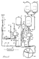
- Figure 1 is a diagram of the recirculation flow in an embodiment of the single-needle recirculation system of the invention.
- Figure 2 shows flow profiles within the draw and return cycles for the embodiment of Fig. 1.
- Figure 3 shows the flow profiles for the previous volume/time standard single needle system with no recirculation.
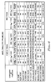
- Figure 4 shows a state table for the start-up phase and the run phase of the recirculating system of the embodiment of Fig. 1.
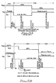
- Figures 5A and 5B are illustrations of start-up protocol. Fig. 5A shows the protocol for a standard single needle system while Fig. 5B shows the protocol for the single needle recirculation system of the embodiment of Fig. 1.
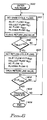
- Figure 6 is a flowchart of the control system used with the embodiment of Fig. 1.
-
- Referring now to the drawing, like numbers indicate like features and the same number appearing in more than one figure refers to the same element.
- Figure 1 shows the recirculation flow within an exemplary system embodying the invention. A
single lumen needle 10 is inserted into a donor for obtaining platelets or both plasma and platelets from the blood of the donor. The needle is connected to a first branch of a Y connector 11. A second branch of the Y connector is connected to theinlet line 12 which passes through aline clamp 13 to amanifold 14. Aconnector 15 is attached to a saline bag (not shown) for introduction of saline liquid throughline 16 tomanifold 14. A connector 17 is attached to an anti-coagulant bag (not shown) for introduction of anti-coagulant solution throughline 18 toanti-coagulant pump 19. The outlet ofpump 19 is connected to the manifold 14 for insertion of a controlled amount of anti-coagulant solution to blood drawn from the donor. It is desirable to minimize the distance betweenmanifold 14 and thesingle needle 10 in order that the anti-coagulant solution can be mixed with the donor's blood as soon as possible in the tubing set of the recirculation system. Blood frommanifold 14 is presented to the inlet side ofinlet pump 21 through line 20 andaccess pressure sensor 28. The outlet side ofinlet pump 21 is connected throughline 22 and adrip chamber 23 to at least one separation vessel. In this exemplary embodiment, the separation vessel is aseparation channel 24. - As discussed above,
plastic separation channel 24 is inserted into the bowl of a centrifuge for separating out the various components of the blood. Plasma is drawn out of the separation channel by theplasma pump 25 over the plasma collectline 26. The plasma is passed through aY connector 27 and is either sent toblood storage bag 37 via lines 27' and 37' or is collected in plasma collectbag 29. Platelets are drawn from theseparation channel 24 overline 30 to thecollect pump 31 and are pumped throughY connector 32 into one or the other of platelet collectbags Y connectors - High-hematocrit blood is drawn from the separation channel through
line 35,Y connector 36, and line 37' to thestorage bag 37. If source plasma is not collected, the plasma in line 27' is combined with the blood inline 35 for storage inbag 37. Thereturn line 38 runs from thestorage bag 37 through thereturn valve 39 to a third branch of the Y connector 11. - During a draw cycle, the
return valve 39 is closed so that the processed blood is accumulated in thestorage bag 37. Platelets are collected in the platelet collectbags bag 29. If it is not desired to collect plasma, the plasma is directed to thestorage bag 37. - During the return cycle, the
return valve 39 is opened and pressure is exerted on thestorage bag 37 to squeeze blood therefrom throughline 38 to the Y connector 11 and from there through theneedle 10 to the donor. A portion of the blood inreturn line 38 is passed through Y connector 11 to theinlet line 12 for presentation to theinlet pump 21. In that manner,inlet pump 21 continues to provide a flow of blood into theseparation channel 24, whether in the draw cycle or in the return cycle. By maintaining the flow of blood to the separation channel, the interface position between the various blood components in the channel is not disturbed when changing from draw cycle to return cycle. By not disturbing the interface, contamination of the platelet collection line with white blood cells is minimized. - During the return cycle, a constant volume of blood remains in the recirculating system which extends from
inlet line 12 through the separation channel, out of the channel throughlines 35 and 37' into thestorage bag 37, out ofbag 37 through thereturn line 38 and Y connector 11 back toinlet line 12. Platelets continue to be collected overline 30, but the volume so collected is made up from thereturn bag 37. The blood being reprocessed in thecentrifuge 24 during the return cycle is mixed with the blood instorage bag 37 for presentation to thereturn line 38. By reprocessing a portion of the blood stored inbag 37, additional platelets not previously removed from the processed blood are collected, thus providing an improvement in the efficiency of platelet collection. - A
return pressure sensor 40 located in return line 27' senses the pressure being exerted on the fluid inbag 37.Sensor 40 can be located at any convenient place in the return system such as inline 38 or associated withstorage bag 37. Once thebag 37 is emptied, thesensor 40 shows a sudden drop in pressure signalling that thebag 37 is empty and that the return cycle can be terminated and the draw cycle begun again. Thepressure sensor 40 is connected to a microprocessor-basedcontrol system 41 for switchingreturn valve 39 to a closed position and resuming the draw cycle as soon as the sudden drop in pressure is sensed. - As mentioned above, two of the significant advantages of the invention are minimizing instantaneous flow rates in order to accommodate a greater percentage of the donor population with the single needle procedure and minimizing the length of time for the donor to be attached to the system. The minimizing of return cycle time accomplishes these ends and is furthered by utilizing the pressure sensing approach. It is also valuable to increase the size of the tubing set in the return path relative to the remainder of the tubing set in order to minimize the resistance to the flow of blood through the return path. That is to say, if the total return flow resistance in the return path includes the flow resistance through the needle, summed with the flow resistance through the remainder of the return path, i.e., the flow resistance associated with the
storage bag 37, the flow resistance associated with the Y connector 11, and the flow resistance of thereturn line 38, it is desirable to provide 80% or more of the total return flow resistance in the needle. In that manner, the return cycle duration is minimized, thus achieving a lower instantaneous flow rate for the same blood processing rate. - Lowering the flow rate of blood through the recirculating system also reduces the duration of the return cycle. To minimize return cycle time, it is desirable to reduce the recirculated flow as low as possible while still maintaining the stability of the interface position between the RBC and the buffy coat. Maintaining stability keeps collected platelet purity high. A low recirculated flow rate improves the efficiency of collecting platelets from the donated blood as well as minimizing return cycle time.
- While the volume of blood in the recirculation path does not change with flow rate, the spring actuated flow controller which squeezes blood from the storage bag must overcome the resistance of the return line to recirculate blood to the inlet pump. By keeping the recirculated flow rate low, a lower percentage of the spring force is used for recirculation leaving a higher percentage of spring force available for returning blood to the donor. In that manner, return cycle duration is minimized by a low recirculation flow rate.
- It should be noted, as stated above, that it is valuable to increase the size of the tubing in the return path in order to minimize the resistance to the flow of blood through the return path. As the resistance of the return path approaches zero, the effect of recirculation flow rates on the return cycle duration also approaches zero, thus optimizing the return cycle duration. However, as noted above, even if the effect of recirculation flow rate on the duration of the return cycle were minimized, a low recirculation flow rate is still desirable to keep platelet collection efficiency high. While theoretically a higher recirculation flow rate would reprocess more blood and thereby obtain more platelets, a buffy coat must be stably maintained to keep platelet collection efficiency high. Since the plasma pump is off during the return cycle, a much greater fraction of the separated plasma is forced out the RBC return line. This adversely affects the flow pattern in the separation channel and has the effect of depleting the buffy coat. Therefore a high recirculation flow rate tends to deplete the buffy coat and thereby reduce platelet collection efficiency. Since recirculated blood is high hematocrit blood, there is also the danger of RBC spillover into the platelet collection bag.
- To summarize, in order to gain the optimal system for realizing the many benefits of a single needle recirculation system, it is desirable to minimize return cycle duration. That is accomplished by reducing the flow resistance of the return path, by using a volume/pressure control, and by lowering the recirculation flow rate while still maintaining a stable interface of stratified layers in the separation channel of the centrifuge.
- When priming the system shown in Figure 1, saline solution is drawn from a saline bag (not shown) through
inlet 15 into themanifold 14. From there,inlet pump 21 pumps the solution throughout the lines and bags of the system so that air is removed. During the start-up phase, as blood enters the system the saline solution is directed to the waste bag 9 until a sensor 8 detects the presence of blood in the entry line to bag 9. At that time the system is switched to return fluid to the donor rather than continuing the flow into the waste bag 9. Collection of blood components, however, does not commence until the system is essentially free of saline solution. At that point, the start-up phase ends and the recirculating collection phase begins. - Figure 2 is a diagram of preferred flow profiles within each cycle of the recirculating single-needle procedure according to the invention.
Inlet flow 100 is shown as advancing to a steady state, constant profile throughout the draw cycle and dropping to a lower steady state condition during the return cycle. It has been found that when the inlet pump is operated during the return cycle at about one-half the draw cycle speed, the RBC interface is maintained and platelet collection efficiency is improved. The RBC interface can be maintained at greater inlet pump speeds during the return cycle, but platelet collection efficiency is not as good as at lowered speeds. If the inlet pump speed is either too great or too small during the return cycle, the RBC interface will be disturbed and, at excessively high speeds, the buffy coat will be depleted. - For definition, the term platelet collection efficiency is the number of platelets collected divided by the number of platelets processed during the collection period. To derive these values, a blood sample is taken before donation begins for laboratory analysis of the number of platelets per milliliter. The volume of blood drawn and processed from the donor is known, thus enabling a calculation of the total number of platelets processed. A sample of collected platelets is analyzed to determine the total number of platelets collected. In that manner, the values for obtaining platelet collection efficiency are determined.
-
Profile 101 shows that the flow through the collect pump is also a constant value throughout the draw and return cycles, showing that platelets are collected during both cycles. - Flow profile 102 shows that the flow of anti-coagulant during the draw cycle is halted during the return cycle.
Flow profile 103 shows that the plasma flow is also halted during the return cycle. - Flow profile 104 shows the return flow in
line 38. The sloping linear portion of flow profile 104 during the return cycle represents the return flow occurring during the period in which pressure is placed on theflexible storage bag 37 to squeeze blood from the bag into the return line. At theknee 105 the return flow suddenly drops off, indicating that the bag is substantially empty and that the return cycle can end. At 106 thepressure sensing device 40 triggers the end of the return cycle, and the beginning of the next following draw cycle. Flow profile 104 shows a time period, T₄, together with a time period, T₃, making up the return cycle with time period T₄ approaching zero. In the prior art, volume/time single needle process, the return cycle was established for a specific amount of time, T₃ plus T₄ where the time period T₄ was kept at a substantial value in order to make sure that thestorage bag 37 was emptied prior to beginning the draw cycle again. Figure 3 illustrates T₃ and T₄ in the standard non-recirculating single needle process which used a specific time for the return cycle. Should some amount of blood continually remain inbag 37 from cycle to cycle and build up from cycle to cycle, the capacity of the bag could be exceeded before the entire procedure ended. Consequently, a relatively long return cycle was needed in order to make sure that the bag was emptied. In the volume/pressure procedure of this invention, a pressure sensor is used to determine when the bag is empty and that it is safe to resume the draw cycle. In that manner, the dead time, T₄, is minimized or eliminated thus reducing return cycle time. - As mentioned above, Figure 3 shows flow profiles within the prior art standard single-needle approach in which there was no recirculation during the return cycle. Instead, the
bag 37 was filled during a draw cycle and emptied during a return cycle without the recirculation of blood through the inlet pump and centrifuge. The flow through the inlet pump and centrifuge is shown withflow profile 200, the anti-coagulant flow is shown withprofile 201, the collect flow withprofile 202, and the plasma flow withprofile 203. Note that the inlet flow falls to zero during the return cycle, as does the anti-coagulant flow, the collect flow and the plasma flow. Thereturn flow profile 204 is similar to the return flow profile 104 shown in Figure 2, except that a significant dead time period, T₄, is needed to provide a safety factor for emptying the storage bag, as discussed above. - Figure 4 shows a state table for an embodiment of the prior art standard single-needle (SSN) intermittent flow process for comparison with the state table for an embodiment of the single-needle recirculation (SNR) constant flow process of the invention. Note that there are three periods during the start-up phase: the prime divert cycle, the draw cycle, and a return cycle. The prime divert period is that period in which the saline solution is diverted into the waste bag 9. The volume of blood processed in the start-up phase is empirically determined and is designed to rid the system of any saline solution which might have mixed with blood prior to beginning the run phase in which platelets and plasma are collected. The chart shown in Figure 4 shows that the start-up phase for single-needle recirculation is the same as for the standard single-needle intermittent flow procedure; that is, there is no recirculation during the start-up phase. The reason is that if blood is recirculated with a saline component, the start-up phase would lengthen and thereby delay entry of the system into the collect phase. Actually, as may be seen from the state table for the platelet collect valve, the platelets may be collected prior to entry into the collect phase; however, plasma is not collected until essentially all saline is removed. In the SSN procedure, the start-up phase runs for 320 milliliters volume, while in the recirculation procedure the start-up phase continues for 400 milliliters before switching to the run phase. However, plasma collect begins at 400 ml in SNR while it must wait for 500 ml in SSN.
- Note that during the initial part of the start-up phase the target hematocrit in the RBC line is 100% in the SNR procedure. The meaning of a 100% hematocrit target is that the combined flow of the plasma pump and collect pump is equal to the inlet plasma flow plus the anti-coagulant flow. As a consequence, most of the red blood cells accumulate in the separation channel during the prime divert period.
- During the run phase, the collect pump and the inlet pump remain on during the return cycle providing a stable, steady state RBC interface for the separation channel whether in the draw cycle or the return cycle. Note also that during the run phase the hematocrit target is a function of the inlet flow rate in the SNR process with the flow rate being determined by the size, weight, sex and hematocrit of the donor. The hematocrit target is designed to be a linear function of inlet flow rate, decreasing as the flow rate increases. By relating the hematocrit target to flow rate, the volume of plasma available for collection is maximized without contamination from red blood cells. Basically, the relationship is C₁ - C₂QIN, where the constants are determined by the physical parameters of the system.
- The capability of a centrifugal separator to separate blood components is limited by its design. Thus, the fraction of the processed plasma that can be separated generally decreases as inlet flow increases, especially for a speed-limited centrifuge. The recirculation of high hematocrit blood exacerbates this limitation. The maximum hematocrit target reflects this limitation and is chosen to maximize the volume of separated plasma available for collection without risking RBC contamination by attempting to remove from the separation channel more plasma than is separated from the processed blood.
- Figure 5A illustrates the
hematocrit target 500 during the start-up phase and the run phase of the SSN process for a particular centrifugal separator. Figure 5A also shows theaverage flow profile 501 in the inlet pump and separation channel during the start-up phase and the run phase. Note that while platelet collection can begin after processing 200 milliliters during the start-up cycle, the plasma collection does not begin until 500 milliliters have been processed. - Figure 5B for the same centrifugal separator shows the single-needle recirculation process of the invention with the target hematocrit levels shown by profile 503. The flow profile for the inlet pump and separation channel is shown by
profile 504. In the centrifugal system utilized in Fig. 5B, the target hematocrit during the run phase is related to the inlet flow, QIN, according to the relationship (65-0.3QIN)%. - Figure 6 illustrates the control operation for the embodiment of Fig. 1 performed by the microprocessor-based
control device 41 during the run phase. The control operation of Fig. 6 may be performed by any suitable control mechanism, but easily changeable control devices such as a programmable microprocessor are advantageous for optimizing system performance. - Upon completing the start-up phase and entering the
run phase 600, thecontrol device 41 atstep 601 directs the establishment of draw cycle flows as illustrated in Fig. 2 and Fig. 6. That is, the inlet pump speed is regulated to produce the desired instantaneous steady-state inlet flow, QIN1. The collect pump speed is regulated to produce the desired steady-state collect platelet flow, QC1. The anti-coagulant (AC) pump is regulated to produce the desired steady-state anti-coagulant flow, QAC1. The plasma pump is regulated to produce the desired steady-state plasma flow, QP1. All pumps are conveniently regulated to ramp to the desired steady-state level at the same rate. - Also, upon entering a draw cycle at
step 601, the control device issues a signal to close the return line by closing thereturn valve 39. - During the draw cycle, the
control device 41 continually checks the volume of fluid pumped by the inlet pump to determine if it equals the desired stroke volume SV, atstep 602. When the desired draw volume, VINLET, has been pumped, VINLET equals SV, and thecontrol device 41 issues signals to end the draw cycle and commence the return cycle. These signals are produced atstep 603 and include a signal to open thereturn line valve 39, a signal to set the inlet flow, QIN2, at one-half QIN1, signals to drop the AC flow and the plasma flow to zero, and maintaining the signal to keep the collect flow at the same steady-state level that existed on the draw cycle. - During the return cycle,
control device 41 continually checks atstep 604 for a signal frompressure sensor 40. When the signal, PTRIGGER, arrives, it indicates a detection of a precipitous drop in pressure inreturn line 38, thereby indicating anempty storage bag 37.Control device 41 then checks atstep 605 to determine whether a desired total inlet volume has been processed over a multitude of draw cycles to determine whether processing of the donor's blood is complete. If it is,control device 41 directs entry atstep 606 into a shut-down operation to halt the machine; otherwise, return is made to repeatstep 601 and begin another draw cycle. - While the invention has been shown and described with respect to the specific embodiments, it is to be understood that the invention can be incorporated into other environments. Also, changes in form and detail may be made without departing from the spirit and scope of the invention.
Claims (26)
1. A system for separating and collecting blood components during both a draw cycle and a return cycle, said system for drawing and returning blood to a source of blood through a single lumen needle, comprising
a connector having at least three branches, a first branch connected to said single lumen needle;
a constant volumetric flow rate inlet pump with an inlet and an outlet;
an inlet line connected to a second branch of said connector and to said inlet pump for supplying blood to the inlet side of said pump;
a centrifuge apparatus with a separation vessel connected to the outlet side of said inlet pump for said vessel for separating blood components into stratified layers within said vessel;
a collection bag connected to said separation channel for receiving and holding a collected component of the donated blood;
a return path including a return line connected to a third branch of said connector;
a flexible storage bag with an inlet connected to said separation vessel for receiving and holding the processed donated blood other than collected components, said storage bag having an outlet connected to said return line;
a pressure application member associated with said flexible storage bag for applying pressure to the external sides of said storage bag during said return cycle to force the accumulated fluids in said storage bag into said return line;
a return valve associated with said return line to open said return line during said return cycle to allow a first portion of said accumulated fluids to be returned to said source of blood, a second portion of said accumulated fluids passing through said connector to said inlet line for establishing and maintaining a recirculation path for blood during said return cycle;
a sensing device associated with said return path for producing a signal upon detecting an empty storage bag; and
a control device connected to said sensing device and to said return valve and to said inlet pump, said control device including means for minimizing the time duration of said return cycle.
2. The system of claim 1 characterized in that said means for minimizing the time duration of said return cycle includes interface control means for establishing the volumetric flow rate of said second portion at a value sufficient to stably maintain the interface position of said stratified layers.
3. The system of claim 2 characterized in that said interface control means includes means for setting the recirculation volumetric flow rate of said inlet pump on said return cycle substantially lower than the draw volumetric flow rate established during said draw cycle.
4. The system of claim 3 characterized in that said recirculation flow rate approaches a minimum value sufficient to stably maintain said interface position.
5. The system of claims 3 or 4 characterized in that said recirculation flow rate is 50% or less of said draw flow rate.
6. The system of any of claims 1-5 characterized in that said means for minimizing the time duration of said return cycle includes
means for closing said return valve thereby ending said return cycle upon receiving said signal detecting an empty storage bag.
means for closing said return valve thereby ending said return cycle upon receiving said signal detecting an empty storage bag.
7. The system of any one of claims 1-6 characterized in that said sensing device monitors pressure in said return path and detects an empty storage bag by a precipitous drop in pressure.
8. The system of any one of claims 1-7 characterized in that said means for minimizing the duration of said return cycle further includes said return path wherein the resistance to the flow of blood through the return path is minimal, except for the flow resistance of said needle, said return path including said needle, said connector, said return line, and said storage bag.
9. The system of any one of claims 1-8 characterized in that said return line is of a larger diameter than other tubing in said system.
10. The system of any one of claims 1-9 characterized in that the flow resistance of said needle is more than 80% of the total flow resistance in the return path.
11. The system of any one of claims 1-10 characterized in that a target hematocrit level is decreased as a percentage of inlet flow as inlet flow increases.
12. The system of claim 11 characterized in that the relationship of said target to inlet flow QIN, is C₁ - C₂QIN, wherein C₁ and C₂ are constant values.
13. A method of separating and collecting blood components during both a draw cycle and a return cycle of a run phase, said method for drawing and returning blood to a source of blood through a single lumen needle, said method comprising the steps of:
providing a single lumen needle for insertion into the source of blood;
providing a connector having at least three branches, a first branch connected to said needle;
providing an inlet pump with an inlet and an outlet;
providing an inlet line connected to a second branch of said connector and to said inlet pump for supplying blood to the inlet side of said pump;
providing a centrifuge apparatus with a separation vessel connected to the outlet side of said pump, said vessel for separating blood components into stratified layers;
providing a collection bag connected to said separation vessel for receiving and holding a collected component of the donated blood;
providing a flexible storage bag with an inlet connected to said separation vessel for receiving and holding the processed donated blood other than the collected components, said storage bag having an outlet;
providing a return system including said storage bag and a return line connected to a third branch of said connector and to said outlet of said storage bag;
providing a pressure application member associated with said return bag for applying pressure on the external sides of said return bag during said return cycle to force the fluids in said bag into said return line;
providing a sensing device associated with said return system;
providing a return valve associated with said return line;
providing a control device for operating said return valve to close said valve during said draw cycle so that blood enters said inlet pump from said source of blood, is processed by said centrifuge to harvest blood components, and to send the reprocessed blood to said storage bag, said control device operating said return valve to open said valve during a return cycle so that blood in said storage bag is squeezed into said return line, a first portion of blood in said return line passing through the first branch of said connector to said needle for return to the source of blood, a second portion of blood in said return line passing through the second branch of said connector to the inlet side of said pump for maintaining circulation of blood through said centrifuge apparatus to said storage bag and return line thereby providing a recirculation flow for reprocessing that portion of the blood not returned to the source of blood during the return cycle, said control device for minimizing return cycle time by reclosing said return valve thereby ending said return cycle and reinstituting said draw cycle when said sensing device indicates that said storage bag is empty, and
further minimizing return cycle time by providing return line flow resistance at a low level that produces return flow through said needle at a rate that is essentially independent of said recirculation flow.
14. The method of claim 13 characterized in that the return system flow resistance, excluding flow resistance through said needle, is less than 20% of all flow resistance in said return system, said return system including flow resistance through said storage bag, said return line, said connector, and said needle.
15. The method of claims 13 or 14 further including the step of operating said inlet pump at a reduced speed during said return cycle relative to pump speed during said draw cycle to reduce the return cycle volumetric flow rate while maintaining an interface position.
16. The method of any of claims 13-15 further including the steps of
providing a plasma collection bag connected to said separation vessel for receiving and holding plasma, and
operating valves associated with the plasma collection to collect plasma during said draw cycle only.
providing a plasma collection bag connected to said separation vessel for receiving and holding plasma, and
operating valves associated with the plasma collection to collect plasma during said draw cycle only.
17. The method of any of claims 13-16 further including the step of establishing a target hematocrit level as a decreasing function of the blood processing rate.
18. The method of claim 17 characterized in that said hematocrit target level is determined by C₁-C₂QIN where QIN is the inlet flow and C₁ and C₂ are constants.
19. The method of any of claims 13-18 further including a start-up phase independent of said run phase, said start-up phase designed to rid the collection system of saline solution in a minimal period of time, said method including start-up steps comprising:
providing a waste bag connected to receive saline solution during a prime divert period,
sensing when blood arrives at the entry of said waste bag and thereupon ending said prime divert period and entering a succession of start-up draw and return cycles:
during said start-up return cycle, halting operation of said inlet pump thereby causing all blood accumulated in said storage bag to be returned to said source of blood thereby creating no recirculation flow.
20. The method of any of claims 13-19 characterized in that said sensing device monitors pressure in said return system and further including the step of indicating an empty storage bag by a precipitous drop in pressure.
21. A method of separating and collecting harvested blood components utilizing a centrifuge apparatus for separating blood components and one single lumen needle for insertion into a source of blood, comprising:
beginning a draw cycle of a predetermined duration;
withdrawing whole blood from the source of blood through the single lumen needle during the draw cycle;
delivering the whole blood to the centrifuge apparatus at a first substantially constant predetermined flow rate during said draw cycle;
centrifuging the whole blood in the centrifuge apparatus during the draw cycle to separate the whole blood into stratified layers stably positioned within said centrifuge apparatus, the stratified blood providing at least one harvested blood component and a remaining blood component;
storing the remaining blood component in a storage reservoir during the draw cycle;
ending the draw cycle at the end of the predetermined duration;
beginning a return cycle;
returning a first portion of the remaining blood component stored in the storage reservoir to the source of blood during a return cycle;
recirculating a second portion of the remaining blood component from the return storage reservoir to the centrifuge apparatus at a second predetermined flow rate during the return cycle, said second rate substantially lower than said first rate while maintaining the stability of the interface position of the stratified layers;
centrifuging the second portion of the remaining blood component during the return cycle;
sensing when the storage reservoir is substantially empty; and ending the return cycle when the storage reservoir is substantially empty.
22. The method of claim 21 wherein:
the storage reservoir is a flexible bag held under pressure; and
the sensing step is performed by sensing the pressure in the bag, low pressure being indicative of a substantially empty flexible bag.
the storage reservoir is a flexible bag held under pressure; and
the sensing step is performed by sensing the pressure in the bag, low pressure being indicative of a substantially empty flexible bag.
23. The method of claims 21 or 22 characterized in that the remaining blood component contains a fraction of at the least one harvested blood component, and the step of centrifuging the second portion of the remaining blood component further comprises separating the second portion of the remaining blood component into a further quantity of the at least one harvested blood component and third portion of the remaining blood component and returning the third portion of the remaining blood component to the source of blood.
24. The method of any of claims 21-23 characterized in that the ending of the draw cycle step is substantially simultaneous with the beginning of the return cycle step.
25. The method of any of claims 21-24 further comprising beginning a subsequent draw cycle wherein the ending of the return cycle step is substantially simultaneous with the beginning of the subsequent draw cycle step.
26 The system of any of claims 1-25 characterized in that said source of blood is a donor.
Applications Claiming Priority (2)
| Application Number | Priority Date | Filing Date | Title |
|---|---|---|---|
| US110432 | 1993-08-23 | ||
| US08/110,432 US5437624A (en) | 1993-08-23 | 1993-08-23 | Single needle recirculation system for harvesting blood components |
Publications (1)
| Publication Number | Publication Date |
|---|---|
| EP0649663A1 true EP0649663A1 (en) | 1995-04-26 |
Family
ID=22332974
Family Applications (1)
| Application Number | Title | Priority Date | Filing Date |
|---|---|---|---|
| EP94305976A Ceased EP0649663A1 (en) | 1993-08-23 | 1994-08-12 | Single needle recirculation system for harvesting blood components |
Country Status (5)
| Country | Link |
|---|---|
| US (1) | US5437624A (en) |
| EP (1) | EP0649663A1 (en) |
| JP (1) | JP2909390B2 (en) |
| AU (1) | AU675547B2 (en) |
| CA (1) | CA2129167C (en) |
Cited By (3)
| Publication number | Priority date | Publication date | Assignee | Title |
|---|---|---|---|---|
| EP0784496A1 (en) * | 1995-08-09 | 1997-07-23 | Baxter Travenol Laboratories, Inc. | Systems and methods for separating erythrocytes |
| EP1126897A1 (en) * | 1999-09-03 | 2001-08-29 | Baxter International Inc. | Blood processing systems and methods employing fluid pressure actuated pumps and valves |
| EP1671665A1 (en) * | 1995-06-07 | 2006-06-21 | Gambro, Inc., | Apheresis system |
Families Citing this family (97)
| Publication number | Priority date | Publication date | Assignee | Title |
|---|---|---|---|---|
| US5573678A (en) * | 1987-01-30 | 1996-11-12 | Baxter International Inc. | Blood processing systems and methods for collecting mono nuclear cells |
| US5833866A (en) * | 1991-12-23 | 1998-11-10 | Baxter International Inc. | Blood collection systems and methods which derive instantaneous blood component yield information during blood processing |
| US5681273A (en) * | 1991-12-23 | 1997-10-28 | Baxter International Inc. | Systems and methods for predicting blood processing parameters |
| US5676841A (en) * | 1991-12-23 | 1997-10-14 | Baxter International Inc. | Blood processing systems and methods which monitor citrate return to the donor |
| US5804079A (en) | 1991-12-23 | 1998-09-08 | Baxter International Inc. | Systems and methods for reducing the number of leukocytes in cellular products like platelets harvested for therapeutic purposes |
| US5639382A (en) * | 1991-12-23 | 1997-06-17 | Baxter International Inc. | Systems and methods for deriving recommended storage parameters for collected blood components |
| US5730883A (en) * | 1991-12-23 | 1998-03-24 | Baxter International Inc. | Blood processing systems and methods using apparent hematocrit as a process control parameter |
| US6319471B1 (en) * | 1992-07-10 | 2001-11-20 | Gambro, Inc. | Apparatus for producing blood component products |
| US5630946A (en) * | 1995-02-15 | 1997-05-20 | Pall Corporation | Method for processing a biological fluid including leukocyte removal in an extracorporeal circuit |
| US6022306A (en) | 1995-04-18 | 2000-02-08 | Cobe Laboratories, Inc. | Method and apparatus for collecting hyperconcentrated platelets |
| US5913768A (en) * | 1995-04-18 | 1999-06-22 | Cobe Laboratories, Inc. | Particle filter apparatus |
| US6053856A (en) * | 1995-04-18 | 2000-04-25 | Cobe Laboratories | Tubing set apparatus and method for separation of fluid components |
| US5961842A (en) * | 1995-06-07 | 1999-10-05 | Baxter International Inc. | Systems and methods for collecting mononuclear cells employing control of packed red blood cell hematocrit |
| AU714650B2 (en) * | 1995-06-07 | 2000-01-06 | Baxalta GmbH | Blood processing systems and methods for collecting mono nuclear cells |
| EP0775010B1 (en) * | 1995-06-07 | 2004-07-28 | Baxter International Inc. | Blood collection system deriving instantaneous component yield |
| US6251284B1 (en) | 1995-08-09 | 2001-06-26 | Baxter International Inc. | Systems and methods which obtain a uniform targeted volume of concentrated red blood cells in diverse donor populations |
| US6527957B1 (en) | 1995-08-09 | 2003-03-04 | Baxter International Inc. | Methods for separating, collecting and storing red blood cells |
| USD377685S (en) * | 1995-09-26 | 1997-01-28 | Haemonetics Corp. | Blood withdrawal and separation set |
| US5964724A (en) * | 1996-01-31 | 1999-10-12 | Medtronic Electromedics, Inc. | Apparatus and method for blood separation |
| US5906589A (en) * | 1996-11-13 | 1999-05-25 | Cobe Laboratories, Inc. | Method and apparatus for occlusion monitoring using pressure waveform analysis |
| US6752777B1 (en) * | 1997-06-16 | 2004-06-22 | Terumo Kabushiki Kaisha | Blood component collecting apparatus |
| US6027441A (en) * | 1997-07-01 | 2000-02-22 | Baxter International Inc. | Systems and methods providing a liquid-primed, single flow access chamber |
| US5980760A (en) * | 1997-07-01 | 1999-11-09 | Baxter International Inc. | System and methods for harvesting mononuclear cells by recirculation of packed red blood cells |
| US6027657A (en) * | 1997-07-01 | 2000-02-22 | Baxter International Inc. | Systems and methods for collecting diluted mononuclear cells |
| JP4638986B2 (en) | 1998-10-16 | 2011-02-23 | テルモ メディカル コーポレイション | Blood processing equipment |
| US6334842B1 (en) | 1999-03-16 | 2002-01-01 | Gambro, Inc. | Centrifugal separation apparatus and method for separating fluid components |
| US6875191B2 (en) | 1999-09-03 | 2005-04-05 | Baxter International Inc. | Blood processing systems and methods that alternate flow of blood component and additive solution through an in-line leukofilter |
| US6481980B1 (en) | 1999-09-03 | 2002-11-19 | Baxter International Inc. | Fluid flow cassette with pressure actuated pump and valve stations |
| US6261065B1 (en) | 1999-09-03 | 2001-07-17 | Baxter International Inc. | System and methods for control of pumps employing electrical field sensing |
| US6270673B1 (en) | 1999-09-03 | 2001-08-07 | Baxter International Inc. | Door latching assembly for holding a fluid pressure actuated cassette during use |
| US6296450B1 (en) | 1999-09-03 | 2001-10-02 | Baxter International Inc. | Systems and methods for control of pumps employing gravimetric sensing |
| US7041076B1 (en) | 1999-09-03 | 2006-05-09 | Baxter International Inc. | Blood separation systems and methods using a multiple function pump station to perform different on-line processing tasks |
| US20060178612A9 (en) * | 1999-09-03 | 2006-08-10 | Baxter International Inc. | Blood processing systems with fluid flow cassette with a pressure actuated pump chamber and in-line air trap |
| US6325775B1 (en) | 1999-09-03 | 2001-12-04 | Baxter International Inc. | Self-contained, transportable blood processsing device |
| US6723062B1 (en) | 1999-09-03 | 2004-04-20 | Baxter International Inc. | Fluid pressure actuated blood pumping systems and methods with continuous inflow and pulsatile outflow conditions |
| US6949079B1 (en) | 1999-09-03 | 2005-09-27 | Baxter International Inc. | Programmable, fluid pressure actuated blood processing systems and methods |
| US6709412B2 (en) | 1999-09-03 | 2004-03-23 | Baxter International Inc. | Blood processing systems and methods that employ an in-line leukofilter mounted in a restraining fixture |
| US6730054B2 (en) * | 1999-10-16 | 2004-05-04 | Baxter International Inc. | Blood collection systems and methods that derive estimated effects upon the donor's blood volume and hematocrit |
| EP1738784B1 (en) | 1999-12-22 | 2015-07-15 | Terumo BCT, Inc. | Methods for controlling an extracorporeal blood processing system |
| DE60035474T2 (en) | 1999-12-22 | 2008-03-13 | Gambro Inc., Lakewood | Device for extracorporeal blood treatment |
| US7169352B1 (en) | 1999-12-22 | 2007-01-30 | Gambro, Inc. | Extracorporeal blood processing methods and apparatus |
| US7608053B2 (en) * | 2000-01-10 | 2009-10-27 | Caridianbct, Inc. | Extracorporeal blood processing methods with return-flow alarm |
| US6354986B1 (en) | 2000-02-16 | 2002-03-12 | Gambro, Inc. | Reverse-flow chamber purging during centrifugal separation |
| US6884228B2 (en) | 2001-03-06 | 2005-04-26 | Baxter International Inc. | Automated system adaptable for use with different fluid circuits |
| US6582386B2 (en) | 2001-03-06 | 2003-06-24 | Baxter International Inc. | Multi-purpose, automated blood and fluid processing systems and methods |
| US6706008B2 (en) | 2001-03-06 | 2004-03-16 | Baxter International Inc. | Automated system and method for withdrawing compounds from blood |
| US6808503B2 (en) * | 2001-03-06 | 2004-10-26 | Baxter International Inc. | Automated system and method for pre-surgical blood donation and fluid replacement |
| US6579219B2 (en) * | 2001-04-09 | 2003-06-17 | Medtronic, Inc. | Centrifuge bag and methods of use |
| US20030078808A1 (en) * | 2001-04-28 | 2003-04-24 | Baxter International Inc. | A system and method for managing inventory of blood component collection soft goods and for preventing the use of quarantined soft goods |
| US6890291B2 (en) | 2001-06-25 | 2005-05-10 | Mission Medical, Inc. | Integrated automatic blood collection and processing unit |
| JP3997890B2 (en) * | 2001-11-13 | 2007-10-24 | 松下電器産業株式会社 | Transmission method and transmission apparatus |
| CA2455964A1 (en) * | 2001-12-05 | 2003-06-19 | Gambro, Inc. | Methods and apparatus for separation of blood components |
| US20030134067A1 (en) * | 2002-01-17 | 2003-07-17 | Garelli Stephen T. | Method and mold for molding flexible polymeric envelopes |
| DE60322600D1 (en) | 2002-04-16 | 2008-09-11 | Gambro Bct Inc | System for separating blood components, device and procedure |
| WO2003089926A2 (en) | 2002-04-19 | 2003-10-30 | Mission Medical, Inc. | Integrated automatic blood processing unit |
| US20050148991A1 (en) * | 2002-05-21 | 2005-07-07 | Johnson Douglas G. | Device for using patient blood as diluent in administering pharmaceuticals |
| US6846161B2 (en) * | 2002-10-24 | 2005-01-25 | Baxter International Inc. | Blood component processing systems and methods using fluid-actuated pumping elements that are integrity tested prior to use |
| US7704454B1 (en) * | 2003-10-08 | 2010-04-27 | Caridianbct, Inc. | Methods and devices for processing blood |
| US7087177B2 (en) * | 2004-04-16 | 2006-08-08 | Baxter International Inc. | Methods for determining flow rates of biological fluids |
| JP4848143B2 (en) * | 2005-06-17 | 2011-12-28 | テルモ株式会社 | Blood component collection device |
| WO2008021623A1 (en) * | 2006-08-10 | 2008-02-21 | Gambro Bct, Inc. | Method and apparatus for recirculating elutriation fluids |
| US8747662B2 (en) | 2007-08-02 | 2014-06-10 | B. Braun Avitum Ag | Modular hemofiltration apparatus with removable panels for multiple and alternate blood therapy |
| US7905853B2 (en) * | 2007-10-30 | 2011-03-15 | Baxter International Inc. | Dialysis system having integrated pneumatic manifold |
| US8517990B2 (en) | 2007-12-18 | 2013-08-27 | Hospira, Inc. | User interface improvements for medical devices |
| US8702637B2 (en) | 2008-04-14 | 2014-04-22 | Haemonetics Corporation | System and method for optimized apheresis draw and return |
| US8628489B2 (en) | 2008-04-14 | 2014-01-14 | Haemonetics Corporation | Three-line apheresis system and method |
| US8454548B2 (en) | 2008-04-14 | 2013-06-04 | Haemonetics Corporation | System and method for plasma reduced platelet collection |
| US8834402B2 (en) | 2009-03-12 | 2014-09-16 | Haemonetics Corporation | System and method for the re-anticoagulation of platelet rich plasma |
| CN103221078B (en) | 2010-11-05 | 2015-09-16 | 赫摩耐提克斯公司 | For the system and method for automatization's platelet washing |
| US9302042B2 (en) | 2010-12-30 | 2016-04-05 | Haemonetics Corporation | System and method for collecting platelets and anticipating plasma return |
| US8469916B2 (en) | 2011-02-28 | 2013-06-25 | Fenwal, Inc. | Systems and methods for single needle continuous plasma processing |
| US11386993B2 (en) | 2011-05-18 | 2022-07-12 | Fenwal, Inc. | Plasma collection with remote programming |
| US9240002B2 (en) | 2011-08-19 | 2016-01-19 | Hospira, Inc. | Systems and methods for a graphical interface including a graphical representation of medical data |
| US10022498B2 (en) | 2011-12-16 | 2018-07-17 | Icu Medical, Inc. | System for monitoring and delivering medication to a patient and method of using the same to minimize the risks associated with automated therapy |
| JP6306566B2 (en) | 2012-03-30 | 2018-04-04 | アイシーユー・メディカル・インコーポレーテッド | Air detection system and method for detecting air in an infusion system pump |
| CA3089257C (en) | 2012-07-31 | 2023-07-25 | Icu Medical, Inc. | Patient care system for critical medications |
| EP2956187B1 (en) | 2013-02-18 | 2017-11-01 | Terumo BCT, Inc. | System for blood separation with a separation chamber having an internal gravity valve |
| AU2014268355B2 (en) | 2013-05-24 | 2018-06-14 | Icu Medical, Inc. | Multi-sensor infusion system for detecting air or an occlusion in the infusion system |
| EP3003441B1 (en) | 2013-05-29 | 2020-12-02 | ICU Medical, Inc. | Infusion system which utilizes one or more sensors and additional information to make an air determination regarding the infusion system |
| ES2845748T3 (en) | 2013-05-29 | 2021-07-27 | Icu Medical Inc | Infusion system and method of use that prevent oversaturation of an analog-digital converter |
| AU2015222800B2 (en) | 2014-02-28 | 2019-10-17 | Icu Medical, Inc. | Infusion system and method which utilizes dual wavelength optical air-in-line detection |
| AU2015266706B2 (en) | 2014-05-29 | 2020-01-30 | Icu Medical, Inc. | Infusion system and pump with configurable closed loop delivery rate catch-up |
| US11344668B2 (en) | 2014-12-19 | 2022-05-31 | Icu Medical, Inc. | Infusion system with concurrent TPN/insulin infusion |
| US10850024B2 (en) | 2015-03-02 | 2020-12-01 | Icu Medical, Inc. | Infusion system, device, and method having advanced infusion features |
| EP3386561B1 (en) | 2015-12-11 | 2023-05-03 | NxStage Medical, Inc. | Fluid line connector devices methods and systems |
| WO2017197024A1 (en) | 2016-05-13 | 2017-11-16 | Icu Medical, Inc. | Infusion pump system and method with common line auto flush |
| WO2017214441A1 (en) | 2016-06-10 | 2017-12-14 | Icu Medical, Inc. | Acoustic flow sensor for continuous medication flow measurements and feedback control of infusion |
| EP3348291B1 (en) * | 2017-01-12 | 2019-12-04 | Gambro Lundia AB | Extracorporeal blood treatment apparatus and method for checking the connection of a soft bag in an extracorporeal blood treatment apparatus |
| US10792416B2 (en) | 2017-05-30 | 2020-10-06 | Haemonetics Corporation | System and method for collecting plasma |
| US10758652B2 (en) | 2017-05-30 | 2020-09-01 | Haemonetics Corporation | System and method for collecting plasma |
| US10089055B1 (en) | 2017-12-27 | 2018-10-02 | Icu Medical, Inc. | Synchronized display of screen content on networked devices |
| JP7061509B2 (en) * | 2018-04-26 | 2022-04-28 | 日機装株式会社 | Blood purification device |
| KR102443846B1 (en) | 2018-05-21 | 2022-09-16 | 펜월, 인크. | Systems for optimization of plasma collection volumes |
| US11412967B2 (en) | 2018-05-21 | 2022-08-16 | Fenwal, Inc. | Systems and methods for plasma collection |
| US11278671B2 (en) | 2019-12-04 | 2022-03-22 | Icu Medical, Inc. | Infusion pump with safety sequence keypad |
| EP4185260A1 (en) | 2020-07-21 | 2023-05-31 | ICU Medical, Inc. | Fluid transfer devices and methods of use |
| US11135360B1 (en) | 2020-12-07 | 2021-10-05 | Icu Medical, Inc. | Concurrent infusion with common line auto flush |
Citations (4)
| Publication number | Priority date | Publication date | Assignee | Title |
|---|---|---|---|---|
| US4776964A (en) * | 1984-08-24 | 1988-10-11 | William F. McLaughlin | Closed hemapheresis system and method |
| US4851126A (en) * | 1987-11-25 | 1989-07-25 | Baxter International Inc. | Apparatus and methods for generating platelet concentrate |
| US4911703A (en) * | 1986-10-15 | 1990-03-27 | Baxter International Inc. | Mobile, self-contained blood collection system and method |
| WO1992002264A1 (en) * | 1990-07-24 | 1992-02-20 | Baxter International Inc. | Blood extraction and reinfusion flow control system and method |
Family Cites Families (11)
| Publication number | Priority date | Publication date | Assignee | Title |
|---|---|---|---|---|
| US4098275A (en) * | 1975-11-28 | 1978-07-04 | Dante Vincent Consalvo | Dual flow cannula set |
| US4086924A (en) * | 1976-10-06 | 1978-05-02 | Haemonetics Corporation | Plasmapheresis apparatus |
| US4094461A (en) * | 1977-06-27 | 1978-06-13 | International Business Machines Corporation | Centrifuge collecting chamber |
| US4285464A (en) * | 1979-01-22 | 1981-08-25 | Haemonetics Corporation | Apparatus for separation of blood into components thereof |
| US4223672A (en) * | 1979-02-08 | 1980-09-23 | Baxter Travenol Laboratories, Inc. | Variable volume plasma treatment chamber for an apparatus for the extracorporeal treatment of disease |
| FR2519555A1 (en) * | 1982-01-11 | 1983-07-18 | Rhone Poulenc Sa | APPARATUS AND METHOD FOR ALTERNATIVE PLASMAPHERESE WITH MEMBRANE APPARATUS |
| FR2548541B1 (en) * | 1983-07-07 | 1986-09-12 | Rhone Poulenc Sa | PLASMAPHERESE PROCESS AND APPARATUS FOR USE IN PARTICULAR FOR THIS PROCESS |
| FR2548907B1 (en) * | 1983-07-13 | 1985-11-08 | Rhone Poulenc Sa | PLASMAPHERESE PROCESS AND APPARATUS FOR USE IN PARTICULAR FOR THIS PROCESS |
| US4643714A (en) * | 1985-08-05 | 1987-02-17 | Cobe Laboratories, Inc. | Single needle apparatus |
| US4708712A (en) * | 1986-03-28 | 1987-11-24 | Cobe Laboratories, Inc. | Continuous-loop centrifugal separator |
| US4991743A (en) * | 1989-11-06 | 1991-02-12 | Cobe Laboratories, Inc. | Controlled flow accumulator |
-
1993
- 1993-08-23 US US08/110,432 patent/US5437624A/en not_active Expired - Lifetime
-
1994
- 1994-07-29 CA CA002129167A patent/CA2129167C/en not_active Expired - Fee Related
- 1994-08-03 AU AU68861/94A patent/AU675547B2/en not_active Ceased
- 1994-08-12 EP EP94305976A patent/EP0649663A1/en not_active Ceased
- 1994-08-22 JP JP6196946A patent/JP2909390B2/en not_active Expired - Fee Related
Patent Citations (4)
| Publication number | Priority date | Publication date | Assignee | Title |
|---|---|---|---|---|
| US4776964A (en) * | 1984-08-24 | 1988-10-11 | William F. McLaughlin | Closed hemapheresis system and method |
| US4911703A (en) * | 1986-10-15 | 1990-03-27 | Baxter International Inc. | Mobile, self-contained blood collection system and method |
| US4851126A (en) * | 1987-11-25 | 1989-07-25 | Baxter International Inc. | Apparatus and methods for generating platelet concentrate |
| WO1992002264A1 (en) * | 1990-07-24 | 1992-02-20 | Baxter International Inc. | Blood extraction and reinfusion flow control system and method |
Cited By (5)
| Publication number | Priority date | Publication date | Assignee | Title |
|---|---|---|---|---|
| EP1671665A1 (en) * | 1995-06-07 | 2006-06-21 | Gambro, Inc., | Apheresis system |
| EP0784496A1 (en) * | 1995-08-09 | 1997-07-23 | Baxter Travenol Laboratories, Inc. | Systems and methods for separating erythrocytes |
| EP0784496A4 (en) * | 1995-08-09 | 2000-07-26 | Baxter Travenol Lab | Systems and methods for separating erythrocytes |
| EP1126897A1 (en) * | 1999-09-03 | 2001-08-29 | Baxter International Inc. | Blood processing systems and methods employing fluid pressure actuated pumps and valves |
| EP1126897A4 (en) * | 1999-09-03 | 2011-04-27 | Fenwal Inc | Blood processing systems and methods employing fluid pressure actuated pumps and valves |
Also Published As
| Publication number | Publication date |
|---|---|
| JP2909390B2 (en) | 1999-06-23 |
| CA2129167C (en) | 1999-06-08 |
| AU675547B2 (en) | 1997-02-06 |
| AU6886194A (en) | 1995-03-02 |
| CA2129167A1 (en) | 1995-02-24 |
| JPH07163656A (en) | 1995-06-27 |
| US5437624A (en) | 1995-08-01 |
Similar Documents
| Publication | Publication Date | Title |
|---|---|---|
| US5437624A (en) | Single needle recirculation system for harvesting blood components | |
| US7789847B2 (en) | Methods and apparatus for leukoreduction of red blood cells | |
| EP0664135B1 (en) | Method of separating a blood component from whole blood | |
| US10806847B2 (en) | System and method for collecting platelets and anticipating plasma return | |
| US8808217B2 (en) | System and method for plasma reduced platelet collection | |
| US5348533A (en) | Pheresis apparatus | |
| EP0486675B1 (en) | Automated blood component separation procedure and apparatus promoting different functional characteristics in multiple blood components | |
| US9248227B2 (en) | System and method for the re-anticoagulation of platelet rich plasma | |
| CA1318864C (en) | Apparatus and methods for generating platelet concentrate | |
| JPH06154307A (en) | Centrifuge device for component separation of blood | |
| JP2013514863A (en) | Method and apparatus for extracting platelets with low plasma carryover | |
| WO2012091720A1 (en) | System and method for collecting platelets and anticipating plasma return | |
| WO2007041716A1 (en) | Method and apparatus for leukoreduction of red blood cells | |
| EP3943132A1 (en) | Systems and methods for collection of increased volumes of igg during plasma collection procedures | |
| JP2023024955A (en) | Systems and methods for separation of platelets from blood and return of mononuclear cells |
Legal Events
| Date | Code | Title | Description |
|---|---|---|---|
| PUAI | Public reference made under article 153(3) epc to a published international application that has entered the european phase |
Free format text: ORIGINAL CODE: 0009012 |
|
| AK | Designated contracting states |
Kind code of ref document: A1 Designated state(s): AT BE DE ES FR GB IT NL |
|
| 17P | Request for examination filed |
Effective date: 19950925 |
|
| 17Q | First examination report despatched |
Effective date: 19980129 |
|
| STAA | Information on the status of an ep patent application or granted ep patent |
Free format text: STATUS: THE APPLICATION HAS BEEN REFUSED |
|
| 18R | Application refused |
Effective date: 20000716 |