EP0649380B2 - Plastic cap for dispensing liquids - Google Patents
Plastic cap for dispensing liquids Download PDFInfo
- Publication number
- EP0649380B2 EP0649380B2 EP94916936A EP94916936A EP0649380B2 EP 0649380 B2 EP0649380 B2 EP 0649380B2 EP 94916936 A EP94916936 A EP 94916936A EP 94916936 A EP94916936 A EP 94916936A EP 0649380 B2 EP0649380 B2 EP 0649380B2
- Authority
- EP
- European Patent Office
- Prior art keywords
- main body
- cap
- container
- cover
- hook
- Prior art date
- Legal status (The legal status is an assumption and is not a legal conclusion. Google has not performed a legal analysis and makes no representation as to the accuracy of the status listed.)
- Expired - Lifetime
Links
Images

Classifications
-
- B—PERFORMING OPERATIONS; TRANSPORTING
- B65—CONVEYING; PACKING; STORING; HANDLING THIN OR FILAMENTARY MATERIAL
- B65D—CONTAINERS FOR STORAGE OR TRANSPORT OF ARTICLES OR MATERIALS, e.g. BAGS, BARRELS, BOTTLES, BOXES, CANS, CARTONS, CRATES, DRUMS, JARS, TANKS, HOPPERS, FORWARDING CONTAINERS; ACCESSORIES, CLOSURES, OR FITTINGS THEREFOR; PACKAGING ELEMENTS; PACKAGES
- B65D50/00—Closures with means for discouraging unauthorised opening or removal thereof, with or without indicating means, e.g. child-proof closures
- B65D50/02—Closures with means for discouraging unauthorised opening or removal thereof, with or without indicating means, e.g. child-proof closures openable or removable by the combination of plural actions
- B65D50/04—Closures with means for discouraging unauthorised opening or removal thereof, with or without indicating means, e.g. child-proof closures openable or removable by the combination of plural actions requiring the combination of simultaneous actions, e.g. depressing and turning, lifting and turning, maintaining a part and turning another one
- B65D50/045—Closures with means for discouraging unauthorised opening or removal thereof, with or without indicating means, e.g. child-proof closures openable or removable by the combination of plural actions requiring the combination of simultaneous actions, e.g. depressing and turning, lifting and turning, maintaining a part and turning another one where one action elastically deforms or deflects at least part of the closure, the container or an intermediate element, e.g. a ring
-
- B—PERFORMING OPERATIONS; TRANSPORTING
- B65—CONVEYING; PACKING; STORING; HANDLING THIN OR FILAMENTARY MATERIAL
- B65D—CONTAINERS FOR STORAGE OR TRANSPORT OF ARTICLES OR MATERIALS, e.g. BAGS, BARRELS, BOTTLES, BOXES, CANS, CARTONS, CRATES, DRUMS, JARS, TANKS, HOPPERS, FORWARDING CONTAINERS; ACCESSORIES, CLOSURES, OR FITTINGS THEREFOR; PACKAGING ELEMENTS; PACKAGES
- B65D47/00—Closures with filling and discharging, or with discharging, devices
- B65D47/04—Closures with discharging devices other than pumps
- B65D47/06—Closures with discharging devices other than pumps with pouring spouts or tubes; with discharge nozzles or passages
- B65D47/08—Closures with discharging devices other than pumps with pouring spouts or tubes; with discharge nozzles or passages having articulated or hinged closures
- B65D47/0804—Closures with discharging devices other than pumps with pouring spouts or tubes; with discharge nozzles or passages having articulated or hinged closures integrally formed with the base element provided with the spout or discharge passage
- B65D47/0809—Closures with discharging devices other than pumps with pouring spouts or tubes; with discharge nozzles or passages having articulated or hinged closures integrally formed with the base element provided with the spout or discharge passage and elastically biased towards both the open and the closed positions
- B65D47/0814—Closures with discharging devices other than pumps with pouring spouts or tubes; with discharge nozzles or passages having articulated or hinged closures integrally formed with the base element provided with the spout or discharge passage and elastically biased towards both the open and the closed positions by at least three hinge sections, at least one having a length different from the others
-
- B—PERFORMING OPERATIONS; TRANSPORTING
- B65—CONVEYING; PACKING; STORING; HANDLING THIN OR FILAMENTARY MATERIAL
- B65D—CONTAINERS FOR STORAGE OR TRANSPORT OF ARTICLES OR MATERIALS, e.g. BAGS, BARRELS, BOTTLES, BOXES, CANS, CARTONS, CRATES, DRUMS, JARS, TANKS, HOPPERS, FORWARDING CONTAINERS; ACCESSORIES, CLOSURES, OR FITTINGS THEREFOR; PACKAGING ELEMENTS; PACKAGES
- B65D2251/00—Details relating to container closures
- B65D2251/10—Details of hinged closures
- B65D2251/1016—Means for locking the closure in closed position
- B65D2251/105—The closure having a part fitting over the rim of the container or spout and retained by snapping over integral beads or projections
Definitions
- the invention is a plastic cap particularly suitable for dispensing liquids, which can be connected to the neck of a deformable container.
- plastic caps in which an outflow duct is connected with a pipe for drawing the liquid from the bottom of the container.
- the known types of plastic caps for dispensing liquids substantially have a body connected with the neck of the container, said body being provided with a central part that projects outwards and is connected to a pipe drawing out the liquid.
- These caps are also provided with a cover connected with the central body of the cap by means of a hook and they can be separated from said central body by deforming the container with the pressure of the fingers.
- a purpose of the invention is to obtain a cap structured so that it can be carried out by means of a very simple mould without transversal carriages.
- the cap of the invention has a sealing capacity at least equivalent to that of the caps of the same kind known up to now.
- the cap referred to as a whole by 1
- a main body referred to as a whole by 2
- a whole by 2 which has a first substantially cylindrical outer wall 3 and is provided inside with a thread 4 allowing the cap to be screwed onto the neck 5 of the deformable container.
- the diameter of a second wall, referred to by 6, which is cylindrical, too, and is substantially coaxial with respect to the first outer wall 3, is such as to make it possible to introduce its outer wall into the inner edge of the neck 5, so as to obtain the seal between the main body of the cap and the neck 5 of the container.
- the base surface of the main body 2 has an opening 8 suitable for the passage of the male through the main body 2 when the thermoplastic moulding of the hook 9 takes place.
- This hook 9 cooperates with the corresponding projection 10 of the wall of the cover 20 when the cover closes on the main body of the cap.
- main body 2 in central position, there is also a generally cylindrical part 12 that projects upwards and has a hole 13 arranged in non-axial position, so that the liquid sprayed through said hole is directed forward with respect to the opening of the container.
- the cylindrical part 12 has some fins 14 serving to fasten a suction pipe 15 that draws the liquid from the bottom of the container.
- the liquid is drawn out owing to the compression that is obtained by deforming the container itself.
- the cover which is connected by means of a hinge 11 made of thermoplastic material, too, and is carried out by moulding together with the main body, has a hollow cylindrical element 21 in the middle, which will house the cylindrical part 12 of the main body when the cover closes on the main body itself.
- the upper back wall 22 of the cover 20 is concave and its concave part faces outwards.
- said wall 22 is part of a cylindrical surface of a cylinder, the horizontal axis of which is perpendicular to the cap axis.
- This device allows the cover 20 to deform stretching out forwards and to separate from the hook 9 when compression is exerted on the middle of the cover with the fingers of one hand opposite to each other, especially in the two knurled sections 23, only one of which is shown in Figure 1.
- cap object of the invention can be carried out by moulding it with thermoplastic material by means of a single mould provided with only one male part and one female part, since the hook 9 can be carried out with a projection of the male reaching the lower part of the horizontal wall of said hook, without making undercuts owing to the presence of the hole 8.
Abstract
Description
- The invention is a plastic cap particularly suitable for dispensing liquids, which can be connected to the neck of a deformable container. We are referring in particular to plastic caps in which an outflow duct is connected with a pipe for drawing the liquid from the bottom of the container.
- The known types of plastic caps for dispensing liquids substantially have a body connected with the neck of the container, said body being provided with a central part that projects outwards and is connected to a pipe drawing out the liquid. These caps are also provided with a cover connected with the central body of the cap by means of a hook and they can be separated from said central body by deforming the container with the pressure of the fingers.
- According to the known technique, this sort of caps is carried out by means of a complex mould, in order to obtain the tooth that belongs to the body of the cap and sticks out of the base of said body upwards, in such a way as to cooperate with a corresponding hook situated on the cover. Both the patents DE-C-3632057 and the patent FR-A-2 591 571 concern a plastic cap for dispensing liquids in which the cover closes against that part of the cap that is fixed to the bottle by means of a hook belonging to said part.
- The drawing regarding the practical application of the patent clearly shows that the hook is obtained by means of a mould with at least a carriage moving transversally with respect to the opening and closing direction of the mould.
- A purpose of the invention is to obtain a cap structured so that it can be carried out by means of a very simple mould without transversal carriages.
- Another purpose to be reached is that the cap of the invention has a sealing capacity at least equivalent to that of the caps of the same kind known up to now.
- All the purposes mentioned above and others that will be better highlighted below, have been achieved by a plastic cap for dispensing liquids to be connected to the neck of a deformable container, which is designed according to the first claim.
- Advantageously, according to the invention, due to the presence of a hole in the cap there is the possibility of moulding the cap by means of a substantially very simple mould without carriages, since, as it will be observed later on, the moulding takes place by direct clamping with a single movement of the mould along its only clamping axis.
- Even with a hole at the end of the edge of the cap the outflow of the liquid is prevented since the cap seal with respect to the neck of the container is guaranteed both by the cylindrical wall resting on the inner edge of the neck and by a ring-projection resting on the plane of the upper edge of the container neck. In such a way at least two seals are obtained, besides the outer one due to the screwing of the cap onto the neck, and therefore the presence of the hole on the cap don't compromise the expected sealing effect.
- The distinctive features and peculiarities will be better highlighted in the description of a practical application among many of the invention in question, illustrated in the attached tables:
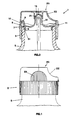
- Figure 1 shows a view of the cap according to the invention;
- Figure 2 shows a section of the cap when closed;
- Figure 3 shows a section of the cap with open cover;
- Figure 4 shows a top view of the cap.
- With reference to the above-mentioned figures it can be noticed that the cap, referred to as a whole by 1, has a main body, referred to as a whole by 2, which has a first substantially cylindrical
outer wall 3 and is provided inside with a thread 4 allowing the cap to be screwed onto theneck 5 of the deformable container. The diameter of a second wall, referred to by 6, which is cylindrical, too, and is substantially coaxial with respect to the firstouter wall 3, is such as to make it possible to introduce its outer wall into the inner edge of theneck 5, so as to obtain the seal between the main body of the cap and theneck 5 of the container. Another seal is accomplished by a circular projection-shaped ring, referred to by 7; this ring-projection 7 gets in contrast with the planeupper part 51 of the neck of thecontainer 5, as shown in Figure 1. Together With thecylindrical wall 6, this ring-projection 7 contributes to the achievement of the seal between the cap and the neck of the container. It will be noticed later on that this particular double-seal structure ensures that there will be no outflow of liquid, which could have occurred because of the hole on the base surface of the main body. - As a matter of fact, as figure 4 shows more clearly, the base surface of the
main body 2 has anopening 8 suitable for the passage of the male through themain body 2 when the thermoplastic moulding of thehook 9 takes place. Thishook 9 cooperates with thecorresponding projection 10 of the wall of thecover 20 when the cover closes on the main body of the cap. - In the
main body 2, in central position, there is also a generallycylindrical part 12 that projects upwards and has ahole 13 arranged in non-axial position, so that the liquid sprayed through said hole is directed forward with respect to the opening of the container. - Inside, the
cylindrical part 12 has somefins 14 serving to fasten asuction pipe 15 that draws the liquid from the bottom of the container. The liquid is drawn out owing to the compression that is obtained by deforming the container itself. The cover, which is connected by means of ahinge 11 made of thermoplastic material, too, and is carried out by moulding together with the main body, has a hollowcylindrical element 21 in the middle, which will house thecylindrical part 12 of the main body when the cover closes on the main body itself. - Further, it can be noticed that the
upper back wall 22 of thecover 20 is concave and its concave part faces outwards. - More precisely, said
wall 22 is part of a cylindrical surface of a cylinder, the horizontal axis of which is perpendicular to the cap axis. This device allows thecover 20 to deform stretching out forwards and to separate from thehook 9 when compression is exerted on the middle of the cover with the fingers of one hand opposite to each other, especially in the twoknurled sections 23, only one of which is shown in Figure 1. - With reference to figure 3, it is clear that the cap object of the invention can be carried out by moulding it with thermoplastic material by means of a single mould provided with only one male part and one female part, since the
hook 9 can be carried out with a projection of the male reaching the lower part of the horizontal wall of said hook, without making undercuts owing to the presence of thehole 8. - The simplification of the mould obviously results also in a reduction of the cost of the cap itself.
- It has been observed that this simplification in itself does absolutely not compromise the sealing characteristics of said cap, since the second
cylindrical wall 6 and the ring-projection 7, along with the thread 4, ensure the seal.
Claims (3)
- A moulded plastic cap for dispensing liquids to be connected to the neck of a deformable container and comprising :characterized in that said main body (2) presents a hole (8) in the base surface in correspondence with where the hook (9) is fixed and under said hook, through which hole (8) a part of the mould male moving in the direction of the axis of said main body can pass during the moulding of the cap with thermoplastic material, anda main body (2) having a first substantially cylindrical outer wall (3) to be connected to the neck (5) of the container and coaxial with respect to a second cylindrical wall (5) to be introduced inside the neck of the container, said main body being provided in the middle with a generally hollow cylindrical part (12), projecting upwards the walls (3,6) thereof being provided with fins (14) for fastening a suction pipe (15) far drawing the liquid out of the container, and having a non-axial outlet (13) for the liquid, said main body being provided in the front part of the cap with a hook (9) placed approximately near the perimetrical edge of said body and projecting from the base surface of said main body, suitable for cooperating with a corresponding projection of a cover;a cover (20) connected with said main body (2) by means of an elastic hinge (11), said cover having a hollow cylindrical element (21) housing the cylindrical part (12) of said main body, when said cover is closed, and having, in its inside edge, a hook-shaped projection (10) cooperating with the corresponding hook (9) of the main body,
that the main body has a ring-projection (7) between the first outer wall (3) and the second cylindrical wall (6), said projection (7) matching the upper surface (51) of the edge of the container and radially inside of said hole (8) in order to seal the cap against the edge of the container. - Cap according to claim 1), characterized in that the main body (2) and the cover (20) are carried out in a single piece by means of moulding of thermoplastic material.
- Cap according to each one of the preceding claims, characterized in that the upper surface (22) of the cover (20) proximate to the hinge is concave and its concave part faces outwards, said surface being part of a cylindrical surface of a cylinder, the main axis of which is perpendicular to the cap axis.
Applications Claiming Priority (3)
| Application Number | Priority Date | Filing Date | Title |
|---|---|---|---|
| ITVI930071 | 1993-05-06 | ||
| IT93VI000071A IT1275356B1 (en) | 1993-05-06 | 1993-05-06 | PLASTIC PLUG FOR THE DISTRIBUTION OF LIQUIDS |
| PCT/EP1994/001427 WO1994026611A1 (en) | 1993-05-06 | 1994-05-05 | Plastic cap for dispensing liquids |
Publications (3)
| Publication Number | Publication Date |
|---|---|
| EP0649380A1 EP0649380A1 (en) | 1995-04-26 |
| EP0649380B1 EP0649380B1 (en) | 1997-03-12 |
| EP0649380B2 true EP0649380B2 (en) | 2000-01-26 |
Family
ID=11425208
Family Applications (1)
| Application Number | Title | Priority Date | Filing Date |
|---|---|---|---|
| EP94916936A Expired - Lifetime EP0649380B2 (en) | 1993-05-06 | 1994-05-05 | Plastic cap for dispensing liquids |
Country Status (8)
| Country | Link |
|---|---|
| US (1) | US5683016A (en) |
| EP (1) | EP0649380B2 (en) |
| AT (1) | ATE149947T1 (en) |
| CA (1) | CA2138169A1 (en) |
| DE (1) | DE69402026T3 (en) |
| ES (1) | ES2098952T5 (en) |
| IT (1) | IT1275356B1 (en) |
| WO (1) | WO1994026611A1 (en) |
Families Citing this family (20)
| Publication number | Priority date | Publication date | Assignee | Title |
|---|---|---|---|---|
| NL1006636C2 (en) * | 1997-07-21 | 1999-01-25 | Itsac Nv | Connection assembly for a fluid connection. |
| AU2002301377B2 (en) * | 1997-07-21 | 2004-08-26 | Itsac N.V. | Connector assembly for a fluid connection |
| EP1147054B1 (en) * | 1999-01-27 | 2002-12-11 | Creanova AG | Closure extruded in closed state |
| IL131067A (en) * | 1999-07-23 | 2002-07-25 | Menachem Vine | Hinged cover for a disposable cup dispenser |
| US6343725B1 (en) | 2000-12-19 | 2002-02-05 | Owens-Illinois Closure Inc. | Disk-type toggle-action dispensing closure, package and method of assembly |
| CA2491283A1 (en) * | 2002-07-03 | 2004-01-15 | Crown Packaging Technology Inc. | Water-soluble container |
| US6772902B1 (en) * | 2003-06-20 | 2004-08-10 | Colin White | One-piece molded child-proof container |
| MY137973A (en) * | 2003-10-31 | 2009-04-30 | Obrist Closures Switzerland | A tamper-evident closure |
| MXPA06014641A (en) * | 2004-06-30 | 2008-03-11 | Obrist Closures Switzerland | Dispensing closure. |
| BRPI0611178A2 (en) * | 2005-04-29 | 2010-08-17 | Obrist Closures Switzerland | tamper evident tamper proof closure |
| GB0608433D0 (en) * | 2006-04-28 | 2006-06-07 | Obrist Closures Switzerland | Closure with RFID device |
| GB2450939B (en) | 2007-07-13 | 2012-02-01 | Obrist Closures Switzerland | Tamper-Evident closure |
| GB2450940B (en) * | 2007-07-13 | 2011-11-30 | Obrist Closures Switzerland | Tamper-evident closure |
| GB0721330D0 (en) * | 2007-10-31 | 2007-12-12 | Obrist Closures Switzerland | Tamper Evident closure |
| US20100320168A1 (en) * | 2008-02-19 | 2010-12-23 | Martin Carey Bull | Child-resistant closure |
| GB0806190D0 (en) * | 2008-04-04 | 2008-05-14 | Obrist Closures Switzerland | A closure |
| GB0816643D0 (en) * | 2008-09-11 | 2008-10-22 | Obrist Closures Switzerland | A closure |
| USD630093S1 (en) | 2010-06-11 | 2011-01-04 | Obrist Closures Switzerland Gmbh | Closure |
| DE102017209085B4 (en) * | 2017-05-30 | 2022-02-17 | Henkel Ag & Co. Kgaa | Closure with hinged lid |
| US11059633B2 (en) | 2019-10-31 | 2021-07-13 | Cheer Pack North America | Flip-top closure for container |
Citations (8)
| Publication number | Priority date | Publication date | Assignee | Title |
|---|---|---|---|---|
| ES192908A1 (en) † | 1950-05-09 | 1951-05-16 | Saunders Valve Co Ltd | IMPROVEMENTS MADE IN TAPS OR MALE VALVES |
| US3651992A (en) † | 1970-03-23 | 1972-03-28 | Polytop Corp | Tamper-proof closure |
| DE2435337A1 (en) † | 1974-07-23 | 1976-02-05 | Nova Handels Ag | CHILD-PROOF LOCK |
| DE2805046A1 (en) † | 1977-02-10 | 1978-08-17 | Createchnic Patent Ag | PLASTIC LATCH FOR FIXED AND DEFORMABLE CONTAINERS |
| DE2828065A1 (en) † | 1978-06-27 | 1980-01-10 | Wischerath Kg Josef | PLASTIC LID LOCK FOR CONTAINERS, ESPECIALLY FOR PACKAGING PURPOSES |
| EP0210138A2 (en) † | 1985-07-23 | 1987-01-28 | Alfatechnic Ag | Plastic closure with a tamper-proof strip |
| DE3632057A1 (en) † | 1985-12-14 | 1987-06-25 | Vedder & Comp Gmbh | CLOSURE |
| FR2633590A1 (en) † | 1988-07-01 | 1990-01-05 | Astra Plastique | Spout-stopper made of synthetic material with an articulated cap |
Family Cites Families (9)
| Publication number | Priority date | Publication date | Assignee | Title |
|---|---|---|---|---|
| US2571504A (en) * | 1949-09-16 | 1951-10-16 | Pharma Craft Corp | Thermoplastic spray bottle |
| US3381860A (en) * | 1966-12-30 | 1968-05-07 | Monsanto Co | Variable intensity spray dispenser |
| US3710989A (en) * | 1969-11-06 | 1973-01-16 | Monsanto Co | Spray dispensing cap and hinged closure |
| DE2155664A1 (en) * | 1970-11-13 | 1972-06-29 | Captocap Ltd., Vaduz | Closure |
| GB2076378B (en) * | 1980-05-09 | 1984-02-15 | Windmill Plastics Ltd | Closure for container |
| GB8625169D0 (en) * | 1986-10-21 | 1986-11-26 | Duma Packaging As | Closure assembly |
| US4809874A (en) * | 1988-02-26 | 1989-03-07 | Pehr Harold T | Hinged closure for containers |
| US4838441A (en) * | 1988-04-11 | 1989-06-13 | Chernack Milton P | Child resistant closure |
| US4940167A (en) * | 1989-01-27 | 1990-07-10 | Owens-Illinois Closure Inc. | Child resistant dispensing closure |
-
1993
- 1993-05-06 IT IT93VI000071A patent/IT1275356B1/en active IP Right Grant
-
1994
- 1994-05-05 AT AT94916936T patent/ATE149947T1/en not_active IP Right Cessation
- 1994-05-05 DE DE69402026T patent/DE69402026T3/en not_active Expired - Fee Related
- 1994-05-05 ES ES94916936T patent/ES2098952T5/en not_active Expired - Lifetime
- 1994-05-05 US US08/362,428 patent/US5683016A/en not_active Expired - Lifetime
- 1994-05-05 EP EP94916936A patent/EP0649380B2/en not_active Expired - Lifetime
- 1994-05-05 WO PCT/EP1994/001427 patent/WO1994026611A1/en active IP Right Grant
- 1994-05-05 CA CA002138169A patent/CA2138169A1/en not_active Abandoned
Patent Citations (9)
| Publication number | Priority date | Publication date | Assignee | Title |
|---|---|---|---|---|
| ES192908A1 (en) † | 1950-05-09 | 1951-05-16 | Saunders Valve Co Ltd | IMPROVEMENTS MADE IN TAPS OR MALE VALVES |
| US3651992A (en) † | 1970-03-23 | 1972-03-28 | Polytop Corp | Tamper-proof closure |
| DE2435337A1 (en) † | 1974-07-23 | 1976-02-05 | Nova Handels Ag | CHILD-PROOF LOCK |
| ES212300U (en) † | 1974-07-23 | 1976-06-01 | Nova-Handels Ag | A closure, especially for bottles of bottles or containers. (Machine-translation by Google Translate, not legally binding) |
| DE2805046A1 (en) † | 1977-02-10 | 1978-08-17 | Createchnic Patent Ag | PLASTIC LATCH FOR FIXED AND DEFORMABLE CONTAINERS |
| DE2828065A1 (en) † | 1978-06-27 | 1980-01-10 | Wischerath Kg Josef | PLASTIC LID LOCK FOR CONTAINERS, ESPECIALLY FOR PACKAGING PURPOSES |
| EP0210138A2 (en) † | 1985-07-23 | 1987-01-28 | Alfatechnic Ag | Plastic closure with a tamper-proof strip |
| DE3632057A1 (en) † | 1985-12-14 | 1987-06-25 | Vedder & Comp Gmbh | CLOSURE |
| FR2633590A1 (en) † | 1988-07-01 | 1990-01-05 | Astra Plastique | Spout-stopper made of synthetic material with an articulated cap |
Also Published As
| Publication number | Publication date |
|---|---|
| DE69402026T3 (en) | 2000-10-26 |
| DE69402026D1 (en) | 1997-04-17 |
| ES2098952T3 (en) | 1997-05-01 |
| IT1275356B1 (en) | 1997-08-05 |
| EP0649380A1 (en) | 1995-04-26 |
| ITVI930071A1 (en) | 1994-11-06 |
| CA2138169A1 (en) | 1994-11-24 |
| ES2098952T5 (en) | 2000-04-16 |
| ITVI930071A0 (en) | 1993-05-06 |
| ATE149947T1 (en) | 1997-03-15 |
| US5683016A (en) | 1997-11-04 |
| WO1994026611A1 (en) | 1994-11-24 |
| EP0649380B1 (en) | 1997-03-12 |
| DE69402026T2 (en) | 1997-10-09 |
Similar Documents
| Publication | Publication Date | Title |
|---|---|---|
| EP0649380B2 (en) | Plastic cap for dispensing liquids | |
| US6257431B1 (en) | Dispensing cap with improved tightness | |
| JP3725190B2 (en) | Dispensing assembly with attached unidirectional closure | |
| US2690861A (en) | Dispensing closure | |
| US4550862A (en) | Liquid product pouring and measuring package with self draining feature | |
| US6116477A (en) | Two piece hinge closure | |
| US5655687A (en) | Base end dispensing container with travel cap | |
| US4903870A (en) | Dispensing closure | |
| US9156569B2 (en) | Pediatric dosing dispenser | |
| US5819984A (en) | Package with storage and plug retention features | |
| GB2150102A (en) | Liquid container with combined measuring and closure cap | |
| GB2430667A (en) | A tamper evident closure | |
| US10639236B2 (en) | Pediatric dosing dispenser | |
| CN101146719A (en) | Dispensing closure, package and method of manufacture | |
| MXPA04002673A (en) | Dispensing closure for a container that holds pourable material. | |
| JP2964167B2 (en) | Automatic closed dispenser for containers containing liquid or pasty products | |
| US6439433B1 (en) | Pouring device | |
| RU2404906C2 (en) | Distribution caps for liquid containers | |
| US4961515A (en) | Closure for a bottle | |
| US7703634B2 (en) | Air valve for a cap provided with mouthpiece for drinking | |
| WO1996001216A2 (en) | Pour spout assembly for bottles | |
| EP1339617A1 (en) | Dispensing closure for a container | |
| CA1334083C (en) | Cap for collapsible bottles and the like | |
| US5692652A (en) | Self-closing valve for bottles | |
| JP3010280U (en) | Pill fur proof cap |
Legal Events
| Date | Code | Title | Description |
|---|---|---|---|
| PUAI | Public reference made under article 153(3) epc to a published international application that has entered the european phase |
Free format text: ORIGINAL CODE: 0009012 |
|
| 17P | Request for examination filed |
Effective date: 19950203 |
|
| AK | Designated contracting states |
Kind code of ref document: A1 Designated state(s): AT BE CH DE DK ES FR GB GR IT LI NL SE |
|
| GRAG | Despatch of communication of intention to grant |
Free format text: ORIGINAL CODE: EPIDOS AGRA |
|
| GRAH | Despatch of communication of intention to grant a patent |
Free format text: ORIGINAL CODE: EPIDOS IGRA |
|
| 17Q | First examination report despatched |
Effective date: 19960723 |
|
| RAP1 | Party data changed (applicant data changed or rights of an application transferred) |
Owner name: TAPLAST S.P.A. |
|
| GRAH | Despatch of communication of intention to grant a patent |
Free format text: ORIGINAL CODE: EPIDOS IGRA |
|
| GRAA | (expected) grant |
Free format text: ORIGINAL CODE: 0009210 |
|
| AK | Designated contracting states |
Kind code of ref document: B1 Designated state(s): AT BE CH DE DK ES FR GB GR IT LI NL SE |
|
| PG25 | Lapsed in a contracting state [announced via postgrant information from national office to epo] |
Ref country code: NL Free format text: LAPSE BECAUSE OF FAILURE TO SUBMIT A TRANSLATION OF THE DESCRIPTION OR TO PAY THE FEE WITHIN THE PRESCRIBED TIME-LIMIT Effective date: 19970312 Ref country code: LI Effective date: 19970312 Ref country code: GR Free format text: LAPSE BECAUSE OF FAILURE TO SUBMIT A TRANSLATION OF THE DESCRIPTION OR TO PAY THE FEE WITHIN THE PRESCRIBED TIME-LIMIT Effective date: 19970312 Ref country code: DK Effective date: 19970312 Ref country code: CH Effective date: 19970312 Ref country code: AT Effective date: 19970312 |
|
| REF | Corresponds to: |
Ref document number: 149947 Country of ref document: AT Date of ref document: 19970315 Kind code of ref document: T |
|
| REG | Reference to a national code |
Ref country code: CH Ref legal event code: EP |
|
| REF | Corresponds to: |
Ref document number: 69402026 Country of ref document: DE Date of ref document: 19970417 |
|
| REG | Reference to a national code |
Ref country code: ES Ref legal event code: FG2A Ref document number: 2098952 Country of ref document: ES Kind code of ref document: T3 |
|
| PGFP | Annual fee paid to national office [announced via postgrant information from national office to epo] |
Ref country code: BE Payment date: 19970529 Year of fee payment: 4 |
|
| ET | Fr: translation filed | ||
| ITF | It: translation for a ep patent filed |
Owner name: STUDIO ING. E. BONINI S.R.L. |
|
| PG25 | Lapsed in a contracting state [announced via postgrant information from national office to epo] |
Ref country code: SE Effective date: 19970612 |
|
| NLV1 | Nl: lapsed or annulled due to failure to fulfill the requirements of art. 29p and 29m of the patents act | ||
| REG | Reference to a national code |
Ref country code: CH Ref legal event code: PL |
|
| PLBQ | Unpublished change to opponent data |
Free format text: ORIGINAL CODE: EPIDOS OPPO |
|
| PLBI | Opposition filed |
Free format text: ORIGINAL CODE: 0009260 |
|
| PLBF | Reply of patent proprietor to notice(s) of opposition |
Free format text: ORIGINAL CODE: EPIDOS OBSO |
|
| 26 | Opposition filed |
Opponent name: ZELLER PLASTIK GMBH Effective date: 19971211 |
|
| PG25 | Lapsed in a contracting state [announced via postgrant information from national office to epo] |
Ref country code: BE Free format text: LAPSE BECAUSE OF NON-PAYMENT OF DUE FEES Effective date: 19980531 |
|
| PLBF | Reply of patent proprietor to notice(s) of opposition |
Free format text: ORIGINAL CODE: EPIDOS OBSO |
|
| PLBF | Reply of patent proprietor to notice(s) of opposition |
Free format text: ORIGINAL CODE: EPIDOS OBSO |
|
| PLBF | Reply of patent proprietor to notice(s) of opposition |
Free format text: ORIGINAL CODE: EPIDOS OBSO |
|
| BERE | Be: lapsed |
Owner name: TAPLAST S.P.A. Effective date: 19980531 |
|
| PLBQ | Unpublished change to opponent data |
Free format text: ORIGINAL CODE: EPIDOS OPPO |
|
| PLBI | Opposition filed |
Free format text: ORIGINAL CODE: 0009260 |
|
| 26 | Opposition filed |
Opponent name: EMBALAPLAS S.A. Effective date: 19981221 Opponent name: ZELLER PLASTIK GMBH Effective date: 19971211 |
|
| PLAW | Interlocutory decision in opposition |
Free format text: ORIGINAL CODE: EPIDOS IDOP |
|
| PLAW | Interlocutory decision in opposition |
Free format text: ORIGINAL CODE: EPIDOS IDOP |
|
| PUAH | Patent maintained in amended form |
Free format text: ORIGINAL CODE: 0009272 |
|
| STAA | Information on the status of an ep patent application or granted ep patent |
Free format text: STATUS: PATENT MAINTAINED AS AMENDED |
|
| 27A | Patent maintained in amended form |
Effective date: 20000126 |
|
| AK | Designated contracting states |
Kind code of ref document: B2 Designated state(s): AT BE CH DE DK ES FR GB GR IT LI NL SE |
|
| REG | Reference to a national code |
Ref country code: ES Ref legal event code: DC2A Kind code of ref document: T5 Effective date: 20000308 |
|
| ITF | It: translation for a ep patent filed |
Owner name: STUDIO ING. E. BONINI S.R.L. |
|
| ET3 | Fr: translation filed ** decision concerning opposition | ||
| ET2 | Fr: translation filed ** revision of the translation of the modified patent after opposition | ||
| ET3 | Fr: translation filed ** decision concerning opposition | ||
| REG | Reference to a national code |
Ref country code: GB Ref legal event code: IF02 |
|
| PGFP | Annual fee paid to national office [announced via postgrant information from national office to epo] |
Ref country code: DE Payment date: 20050428 Year of fee payment: 12 |
|
| PGFP | Annual fee paid to national office [announced via postgrant information from national office to epo] |
Ref country code: GB Payment date: 20050504 Year of fee payment: 12 |
|
| PGFP | Annual fee paid to national office [announced via postgrant information from national office to epo] |
Ref country code: FR Payment date: 20050511 Year of fee payment: 12 |
|
| PGFP | Annual fee paid to national office [announced via postgrant information from national office to epo] |
Ref country code: ES Payment date: 20050624 Year of fee payment: 12 |
|
| PG25 | Lapsed in a contracting state [announced via postgrant information from national office to epo] |
Ref country code: GB Free format text: LAPSE BECAUSE OF NON-PAYMENT OF DUE FEES Effective date: 20060505 |
|
| PG25 | Lapsed in a contracting state [announced via postgrant information from national office to epo] |
Ref country code: ES Free format text: LAPSE BECAUSE OF NON-PAYMENT OF DUE FEES Effective date: 20060506 |
|
| PGFP | Annual fee paid to national office [announced via postgrant information from national office to epo] |
Ref country code: IT Payment date: 20060531 Year of fee payment: 13 |
|
| PG25 | Lapsed in a contracting state [announced via postgrant information from national office to epo] |
Ref country code: DE Free format text: LAPSE BECAUSE OF NON-PAYMENT OF DUE FEES Effective date: 20061201 |
|
| GBPC | Gb: european patent ceased through non-payment of renewal fee |
Effective date: 20060505 |
|
| REG | Reference to a national code |
Ref country code: FR Ref legal event code: ST Effective date: 20070131 |
|
| REG | Reference to a national code |
Ref country code: ES Ref legal event code: FD2A Effective date: 20060506 |
|
| PG25 | Lapsed in a contracting state [announced via postgrant information from national office to epo] |
Ref country code: FR Free format text: LAPSE BECAUSE OF NON-PAYMENT OF DUE FEES Effective date: 20060531 |
|
| PLAB | Opposition data, opponent's data or that of the opponent's representative modified |
Free format text: ORIGINAL CODE: 0009299OPPO |
|
| PG25 | Lapsed in a contracting state [announced via postgrant information from national office to epo] |
Ref country code: IT Free format text: LAPSE BECAUSE OF NON-PAYMENT OF DUE FEES Effective date: 20070505 |