EP0649363B1 - Stapler - Google Patents
Stapler Download PDFInfo
- Publication number
- EP0649363B1 EP0649363B1 EP93912935A EP93912935A EP0649363B1 EP 0649363 B1 EP0649363 B1 EP 0649363B1 EP 93912935 A EP93912935 A EP 93912935A EP 93912935 A EP93912935 A EP 93912935A EP 0649363 B1 EP0649363 B1 EP 0649363B1
- Authority
- EP
- European Patent Office
- Prior art keywords
- staple
- pusher
- limbs
- magazine
- stapler according
- Prior art date
- Legal status (The legal status is an assumption and is not a legal conclusion. Google has not performed a legal analysis and makes no representation as to the accuracy of the status listed.)
- Expired - Lifetime
Links
- 239000000463 material Substances 0.000 claims abstract description 10
- 239000002184 metal Substances 0.000 claims abstract description 6
- 230000000284 resting effect Effects 0.000 claims 1
- 210000002414 leg Anatomy 0.000 description 28
- 238000004049 embossing Methods 0.000 description 5
- 210000003128 head Anatomy 0.000 description 4
- 230000007257 malfunction Effects 0.000 description 2
- 210000000689 upper leg Anatomy 0.000 description 2
- 230000001419 dependent effect Effects 0.000 description 1
- 238000011161 development Methods 0.000 description 1
- 230000018109 developmental process Effects 0.000 description 1
- 210000001061 forehead Anatomy 0.000 description 1
- 238000004519 manufacturing process Methods 0.000 description 1
- 238000000034 method Methods 0.000 description 1
- 238000003825 pressing Methods 0.000 description 1
Images
Classifications
-
- B—PERFORMING OPERATIONS; TRANSPORTING
- B25—HAND TOOLS; PORTABLE POWER-DRIVEN TOOLS; MANIPULATORS
- B25C—HAND-HELD NAILING OR STAPLING TOOLS; MANUALLY OPERATED PORTABLE STAPLING TOOLS
- B25C5/00—Manually operated portable stapling tools; Hand-held power-operated stapling tools; Staple feeding devices therefor
- B25C5/02—Manually operated portable stapling tools; Hand-held power-operated stapling tools; Staple feeding devices therefor with provision for bending the ends of the staples on to the work
- B25C5/0221—Stapling tools of the table model type, i.e. tools supported by a table or the work during operation
- B25C5/0242—Stapling tools of the table model type, i.e. tools supported by a table or the work during operation having a pivoting upper leg and a leg provided with an anvil supported by the table or work
- B25C5/025—Stapling tools of the table model type, i.e. tools supported by a table or the work during operation having a pivoting upper leg and a leg provided with an anvil supported by the table or work the plunger being manually operated
-
- B—PERFORMING OPERATIONS; TRANSPORTING
- B25—HAND TOOLS; PORTABLE POWER-DRIVEN TOOLS; MANIPULATORS
- B25C—HAND-HELD NAILING OR STAPLING TOOLS; MANUALLY OPERATED PORTABLE STAPLING TOOLS
- B25C5/00—Manually operated portable stapling tools; Hand-held power-operated stapling tools; Staple feeding devices therefor
- B25C5/16—Staple-feeding devices, e.g. with feeding means, supports for staples or accessories concerning feeding devices
- B25C5/1606—Feeding means
- B25C5/1617—Feeding means employing a spring-loaded pusher
Definitions
- the invention relates to a stapling device with a staple magazine that can be pivoted to a limited extent on a base part for receiving staples lined up in packs one behind the other, with their side legs guided between side walls of the staple magazine, and with a forehead guide that is guided in a slide guide of the staple magazine, preferably designed as a bent sheet metal part mutually parallel, against the side walls of the staple magazine slide leg against the side legs of the staple package located in the staple magazine under the action of a spring and by means of a pulling mechanism that can be lifted against the force of the spring by the clamp slide.
- Such a stapling device designed as an upper loader is known from GB-A-2 128 127.
- the staples in the staple magazine are pushed towards the magazine head with the aid of the clamp slide under the action of the spring, so that a staple is always available in the magazine head for ejection by a driver.
- the upper part of the stapler is folded around the transverse axis into a loading position that is opened by 180 ° and the staple slide is carried in the slide guide of the staple magazine against the spring force.
- the slider is retracted either via a tension spring or a pull tab.
- a tension spring or a pull tab points the staple slide on stop tabs that protrude upwards over the top edge of the staples inserted in the magazine. It is thereby achieved that the pull tab guided in a lateral guide of the magazine walls above the staples can grip the staple slide when the upper part is opened and can lift off the staples.
- a magazine cover is provided, which serves as a hold-down for the staples in the staple magazine. In order to be able to apply the hold-down of the staples to the outside of the bend of the clip web, it is desirable that the slide and its stop tabs projecting upward are made relatively thin-walled.
- the staple pusher of the generic staple device has an essentially inverted U-shaped cross section with an upper wall and two opposing smooth pusher legs. Since the staple pusher has the task of pressing the staples lined up one behind the other on their legs in the direction of the magazine head, there is a risk that the staple pusher is thin-walled and there is a risk of wedging between the pusher legs and the staples in the rear region of the staple package. In this case, stapling malfunctions may occur, causing the stapler to malfunction.
- Also known is an embodiment of a magazine of a driving tool for receiving fasteners, in which a slide is provided, the one, longer slide leg of which has a crank.
- the known magazine is designed so that it can process both staples and nails.
- the slide (together with the inner support) is arranged so that it can be moved transversely in the guide channel of the magazine in such a way that in one functional position (clamp transport) it bends into a side groove and its other functional position (nail transport) in the other functional position (clamp transport) engages with its shorter slide arm in a guide recess in the magazine wall.
- staple transport which is of the essence according to the invention
- the cranking has only a guiding function.
- this document does not provide any suggestion for the transverse deformation of both slide legs in the direction of the inside of the leg.
- the object of the invention is to develop a staple device of the type mentioned at the outset, in which reliable staple transport is ensured even with a thin-walled staple slide and taking into account the dimensional tolerances that occur during the manufacture of staples.
- the solution according to the invention is based on the idea that the effective transverse dimensions of the end edges of the slide striking against the clamp legs, which are decisive for a reliable slide stop, can be enlarged by a transverse deformation in the case of thin-walled material.
- the legs of the clamp slide have a transverse deformation at least in the area of their front edges.
- the transverse deformation can be designed as an embossing which points towards the inside of the slide legs and thus towards the inside of the magazine.
- the embossing expediently has a depth corresponding to 0.5 to 2 times the material thickness, so that the transverse dimension of the end edges which is significantly effective for the leg stop corresponds to 1.5 to 3 times the material thickness.
- a preferred embodiment of the invention provides that the transverse deformation in the region of the front edge has the shape of a bulge or crank that extends over 1/3 to 2/3 of the leg length.
- the clamp slide has a substantially U-shaped profile which is delimited by the legs and a web connecting the legs to one another, the legs having a frontal projection delimited by the front edges, the height of which suitably corresponds to 1 to 5 times the material thickness .
- the embossing advantageously extends over the entire height of the projection. This gives the embossing an additional stiffening function. In principle, it is possible to extend the embossing over a larger part of the slide length or over the entire slide length.
- a stop tab projecting in the thigh plane at a distance from the front edge over the top edge of the thighs is advantageously provided, which has a stop facing the end face for the pulling element designed as a pull tab.
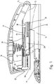
- the staple device shown in the drawing essentially consists of an elongated base part 14, which has an anvil plate 10 in its front area and a bearing block 12 in its rear area, a bracket magazine 22 which can be pivoted to a limited extent against a spring 16 on the bearing block 12 about a transverse axis 16 , a slide slide 28 guided in a slide guide 24 of the clip magazine 22 and supported in the direction of the magazine head 20 by a spring 26 and a clip slide 28 about the transverse axis 16 with respect to the clip slide 28 and the bottom part 14 by about 180 ° from a closed position into an opened loading position while taking the Clamp slide pivotable, a magazine cover 31 supported by a spring 30 and an upper part 34 carrying a driver 32 engaging in the magazine part 20 of the clip magazine.
- the pull tab 36 is supported at one end by a hinge 38 on the magazine cover 31 and with its a the other end in a slide guide 40 of the clip magazine 22.
- the pull tab 36 abuts the clamp slide 28 and takes it against the force of the spring 26 into its end position which is lifted off the staples 41.
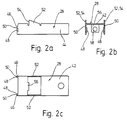
- the clamp slide 28 is designed as a bent sheet metal part which is essentially U-shaped in cross section, consisting of a web 42 and two perpendicular to the web bent legs 44.
- the legs 44 On their front side abutting against the clamp legs, the legs 44 have a projection 46, the height of which corresponds approximately to 1.5 times the material thickness.
- the legs 44 In the area of the protrusion 46, the legs 44 have embossments 48 oriented toward the inside of the leg, which have a crank-like course along the end edge 50 and, compared to the material thickness, roughly double the effective cross-sectional dimensions.
- the legs 44 At a distance from the front edge 50, the legs 44 have stop tabs 52 projecting upward with a stop edge 54 directed toward the front edge 50 for the stop of the pull tab 36. Furthermore, a downwardly bent guide plate 56 is formed in the region of the slide web 42 with a round hole 58, with which the clamp slide 28 is guided on a round rod of the clamp magazine 22 forming the slide guide 24.
- the invention relates to a staple device with a staple magazine 22 for receiving stacks in a row, with their side legs guided between side walls of the staple magazine 22 and with a staple guide 40 in the drawer guide 40 of the staple magazine 22, designed as a bent sheet metal part. with the front edges 50 of two mutually parallel legs 44 against the side legs of the staple package 41 located in the staple magazine under the action of a spring 26, staple slide 28.
- the legs 44 of the staple pusher 28 have an offset-like transverse deformation 48 at least in the region of their front edges 50.
Landscapes
- Engineering & Computer Science (AREA)
- Mechanical Engineering (AREA)
- Portable Nailing Machines And Staplers (AREA)
- Valve-Gear Or Valve Arrangements (AREA)
- Materials For Medical Uses (AREA)
- Sewing Machines And Sewing (AREA)
Abstract
Description
Die Erfindung betrifft ein Heftklammergerät mit einem an einem Bodenteil begrenzt verschwenkbaren Klammermagazin zur Aufnahme von paketweise hintereinander aufgereihten, mit ihren Seitenschenkeln zwischen Seitenwänden des Klammermagazins geführten Heftklammern, und mit einem in einer Schubführung des Klammermagazins geführten, vorzugsweise als gebogenes Blechteil ausgebildeten, mit den Stirnkanten zweier zueinander paralleler, gegen die Seitenwände des Klammermagazins anliegender Schieberschenkel gegen die Seitenschenkel des im Klammermagazin befindlichen Heftklammerpakets unter der Einwirkung einer Feder anschlagbaren und mittels eines Zugmechanismus von diesem entgegen der Kraft der Feder abhebbaren Klammerschieber.The invention relates to a stapling device with a staple magazine that can be pivoted to a limited extent on a base part for receiving staples lined up in packs one behind the other, with their side legs guided between side walls of the staple magazine, and with a forehead guide that is guided in a slide guide of the staple magazine, preferably designed as a bent sheet metal part mutually parallel, against the side walls of the staple magazine slide leg against the side legs of the staple package located in the staple magazine under the action of a spring and by means of a pulling mechanism that can be lifted against the force of the spring by the clamp slide.
Ein derartiges als Oberlader ausgebildetes Heftklammergerät ist aus der GB-A-2 128 127 bekannt.Such a stapling device designed as an upper loader is known from GB-A-2 128 127.
Bei als Oberlader ausgebildeten Heftklammergeräten werden die im Klammermagazin befindlichen Heftklammern mit Hilfe des Klammerschiebers unter der Einwirkung der Feder in Richtung Magazinkopf geschoben, so daß im Magazinkopf immer eine Heftklammer zum Ausstoßen durch einen Treiber bereitsteht. Zum Nachfüllen wird das Oberteil des Heftklammergeräts um die Querachse in eine um 180° aufgeklappte Ladestellung geklappt und dabei der Klammerschieber entgegen der Federkraft in der Schubführung des Klammermagazins mitgenommen.In staplers designed as an upper loader, the staples in the staple magazine are pushed towards the magazine head with the aid of the clamp slide under the action of the spring, so that a staple is always available in the magazine head for ejection by a driver. For refilling, the upper part of the stapler is folded around the transverse axis into a loading position that is opened by 180 ° and the staple slide is carried in the slide guide of the staple magazine against the spring force.
Der Schieberrückzug erfolgt dabei entweder über eine Zugfeder oder eine Zuglasche. Im letzteren Falle weist der Klammerschieber Anschlaglappen auf, die nach oben über die Oberkante der in das Magazin eingelegten Heftklammern überstehen. Dadurch wird erreicht, daß die in einer seitlichen Führung der Magazinwände geführte Zuglasche oberhalb der Heftklammern beim Öffnen des Oberteils den Klammerschieber erfassen und von den Heftklammern abheben kann. Andererseits ist eine Magazinabdeckung vorgesehen, die als Niederhalter für die Heftklammern im Klammermagazin dient. Um die Niederhaltung der Heftklammern möglichst außen an der Abbiegung des Klammerstegs ansetzen zu können, ist es erwünscht, daß der Schieber und seine nach oben überstehenden Anschlaglappen relativ dünnwandig ausgeführt sind. Der Klammerschieber des gattungsgemäßen Heftklammergeräts weist einen im wesentlichen umgekehrt U-förmigen Querschnitt mit einer Oberwand und zwei einander gegenüberliegenden glatten Schieberschenkeln auf. Da der Klammerschieber die Aufgabe hat, die hintereinander aufgereihten Heftklammern an ihren Schenkeln in Richtung Magazinkopf zu drücken, besteht bei dünnwandiger Ausbildung des Klammerschiebers die Gefahr, daß es im rückwärtigen Bereich des Klammerpakets zu einem Verkeilen zwischen den Schieberschenkeln und den Klammern kommt. In diesem Fall kann es zu Störungen im Klammertransport und damit zu einer Fehlfunktion des Heftgeräts kommen.The slider is retracted either via a tension spring or a pull tab. In the latter case points the staple slide on stop tabs that protrude upwards over the top edge of the staples inserted in the magazine. It is thereby achieved that the pull tab guided in a lateral guide of the magazine walls above the staples can grip the staple slide when the upper part is opened and can lift off the staples. On the other hand, a magazine cover is provided, which serves as a hold-down for the staples in the staple magazine. In order to be able to apply the hold-down of the staples to the outside of the bend of the clip web, it is desirable that the slide and its stop tabs projecting upward are made relatively thin-walled. The staple pusher of the generic staple device has an essentially inverted U-shaped cross section with an upper wall and two opposing smooth pusher legs. Since the staple pusher has the task of pressing the staples lined up one behind the other on their legs in the direction of the magazine head, there is a risk that the staple pusher is thin-walled and there is a risk of wedging between the pusher legs and the staples in the rear region of the staple package. In this case, stapling malfunctions may occur, causing the stapler to malfunction.
Ebenfalls bekannt (DE-U-8 710 524) ist eine Ausführungsform eines Magazins eines Eintreibgeräts zur Aufnahme von Befestigungsmitteln, bei welchem ein Schieber vorgesehen ist, dessen einer, längerer Schieberschenkel eine Kröpfung aufweist. Im Unterschied zum Anmeldungsgegenstand ist das bekannte Magazin so ausgebildet, daß es sowohl Heftklammern als auch Nägel verarbeiten kann. Zu diesem Zweck ist der Schieber (zusammen mit dem inneren Träger) in dem Führungskanal des Magazins so quer verschiebbar angeordnet, daß es in der einen Funktionsstellung (Klammertransport) mit seiner nach dem Schieberäußeren weisenden Kröpfung in eine Seitennut und in seiner anderen Funktionsstellung (Nageltransport) mit seinem kürzeren Schieberschenkel in eine Führungsaussparung der Magazinwand eingreift. Beim Klammertransport, auf den es gemäß der Erfindung gerade ankommt, kommt der Kröpfung ausschließlich eine Führungsfunktion zu. Eine Anregung zur Querverformung beider Schieberschenkel in Richtung Schenkelinneres ist jedoch dieser Schrift nicht entnehmbar.Also known (DE-U-8 710 524) is an embodiment of a magazine of a driving tool for receiving fasteners, in which a slide is provided, the one, longer slide leg of which has a crank. In contrast to the subject of the application, the known magazine is designed so that it can process both staples and nails. For this purpose, the slide (together with the inner support) is arranged so that it can be moved transversely in the guide channel of the magazine in such a way that in one functional position (clamp transport) it bends into a side groove and its other functional position (nail transport) in the other functional position (clamp transport) engages with its shorter slide arm in a guide recess in the magazine wall. In the case of staple transport, which is of the essence according to the invention, the cranking has only a guiding function. However, this document does not provide any suggestion for the transverse deformation of both slide legs in the direction of the inside of the leg.
Ausgehend hiervon liegt der Erfindung die Aufgabe zugrunde, ein Heftklammergerät der eingangs genannten Gattung zu entwickeln, bei welchem auch mit einem dünnwandigen Klammerschieber und unter Berücksichtigung der bei der Herstellung von Heftklammern auftretenden Maßtoleranzen ein zuverlässiger Klammertransport gewährleistet ist.Proceeding from this, the object of the invention is to develop a staple device of the type mentioned at the outset, in which reliable staple transport is ensured even with a thin-walled staple slide and taking into account the dimensional tolerances that occur during the manufacture of staples.
Zur Lösung dieser Aufgabe werden die im Patentanspruch 1 angegebenen Merkmale vorgeschlagen. Vorteilhafte Ausgestaltungen und Weiterbildungen der Erfindung ergeben sich aus den abhängigen Ansprüchen.To solve this problem are in the claim 1 features proposed. Advantageous refinements and developments of the invention result from the dependent claims.
Die erfindungsgemäße Lösung geht von dem Gedanken aus, daß die für einen zuverlässigen Schieberanschlag maßgeblichen effektiven Querabmessungen der gegen die Klammerschenkel anschlagenden Stirnkanten des Schiebers bei dünnwandigem Material durch eine Querverformung vergrößert werden können.The solution according to the invention is based on the idea that the effective transverse dimensions of the end edges of the slide striking against the clamp legs, which are decisive for a reliable slide stop, can be enlarged by a transverse deformation in the case of thin-walled material.
Um dies zu erreichen, wird gemäß der Erfindung vorgeschlagen, daß die Schenkel des Klammerschiebers zumindest im Bereich ihrer Stirnkanten eine Querverformung aufweisen. Bei einem als gebogenes Blechteil ausgebildeten Klammerschieber kann die Querverformung als Prägung ausgebildet werden, die nach dem Inneren der Schieberschenkel und damit nach dem Magazininneren weist. Die Prägung weist dabei zweckmäßig eine dem 0,5- bis 2-fachen der Materialstärke entsprechende Tiefe auf, so daß die für den Schenkelanschlag maßgeblich effektive Querabmessung der Stirnkanten dem 1,5- bis 3-fachen der Materialstärke entspricht.In order to achieve this, it is proposed according to the invention that the legs of the clamp slide have a transverse deformation at least in the area of their front edges. In the case of a clamp slide designed as a bent sheet metal part, the transverse deformation can be designed as an embossing which points towards the inside of the slide legs and thus towards the inside of the magazine. The embossing expediently has a depth corresponding to 0.5 to 2 times the material thickness, so that the transverse dimension of the end edges which is significantly effective for the leg stop corresponds to 1.5 to 3 times the material thickness.
Eine bevorzugte Ausgestaltung der Erfindung sieht vor, daß die Querverformung im Bereich der Stirnkante die Gestalt einer Auswölbung oder Kröpfung aufweist, die sich über 1/3 bis 2/3 der Schenkellänge erstreckt.A preferred embodiment of the invention provides that the transverse deformation in the region of the front edge has the shape of a bulge or crank that extends over 1/3 to 2/3 of the leg length.
Gemäß einer weiteren vorteilhaften Ausgestaltung der Erfindung weist der Klammerschieber ein durch die Schenkel und einen die Schenkel miteinander verbindenden Steg begrenztes, im wesentlichen U-förmiges Profil auf, wobei die Schenkel einen durch die Stirnkanten begrenzten stirnseitigen Vorsprung aufweisen, dessen Höhe zweckmäßig dem 1- bis 5-fachen der Materialstärke entspricht. Die Prägung erstreckt sich vorteilhafterweise über die gesamte Höhe des Vorsprungs. Damit kommt der Prägung eine zusätzliche Aussteifungsfunktion zu. Grundsätzlich ist es möglich, die Prägung auch über einen größeren Teil der Schieberlänge oder über die gesamte Schieberlänge zu erstrecken.According to a further advantageous embodiment of the According to the invention, the clamp slide has a substantially U-shaped profile which is delimited by the legs and a web connecting the legs to one another, the legs having a frontal projection delimited by the front edges, the height of which suitably corresponds to 1 to 5 times the material thickness . The embossing advantageously extends over the entire height of the projection. This gives the embossing an additional stiffening function. In principle, it is possible to extend the embossing over a larger part of the slide length or over the entire slide length.
Für Oberladergeräte mit Laschenrückzug ist vorteilhafterweise je ein in der Schenkelebene im Abstand von der Stirnkante über die Oberkante der Schenkel überstehender Anschlaglappen vorgesehen, der einen zur Stirnseite weisenden Anschlag für das als Zuglasche ausgebildete Zugorgan aufweist.For top-loading devices with tab retraction, a stop tab projecting in the thigh plane at a distance from the front edge over the top edge of the thighs is advantageously provided, which has a stop facing the end face for the pulling element designed as a pull tab.
Im folgenden wird die Erfindung anhand eines in der Zeichnung in schematischer Weise dargestellten Ausführungsbeispiels näher erläutert. Es zeigen
- Fig. 1
- einen Schnitt durch ein als Oberlader mit Laschenrückzug ausgebildetes Heftklammergerät;
- Fig. 2a bis c
- eine Seitenansicht, eine Stirnseitenansicht und eine Draufsicht eines Klammerschiebers für das Heftklammergerät nach Fig. 1.
- Fig. 1
- a section through a stapling device designed as an upper loader with tab retraction;
- 2a to c
- 2 shows a side view, an end view and a top view of a staple slide for the staple device according to FIG. 1.
Das in der Zeichnung dargestellte Heftklammergerät besteht im wesentlichen aus einem langgestreckten, in seinem vorderen Bereich eine Amboßplatte 10 aufweisenden und in seinem rückwärtigen Bereich einen Lagerbock 12 tragenden Bodenteil 14, einen am Lagerbock 12 um eine Querachse 16 entgegen der Kraft einer Feder begrenzt verschwenkbaren Klammermagazin 22, einem in einer Schubführung 24 des Klammermagazins 22 geführten, in Richtung Magazinkopf 20 von einer Feder 26 unterstützten Klammerschieber 28 sowie einem um die Querachse 16 gegenüber dem Klammerschieber 28 und dem Bodenteil 14 um etwa 180° von einer Schließstellung in eine aufgeklappte Ladestellung unter Mitnahme des Klammerschiebers verschwenkbaren, eine durch eine Feder 30 unterstütze Magazinabdeckung 31 und einen in den Magazinteil 20 des Klammermagazins eingreifenden Treiber 32 tragenden Oberteil 34. Die Zuglasche 36 ist mit ihrem einen Ende mittels eines Gelenks 38 an der Magazinabdeckung 31 gelagert und mit ihrem anderen Ende in einer Schubführung 40 des Klammermagazins 22 geführt. Beim Aufklappen des Oberteils 34 schlägt die Zuglasche 36 gegen den Klammerschieber 28 an und nimmt diesen entgegen der Kraft der Feder 26 in seine von den Heftklammern 41 abgehobene Endstellung mit.The staple device shown in the drawing essentially consists of an
Wie insbesondere aus den Figuren 2a bis c zu ersehen ist, ist der Klammerschieber 28 als im Querschnitt im wesentlichen U-förmiges, gebogendes Blechteil ausgebildet, bestehend aus einem Steg 42 und zwei am Steg senkrecht abgebogenen Schenkeln 44. An ihrer gegen die Klammerschenkel anschlagenden Stirnseite weisen die Schenkel 44 einen Vorsprung 46 auf, dessen Höhe etwa dem 1,5-fachen der Materialstärke entspricht. Im Bereich des Vorsprungs 46 weisen die Schenkel 44 nach dem Schenkelinneren gerichtete Prägungen 48 auf, die entlang der Stirnkante 50 einen kröpfungsartigen Verlauf aufweisen und im Vergleich zur Materialstärke etwa zu einer Verdoppelung der effektiven Querschnittsabmessungen führt.As can be seen in particular from FIGS. 2a to c, the
Im Abstand von der Stirnkante 50 weisen die Schenkel 44 nach oben überstehende Anschlaglaschen 52 mit einer zur Stirnkante 50 gerichteten Anschlagkante 54 für den Anschlag der Zuglasche 36 auf. Weiter ist im Bereich des Schieberstegs 42 eine nach unten gebogene Führungslasche 56 mit einem Rundloch 58 angeformt, mit der der Klammerschieber 28 auf einem die Schubführung 24 bildenden Rundstab des Klammermagazins 22 geführt ist.At a distance from the
Zusammenfassend ist folgendes festzustellen: Die Erfindung bezieht sich auf ein Heftklammergerät mit einem Klammermagazin 22 zur Aufnahme von paketweise hintereinander aufgereihten, mit ihren Seitenschenkeln zwischen Seitenwänden des Klammermagazins 22 geführten Heftklammern und mit einem in einer Schubführung 40 des Klammermagazins 22 geführten, als gebogenes Blechteil ausgebildeten, mit den Stirnkanten 50 zweier zueinander paralleler Schenkel 44 gegen die Seitenschenkel des im Klammermagazin befindlichen Heftklammerpakets 41 unter der Einwirkung einer Feder 26 anschlagbaren Klammerschieber 28. Um auch bei dünnwandigem Schiebermaterial ein verhakungsfreies Anschlagen des Klammerschiebers gegen die Heftklammerschenkel zu gewährleisten, weisen die Schenkel 44 des Klammerschiebers 28 zumindest im Bereich ihrer Stirnkanten 50 eine kröpfungsartige Querverformung 48 auf.In summary, the following can be stated: The invention relates to a staple device with a
Claims (10)
- Stapler, having a staple magazine (22), which is capable of swivelling to a limited degree on a base part (14), for receiving staples which are lined up in groups one behind the other and are guided with their side limbs between side walls of the staple magazine, and having a staple pusher (28) preferably in the form of a bent sheet-metal part, which is guided in a push guideway (40) of the staple magazine (22), may under the action of a spring (26) strike with the front edges (50) of two parallel pusher limbs (44) resting against the side walls of the staple magazine (22) against the side limbs of the staple group (41) situated in the staple magazine (22) and may with the aid of a pulling mechanism (36) be lifted off said staple group counter to the action of the spring (26), characterized in that both limbs (44) of the staple pusher (28) at least in the region of their front edges (50) have a transverse deformation (48) directed towards the interior of the pusher limbs (44).
- Stapler according to claim 1, characterized in that the transverse deformation takes the form of a stamped portion (48) directed towards the interior of the pusher limbs (44).
- Stapler according to claim 2, characterized in that the stamped portion (48) has a depth corresponding to 0.5 to 2 times the material thickness.
- Stapler according to one of claims 1 to 3, characterized in that the transverse deformation (48) in the region of the front edge has the shape of an outward bulge or offset.
- Stapler according to one of claims 2 to 4, characterized in that the stamped portion (48) extends in the region of the front edge (50) over 1/3 to 2/3 of the limb length.
- Stapler according to one of claims 1 to 5, characterized in that the staple pusher (28) has a substantially U-shaped profile delimited by the pusher limbs (44) and a web (42) which connects the pusher limbs (44) to one another, and that the pusher limbs (44) have a front projection (46) delimited by the front edges (50).
- Stapler according to claim 6, characterized in that the height of the projection (46) corresponds to 1 to 5 times the material thickness of the staple pusher (28).
- Staple according to claim 6 or 7, characterized in that the stamped portion (48) extends over the entire height of the projection (46).
- Staple according to one of claims 2 to 7, characterized in that the stamped portion (48) extends over the entire pusher length.
- Stapler according to one of claims 1 to 9, characterized by a respective stop tab (52) projecting beyond the top edge of each pusher limb in the limb plane at a distance from the front edge (50), said stop tab having a stop edge (54) directed towards the front for the pulling element in the form of a towing eye (36).
Applications Claiming Priority (3)
| Application Number | Priority Date | Filing Date | Title |
|---|---|---|---|
| DE4222003 | 1992-07-04 | ||
| DE4222003A DE4222003A1 (en) | 1992-07-04 | 1992-07-04 | Stapler |
| PCT/EP1993/001464 WO1994001252A1 (en) | 1992-07-04 | 1993-06-09 | Stapler |
Publications (2)
| Publication Number | Publication Date |
|---|---|
| EP0649363A1 EP0649363A1 (en) | 1995-04-26 |
| EP0649363B1 true EP0649363B1 (en) | 1996-05-01 |
Family
ID=6462488
Family Applications (1)
| Application Number | Title | Priority Date | Filing Date |
|---|---|---|---|
| EP93912935A Expired - Lifetime EP0649363B1 (en) | 1992-07-04 | 1993-06-09 | Stapler |
Country Status (10)
| Country | Link |
|---|---|
| EP (1) | EP0649363B1 (en) |
| JP (1) | JPH07508468A (en) |
| CN (1) | CN1081968A (en) |
| AT (1) | ATE137430T1 (en) |
| DE (2) | DE4222003A1 (en) |
| ES (1) | ES2087747T3 (en) |
| IS (1) | IS4043A (en) |
| PL (1) | PL171098B1 (en) |
| TR (1) | TR27203A (en) |
| WO (1) | WO1994001252A1 (en) |
Families Citing this family (6)
| Publication number | Priority date | Publication date | Assignee | Title |
|---|---|---|---|---|
| DE4407045C1 (en) * | 1994-03-03 | 1995-11-02 | Bao Ruh Huang | Stapler pressure blade fixing device |
| DE19712849A1 (en) * | 1997-03-27 | 1998-10-01 | Leitz Louis Kg | Stapler |
| SE526929C2 (en) * | 2004-03-09 | 2005-11-22 | Isaberg Rapid Ab | Staple magazine included in a stapler |
| GB2437936B (en) * | 2006-05-13 | 2009-04-15 | Apex Mfg Co Ltd | Staple gun |
| DE102008013355B4 (en) | 2008-03-10 | 2019-03-28 | Leitz Acco Brands Gmbh & Co Kg | Stapler |
| CN111546803A (en) * | 2020-05-23 | 2020-08-18 | 江苏经贸职业技术学院 | Binding means for accounting |
Family Cites Families (8)
| Publication number | Priority date | Publication date | Assignee | Title |
|---|---|---|---|---|
| US2724832A (en) * | 1953-09-23 | 1955-11-29 | Wilson Jones Co | Staple applying mechanism |
| IT8153404V0 (en) * | 1981-07-02 | 1981-07-02 | Falcone Giovanni | PORTABLE NAILER |
| GB2128127B (en) * | 1982-10-02 | 1986-02-26 | Yasuo Yasuda | Stapler |
| JPS6268287A (en) * | 1985-09-20 | 1987-03-28 | 海老原 代師行 | Feeder device for stapler |
| JPH0661707B2 (en) * | 1986-03-18 | 1994-08-17 | 代師行 海老原 | Cassette for stapler |
| DE8710524U1 (en) * | 1987-07-31 | 1987-10-01 | Erwin Müller GmbH & Co, 4450 Lingen | Magazine of a driving tool for holding fasteners |
| JPH0224068A (en) * | 1988-07-13 | 1990-01-26 | Yoshio Mihashi | Stapler device and frame for this device and needle pushing tool |
| GB2240066B (en) * | 1990-01-18 | 1993-05-05 | Jang Chen Chiah | Stapler |
-
1992
- 1992-07-04 DE DE4222003A patent/DE4222003A1/en not_active Withdrawn
-
1993
- 1993-06-09 DE DE59302462T patent/DE59302462D1/en not_active Expired - Fee Related
- 1993-06-09 AT AT93912935T patent/ATE137430T1/en not_active IP Right Cessation
- 1993-06-09 WO PCT/EP1993/001464 patent/WO1994001252A1/en active IP Right Grant
- 1993-06-09 EP EP93912935A patent/EP0649363B1/en not_active Expired - Lifetime
- 1993-06-09 ES ES93912935T patent/ES2087747T3/en not_active Expired - Lifetime
- 1993-06-09 PL PL93306854A patent/PL171098B1/en unknown
- 1993-06-09 JP JP6502862A patent/JPH07508468A/en active Pending
- 1993-06-30 TR TR00574/93A patent/TR27203A/en unknown
- 1993-06-30 IS IS4043A patent/IS4043A/en unknown
- 1993-07-03 CN CN93108145A patent/CN1081968A/en active Pending
Also Published As
| Publication number | Publication date |
|---|---|
| PL306854A1 (en) | 1995-04-18 |
| ES2087747T3 (en) | 1996-07-16 |
| IS4043A (en) | 1994-01-05 |
| JPH07508468A (en) | 1995-09-21 |
| TR27203A (en) | 1994-12-06 |
| CN1081968A (en) | 1994-02-16 |
| ATE137430T1 (en) | 1996-05-15 |
| WO1994001252A1 (en) | 1994-01-20 |
| DE59302462D1 (en) | 1996-06-05 |
| PL171098B1 (en) | 1997-03-28 |
| DE4222003A1 (en) | 1994-01-05 |
| EP0649363A1 (en) | 1995-04-26 |
Similar Documents
| Publication | Publication Date | Title |
|---|---|---|
| DE2704224C3 (en) | Staple magazine for attaching to a stapling tool | |
| DE69525083T2 (en) | DEVICE FOR FEEDING LIGATURE CLASPS | |
| DE3249116C2 (en) | Surgical instrument | |
| EP3136987B1 (en) | Medical shaft instrument having a support structure / bridge at the clip detention rack | |
| DE3118987C2 (en) | Device for inserting surgical clips, each having thigh and crown parts | |
| DE2744824A1 (en) | CARTRIDGE FOR TIE-UP AND SEPARATION OF ORGANIC FORMS | |
| DE2914794A1 (en) | SURGICAL STAPLER AND SURGICAL STAPLES THAT CAN BE USED IN IT | |
| DE3629275A1 (en) | STAPLING MACHINE | |
| DE3426173A1 (en) | DRIVING DEVICE FOR FASTENING ELEMENTS, LIKE NAILS, CLIPS AND THE LIKE | |
| DE4001883C2 (en) | stapler | |
| WO1996009917A1 (en) | Device for bending wire-type materials | |
| EP0649363B1 (en) | Stapler | |
| DE3629101A1 (en) | CASSETTE FOR A STAPLING MACHINE | |
| DE102017112204A1 (en) | STAPLE MACHINE | |
| DE19712849A1 (en) | Stapler | |
| DE1943766A1 (en) | Device for driving in fasteners | |
| DE2810069A1 (en) | NAIL DEVICE | |
| EP0489229B1 (en) | Hand-operated stapler | |
| DE10225816B4 (en) | stapler | |
| DE3138080A1 (en) | IMPROVED STAPLER | |
| DE19828718A1 (en) | Catch arrangement attaching drawer to guide rail | |
| DE3725349C2 (en) | ||
| AT524390B1 (en) | Drawer guide | |
| DE69300983T2 (en) | One-piece body for stapler or punch | |
| WO1994001253A1 (en) | Stapler |
Legal Events
| Date | Code | Title | Description |
|---|---|---|---|
| PUAI | Public reference made under article 153(3) epc to a published international application that has entered the european phase |
Free format text: ORIGINAL CODE: 0009012 |
|
| 17P | Request for examination filed |
Effective date: 19941114 |
|
| AK | Designated contracting states |
Kind code of ref document: A1 Designated state(s): AT BE CH DE DK ES FR GB GR IE IT LI LU MC NL PT SE |
|
| RBV | Designated contracting states (corrected) |
Designated state(s): AT DE ES GB IT SE |
|
| 17Q | First examination report despatched |
Effective date: 19950707 |
|
| GRAH | Despatch of communication of intention to grant a patent |
Free format text: ORIGINAL CODE: EPIDOS IGRA |
|
| GRAA | (expected) grant |
Free format text: ORIGINAL CODE: 0009210 |
|
| STAA | Information on the status of an ep patent application or granted ep patent |
Free format text: STATUS: THE PATENT HAS BEEN GRANTED |
|
| AK | Designated contracting states |
Kind code of ref document: B1 Designated state(s): AT DE ES GB IT SE |
|
| REF | Corresponds to: |
Ref document number: 137430 Country of ref document: AT Date of ref document: 19960515 Kind code of ref document: T |
|
| REF | Corresponds to: |
Ref document number: 59302462 Country of ref document: DE Date of ref document: 19960605 |
|
| REG | Reference to a national code |
Ref country code: ES Ref legal event code: BA2A Ref document number: 2087747 Country of ref document: ES Kind code of ref document: T3 |
|
| PGFP | Annual fee paid to national office [announced via postgrant information from national office to epo] |
Ref country code: SE Payment date: 19960614 Year of fee payment: 4 Ref country code: AT Payment date: 19960614 Year of fee payment: 4 |
|
| PGFP | Annual fee paid to national office [announced via postgrant information from national office to epo] |
Ref country code: ES Payment date: 19960628 Year of fee payment: 4 |
|
| GBT | Gb: translation of ep patent filed (gb section 77(6)(a)/1977) |
Effective date: 19960530 |
|
| REG | Reference to a national code |
Ref country code: ES Ref legal event code: FG2A Ref document number: 2087747 Country of ref document: ES Kind code of ref document: T3 |
|
| ITF | It: translation for a ep patent filed | ||
| PLBQ | Unpublished change to opponent data |
Free format text: ORIGINAL CODE: EPIDOS OPPO |
|
| PLBI | Opposition filed |
Free format text: ORIGINAL CODE: 0009260 |
|
| PLBF | Reply of patent proprietor to notice(s) of opposition |
Free format text: ORIGINAL CODE: EPIDOS OBSO |
|
| PLBF | Reply of patent proprietor to notice(s) of opposition |
Free format text: ORIGINAL CODE: EPIDOS OBSO |
|
| 26 | Opposition filed |
Opponent name: ERWIN MUELLER GMBH & CO Effective date: 19970130 |
|
| PG25 | Lapsed in a contracting state [announced via postgrant information from national office to epo] |
Ref country code: GB Free format text: LAPSE BECAUSE OF NON-PAYMENT OF DUE FEES Effective date: 19970609 Ref country code: AT Effective date: 19970609 |
|
| PG25 | Lapsed in a contracting state [announced via postgrant information from national office to epo] |
Ref country code: SE Effective date: 19970610 Ref country code: ES Free format text: LAPSE BECAUSE OF EXPIRATION OF PROTECTION Effective date: 19970610 |
|
| GBPC | Gb: european patent ceased through non-payment of renewal fee |
Effective date: 19970609 |
|
| EUG | Se: european patent has lapsed |
Ref document number: 93912935.9 |
|
| APAE | Appeal reference modified |
Free format text: ORIGINAL CODE: EPIDOS REFNO |
|
| PGFP | Annual fee paid to national office [announced via postgrant information from national office to epo] |
Ref country code: DE Payment date: 19990625 Year of fee payment: 7 |
|
| APAE | Appeal reference modified |
Free format text: ORIGINAL CODE: EPIDOS REFNO |
|
| REG | Reference to a national code |
Ref country code: ES Ref legal event code: FD2A Effective date: 20010201 |
|
| PG25 | Lapsed in a contracting state [announced via postgrant information from national office to epo] |
Ref country code: DE Free format text: LAPSE BECAUSE OF NON-PAYMENT OF DUE FEES Effective date: 20010403 |
|
| PLBJ | Opposition found inadmissible |
Free format text: ORIGINAL CODE: 0009275 |
|
| 26U | Opposition found inadmissible |
Opponent name: ERWIN MUELLER GMBH & CO Effective date: 20011106 |
|
| PG25 | Lapsed in a contracting state [announced via postgrant information from national office to epo] |
Ref country code: IT Free format text: LAPSE BECAUSE OF NON-PAYMENT OF DUE FEES;WARNING: LAPSES OF ITALIAN PATENTS WITH EFFECTIVE DATE BEFORE 2007 MAY HAVE OCCURRED AT ANY TIME BEFORE 2007. THE CORRECT EFFECTIVE DATE MAY BE DIFFERENT FROM THE ONE RECORDED. Effective date: 20050609 |
|
| APAH | Appeal reference modified |
Free format text: ORIGINAL CODE: EPIDOSCREFNO |