EP0648158B2 - Wandernder mehrkammer-formtunnel zum giessen von profilrohr und formblock - Google Patents
Wandernder mehrkammer-formtunnel zum giessen von profilrohr und formblock Download PDFInfo
- Publication number
- EP0648158B2 EP0648158B2 EP93912511A EP93912511A EP0648158B2 EP 0648158 B2 EP0648158 B2 EP 0648158B2 EP 93912511 A EP93912511 A EP 93912511A EP 93912511 A EP93912511 A EP 93912511A EP 0648158 B2 EP0648158 B2 EP 0648158B2
- Authority
- EP
- European Patent Office
- Prior art keywords
- mold
- vacuum
- tunnel
- cavities
- travelling
- Prior art date
- Legal status (The legal status is an assumption and is not a legal conclusion. Google has not performed a legal analysis and makes no representation as to the accuracy of the status listed.)
- Expired - Lifetime
Links
Images

Classifications
-
- B—PERFORMING OPERATIONS; TRANSPORTING
- B29—WORKING OF PLASTICS; WORKING OF SUBSTANCES IN A PLASTIC STATE IN GENERAL
- B29C—SHAPING OR JOINING OF PLASTICS; SHAPING OF MATERIAL IN A PLASTIC STATE, NOT OTHERWISE PROVIDED FOR; AFTER-TREATMENT OF THE SHAPED PRODUCTS, e.g. REPAIRING
- B29C48/00—Extrusion moulding, i.e. expressing the moulding material through a die or nozzle which imparts the desired form; Apparatus therefor
- B29C48/25—Component parts, details or accessories; Auxiliary operations
- B29C48/30—Extrusion nozzles or dies
- B29C48/303—Extrusion nozzles or dies using dies or die parts movable in a closed circuit, e.g. mounted on movable endless support
-
- B—PERFORMING OPERATIONS; TRANSPORTING
- B29—WORKING OF PLASTICS; WORKING OF SUBSTANCES IN A PLASTIC STATE IN GENERAL
- B29C—SHAPING OR JOINING OF PLASTICS; SHAPING OF MATERIAL IN A PLASTIC STATE, NOT OTHERWISE PROVIDED FOR; AFTER-TREATMENT OF THE SHAPED PRODUCTS, e.g. REPAIRING
- B29C2791/00—Shaping characteristics in general
- B29C2791/004—Shaping under special conditions
- B29C2791/006—Using vacuum
-
- B—PERFORMING OPERATIONS; TRANSPORTING
- B29—WORKING OF PLASTICS; WORKING OF SUBSTANCES IN A PLASTIC STATE IN GENERAL
- B29C—SHAPING OR JOINING OF PLASTICS; SHAPING OF MATERIAL IN A PLASTIC STATE, NOT OTHERWISE PROVIDED FOR; AFTER-TREATMENT OF THE SHAPED PRODUCTS, e.g. REPAIRING
- B29C33/00—Moulds or cores; Details thereof or accessories therefor
- B29C33/0022—Multi-cavity moulds
-
- B—PERFORMING OPERATIONS; TRANSPORTING
- B29—WORKING OF PLASTICS; WORKING OF SUBSTANCES IN A PLASTIC STATE IN GENERAL
- B29C—SHAPING OR JOINING OF PLASTICS; SHAPING OF MATERIAL IN A PLASTIC STATE, NOT OTHERWISE PROVIDED FOR; AFTER-TREATMENT OF THE SHAPED PRODUCTS, e.g. REPAIRING
- B29C48/00—Extrusion moulding, i.e. expressing the moulding material through a die or nozzle which imparts the desired form; Apparatus therefor
- B29C48/001—Combinations of extrusion moulding with other shaping operations
- B29C48/0017—Combinations of extrusion moulding with other shaping operations combined with blow-moulding or thermoforming
-
- B—PERFORMING OPERATIONS; TRANSPORTING
- B29—WORKING OF PLASTICS; WORKING OF SUBSTANCES IN A PLASTIC STATE IN GENERAL
- B29C—SHAPING OR JOINING OF PLASTICS; SHAPING OF MATERIAL IN A PLASTIC STATE, NOT OTHERWISE PROVIDED FOR; AFTER-TREATMENT OF THE SHAPED PRODUCTS, e.g. REPAIRING
- B29C48/00—Extrusion moulding, i.e. expressing the moulding material through a die or nozzle which imparts the desired form; Apparatus therefor
- B29C48/03—Extrusion moulding, i.e. expressing the moulding material through a die or nozzle which imparts the desired form; Apparatus therefor characterised by the shape of the extruded material at extrusion
- B29C48/09—Articles with cross-sections having partially or fully enclosed cavities, e.g. pipes or channels
- B29C48/11—Articles with cross-sections having partially or fully enclosed cavities, e.g. pipes or channels comprising two or more partially or fully enclosed cavities, e.g. honeycomb-shaped
-
- B—PERFORMING OPERATIONS; TRANSPORTING
- B29—WORKING OF PLASTICS; WORKING OF SUBSTANCES IN A PLASTIC STATE IN GENERAL
- B29C—SHAPING OR JOINING OF PLASTICS; SHAPING OF MATERIAL IN A PLASTIC STATE, NOT OTHERWISE PROVIDED FOR; AFTER-TREATMENT OF THE SHAPED PRODUCTS, e.g. REPAIRING
- B29C48/00—Extrusion moulding, i.e. expressing the moulding material through a die or nozzle which imparts the desired form; Apparatus therefor
- B29C48/03—Extrusion moulding, i.e. expressing the moulding material through a die or nozzle which imparts the desired form; Apparatus therefor characterised by the shape of the extruded material at extrusion
- B29C48/12—Articles with an irregular circumference when viewed in cross-section, e.g. window profiles
-
- B—PERFORMING OPERATIONS; TRANSPORTING
- B29—WORKING OF PLASTICS; WORKING OF SUBSTANCES IN A PLASTIC STATE IN GENERAL
- B29C—SHAPING OR JOINING OF PLASTICS; SHAPING OF MATERIAL IN A PLASTIC STATE, NOT OTHERWISE PROVIDED FOR; AFTER-TREATMENT OF THE SHAPED PRODUCTS, e.g. REPAIRING
- B29C48/00—Extrusion moulding, i.e. expressing the moulding material through a die or nozzle which imparts the desired form; Apparatus therefor
- B29C48/03—Extrusion moulding, i.e. expressing the moulding material through a die or nozzle which imparts the desired form; Apparatus therefor characterised by the shape of the extruded material at extrusion
- B29C48/13—Articles with a cross-section varying in the longitudinal direction, e.g. corrugated pipes
-
- B—PERFORMING OPERATIONS; TRANSPORTING
- B29—WORKING OF PLASTICS; WORKING OF SUBSTANCES IN A PLASTIC STATE IN GENERAL
- B29L—INDEXING SCHEME ASSOCIATED WITH SUBCLASS B29C, RELATING TO PARTICULAR ARTICLES
- B29L2023/00—Tubular articles
- B29L2023/18—Pleated or corrugated hoses
Definitions
- the profiled tube may be for example, ribbed tube or corrugated tube such as single walled corrugated tube or double walled corrugated tube having a corrugated outer wall and a smooth inner wall.
- Corrugated thermoplastic tube may be made an apparatus of the travelling mold tunnel tube with vacuum forming as disclosed, for example, in U.S. Patent No. 4,226,580 issued October 7th, 1980 to Gerd P.H. Lupke and Manfred A. A. Lupke, U.S. Patent No. 4,319,872 issued March 16, 1982 to Manfred A. A. Lupke, U.S. Patent No. 3,538,209, issued November 3, 1970 to W. Hegler and U.S. Patent No. 5,002,478, to Manfred A. A. Lupke on March 26, 1991. Numerous other patents generally concern travelling mold type apparatus for forming profiled tube. The patents referred to are intended to be merely exemplary of the large number in the field.
- a travelling mold tunnel may often be utilized for molding tube of different diameters by substitution of the mold blocks or by the use of interchangeable mold blocks as disclosed in U.S. Patent No. 4,325,685, issued on April 20, 1982 to Manfred A. A. Lupke.
- a necessary criterion for such tunnels is that they be of sufficient size and power to accommodate the largest mold blocks which it is expected to use.
- Such mold tunnels are large and may be uneconomic in use for molding tube of very small diameter using small mold blocks.
- a travelling mold tunnel for forming profiled tube utilizing vacuum forming of an extruded parison of molten thermoplastics material in which the tunnel includes a plurality of parallel mold cavities for forming tube.
- the mold cavities may be of the same or different profiles and/or the same or different sizes.
- the plurality of mold cavities may be accommodated in mold blocks of an overall size suitable for use in a large installation normally capable of molding large diameter tube. Such tube may sometimes have a diameter of as much as five feet or more.
- the number of parallel mold cavities which may be provided is, of course, not only dependent on their individual diameters but also upon the overall size of the tunnel itself. It is envisaged that from two to ten cavities may conveniently be used.
- the mold blocks utilized in the travelling mold tunnel may be formed in pairs of half molds carried in any convenient manner or separate conveyors as disclosed in the Lupke and Hegler patents previously referred to. Alternatively, they may be of the type disclosed in International Published Patent WO-91-06419 filed by Manfred A. A. Lupke disclosing apparatus for making plastic tubing including hinged mold blocks.
- the invention includes mold blocks including a plurality of parallel mold cavities for the simultaneous molding of a plurality of tubes in a travelling mold tunnel comprising the blocks. the blocks also including means for vacuum form the tube in the mold blocks.
- the illustrated apparatus includes a travelling mold 10 advancing in the direction of arrow A.
- the mold tunnel consists of two sets of mold blocks 12, each comprising a pair of cooperating mold block halves 14, 16.
- Each mold block 12 is illustrated in all the embodiments as comprising an upper mold block half 14 and a lower mold block half 16. It is to be understood however, that the mold block halves 14, 16 might be located side by side, might be hinged together, might not be strictly halves but rather might be unequal parts, and other configurations are also possible.
- the cooperating mold block halves 14, 16 of the aligned mold blocks 12 define two parallel mold tunnel cavities 18.
- the mold tunnel cavities 18 are formed by machining suitably configure half channels in the faces of the mold block halves 14, 16 which come together to form the tunnel.
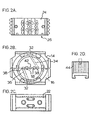
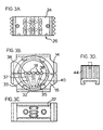
- the configuration of the channels 18 is variable but, as may be seen from Figures 2A and 3A, they may suitably be corrugated.
- Figure 1 which is included only as a rough picture of the tunnel does not show details of the vacuum forming means applicable to the mold surface of cavities 18. Such details are illustrated in Figures 2 and 3.
- FIG 1 shows the mold block halves 14, 16 as having bases 20, 22 (base 20 is referred to as a base because mold block half 14 is upside down with respect to mold block half 16).
- Bases 20, 22 include a T-channel extending from side to side of the aligned mold blocks. The T-channel mates with a T-bar 24 of a carrier block 26 for the respective mold block half 14, 16.
- the carrier blocks 26 are themselves carried by a longitudinal track of a conveyor of the travelling mold tunnel. For this purpose each carrier block 26 is provided with a groove 30 in its base surface for cooperation with the track.
- the bases 20, 22 of mold block halves 14, 16 may be formed unitarily with mold block halves 14, 16 or may be separate parts connected to the respective mold block halves through tongue and groove connections.
- the T-channel and T-bar 24 connections between the carrier blocks and the bases of the mold block halves 14, 16 may allow for the substitution of the mold blocks of the invention by conventional mold blocks having a single mold cavity therethrough when desired.
- Such conventional mold blocks may have a diameter comparable to the overall diameter of mold blocks 12 or may be somewhat smaller or larger.
- the mold blocks 12 may be slid off T-bars 24 and substituted by other inventive mold blocks of different size and/or having a different number or configuration of mold cavities 18 or having different arrangements of vacuum forming tube in mold cavities 18.
- Figures 2A, B, C and D illustrate provision of vacuum to cavities 18 from vacuum manifolds 32 in both mold halves 14, 16.
- the illustrated exemplary embodiment shows a vacuum channel 34 extending from top manifold 32 to one of the mold cavities 18, and a vacuum channel 36 extending from the bottom manifold 32 to the other of mold cavities 18.
- a longitudinally extending (i.e. parallel to the aligned mold blocks 12) subsidiary vacuum manifold 38 is provided for each channel 34, 36 adjacent the respective mold cavity 18.
- Communication of vacuum to the inner mold surface of cavities 18 from subsidiary manifolds 38 may be by conventional means. Seals may be provided to inhibit leakage of vacuum.
- sealing means 44 may be provided at the interface between mold blocks 12, sealing means 44 may be provided to minimize leakage of vacuum.
- FIGS 3A, B, C and D illustrate another embodiment. Similar reference numerals are used to indicate similar apparatus parts as in Figures 1 and 2.
- vacuum is drawn only from a vacuum manifold 32 in the lower mold block halves 16.
- three vacuum channels 33, 35, 37 may be provided to distribute vacuum to three subsidiary manifolds 38 located to each side of mold cavities 18.
- Shut-off valves 40 are provided to control the vacuum in each of channels 33, 35, 37 so that either one of mold cavities 18 may be isolated or the vacuum thereto may be otherwise controlled.
Landscapes
- Engineering & Computer Science (AREA)
- Manufacturing & Machinery (AREA)
- Mechanical Engineering (AREA)
- Blow-Moulding Or Thermoforming Of Plastics Or The Like (AREA)
- Moulds For Moulding Plastics Or The Like (AREA)
- Extrusion Moulding Of Plastics Or The Like (AREA)
Claims (4)
- Wandernder Formtunnel zur Vakuumformung von Profilrohren aus einem extrudierten Strang eines geschmolzenen thermoplastischen Materials, wobei der Tunnel eine Vielzahl von parallelen Formkammern (18) umfasst, wobei jede Formkammer (18) aus einer Mehrzahl von Formblöcken (12) gebildet ist, von denen jeder sich gegenüberstehenden Formblockhälften (14, 16) enthält, gekennzeichnet durch Einstellvorrichtungen zur unabhängigen Einstellung des Vakuums für jede der Formkammern (18), so dass der wandernde Formtunnel es ermöglicht, gleichzeitig in jeder der Formkammern parallele Rohre zu formen und, falls gewünscht, die nicht verwendete Formkammer oder die nicht verwendeten Formkammern (18) gegen das Vakuum abzudichten, um nicht in allen Formkammern Rohre zu formen, und durch eine Vielzahl von Vakuumkanälen (34, 36), von denen jeder einer Formkammer (18) zugeordnet ist, und durch einen getrennten Vakuumverteiler (32) für jeden der Vakuumkanäle (34, 36), wodurch jede der Formblockhälften (14, 16) nur mit einem der Vakuumkanäle (34, 36) und dem entsprechenden Vakuumverteiler (32) versehen ist.
- Wandernder Formtunnel zur Vakuumformung von Profilrohren aus einem extrudierten Strang eines geschmolzenen thermoplastischen Materials, wobei der Tunnel eine Vielzahl von parallelen Formkammern (18) umfasst, wobei jede Formkammer (18) aus einer Mehrzahl von Formblöcken (12) gebildet ist, von denen jeder sich gegenüberstehenden Formblockhälften (14, 16) enthält, gekennzeichnet durch Einstellvorrichtungen zur unabhängigen Einstellung des Vakuums für jede der Formkammern (18), so dass der wandernde Formtunnel es ermöglicht, gleichzeitig in jeder der Formkammern parallele Rohre zu formen und, falls gewünscht, die nicht verwendete Formkammer oder die nicht verwendeten Formkammern (18) gegen das Vakuum abzudichten, um nicht in allen Formkammern Rohre zu formen, und durch eine Vielzahl von Vakuumkanälen (33, 35, 37), von denen jeder einer Formkammer (18) zugeordnet ist, und durch einen gemeinsamen Vakuumverteiler (32) für alle Vakuumkanäle (33, 35, 37), wobei die Einstellvorrichtungen Ventilvorrichtungen zur unabhängigen Einstellung des Vakuums in jedem der Vakuumkanäle (33, 35, 37) umfassen, und alle Vakuumkanäle (33, 35, 37) und der gemeinsame Vakuumverteiler (32) in nur einer der Formblockhälften vorgesehen sind.
- Wandernder Formtunnel nach Anspruch 1 oder 2, gekennzeichnet durch gemeinsame Rohrprofil-Formkonfigurationen für alle Formkammern.
- Wandernder Formtunnel nach Anspruch 1 oder 2, gekennzeichnet durch verschiedene Rohrprofil-Formkonfigurationen für die Formkammern.
Applications Claiming Priority (3)
| Application Number | Priority Date | Filing Date | Title |
|---|---|---|---|
| GB9212684 | 1992-06-15 | ||
| GB929212684A GB9212684D0 (en) | 1992-06-15 | 1992-06-15 | A method and apparatus for forming profiled tubes |
| PCT/CA1993/000242 WO1993025373A1 (en) | 1992-06-15 | 1993-06-15 | Multi-cavity travelling mold tunnel for molding profiled pipe and mold block tunnels |
Publications (3)
| Publication Number | Publication Date |
|---|---|
| EP0648158A1 EP0648158A1 (de) | 1995-04-19 |
| EP0648158B1 EP0648158B1 (de) | 1996-12-18 |
| EP0648158B2 true EP0648158B2 (de) | 2004-12-29 |
Family
ID=10717128
Family Applications (1)
| Application Number | Title | Priority Date | Filing Date |
|---|---|---|---|
| EP93912511A Expired - Lifetime EP0648158B2 (de) | 1992-06-15 | 1993-06-15 | Wandernder mehrkammer-formtunnel zum giessen von profilrohr und formblock |
Country Status (8)
| Country | Link |
|---|---|
| US (1) | US5456589A (de) |
| EP (1) | EP0648158B2 (de) |
| JP (1) | JP3260757B2 (de) |
| CN (1) | CN1092017A (de) |
| CA (1) | CA2098325C (de) |
| DE (1) | DE69306786T3 (de) |
| GB (1) | GB9212684D0 (de) |
| WO (1) | WO1993025373A1 (de) |
Families Citing this family (12)
| Publication number | Priority date | Publication date | Assignee | Title |
|---|---|---|---|---|
| US5582849A (en) * | 1994-05-06 | 1996-12-10 | Lupke; Manfred A. A. | Travelling mold with mold block carriers |
| FR2748417B1 (fr) * | 1996-05-09 | 1998-06-12 | Corelco | Installation pour la fabrication par depression de corps tubulaires en matiere synthetique |
| DE69706055T2 (de) * | 1997-10-15 | 2001-11-22 | Corelco, Manziat | Vorrichtung zum Herstellen von rohrähnlichen Gegenständen aus Kunststoff unter Verwendung von Vacuum |
| US6033206A (en) * | 1998-03-06 | 2000-03-07 | Sofanou Inc. Of Michigan | Apparatus for producing molded plastic articles |
| US6089851A (en) * | 1998-03-26 | 2000-07-18 | Lupke; Manfred A. A. | Mold block with air flow control |
| AU2000222795A1 (en) * | 2000-02-04 | 2001-08-14 | Georg Fischer Disa A/S | Method and apparatus for producing casting moulds or mould parts |
| DE10148294C1 (de) | 2001-09-29 | 2003-01-16 | Unicor Rohrsysteme Gmbh | Formbackenhälfte für einen Corrugator zum Herstellen von Querrippenrohren |
| US20040084801A1 (en) * | 2002-11-04 | 2004-05-06 | Floyd Gregory S. | Method of manufacturing risers for shelving units |
| DE102013015306A1 (de) * | 2013-09-14 | 2015-03-19 | G & S Plast GmbH & Co. KG | Multichannel - Corrugator zur Herstellung von flexiblen Wellrohren, mit modularem Aufbau und mit parallel angeordneten und mit mindestens drei horizontal nebeneinander liegenden Formkanäle. |
| WO2025072185A1 (en) * | 2023-09-25 | 2025-04-03 | Advanced Drainage Systems, Inc. | Dual pipe manufacturing cell |
| DE212024000043U1 (de) * | 2023-09-25 | 2024-12-12 | Advanced Drainage Systems, Inc. | Doppelrohrfertigungszelle |
| CN118061404B (zh) * | 2024-04-22 | 2024-06-21 | 河南鹏庆塑业有限公司 | 一种聚乙烯管道成型设备及其使用方法 |
Citations (2)
| Publication number | Priority date | Publication date | Assignee | Title |
|---|---|---|---|---|
| DE3335850C2 (de) † | 1983-10-03 | 1986-11-06 | Fränkische Rohrwerke Gebrüder Kirchner GmbH & Co, 8729 Königsberg | Vorrichtung zum Herstellen von Kunststoffrohren |
| EP0464411A1 (de) † | 1990-07-06 | 1992-01-08 | Wilhelm Hegler | Vorrichtung zur Herstellung von Kunststoff-Rohren |
Family Cites Families (9)
| Publication number | Priority date | Publication date | Assignee | Title |
|---|---|---|---|---|
| FR70398E (fr) * | 1974-03-22 | 1959-04-06 | Electronique & Physique | Perfectionnements aux dispositifs de prise de vues de télévision et cinématographie |
| DE2542588C3 (de) * | 1975-09-24 | 1979-01-11 | The Upjohn Co., Kalamazoo, Mich. (V.St.A.) | Vorrichtung zum Unterdruck- oder Überdruckformen einer Folie |
| DE3027045A1 (de) * | 1980-07-17 | 1982-02-11 | Hegler, Wilhelm, 8730 Bad Kissingen | Flach-hohlkoerper, insbesondere lueftungs- und drainage- bzw. absorber-platte |
| US4325685A (en) * | 1980-09-12 | 1982-04-20 | Lupke Manfred Arno Alfred | Apparatus for producing thermoplastic tubing having interchangeable mold blocks |
| US4374079A (en) * | 1981-03-04 | 1983-02-15 | Hancor, Inc. | Method and apparatus for manufacturing expanded and layered semiround plastic tubings |
| US4668175A (en) * | 1985-05-23 | 1987-05-26 | Cosden Technology, Inc. | Apparatus for forming deep containers |
| DE3725286A1 (de) * | 1987-07-30 | 1989-02-09 | Wilhelm Hegler | Verfahren und vorrichtung zum herstellen eines rippen-rohres aus kunststoff |
| DE3737588C3 (de) * | 1987-11-05 | 1993-12-23 | Corma Inc | Verfahren zum Herstellen eines innen glatten, außen gerippten Rohres aus extrudierbarem Kunststoff sowie Vorrichtung zur Durchführung des Verfahrens |
| CA1298450C (en) * | 1988-09-16 | 1992-04-07 | Manfred A. A. Lupke | Suction applying molded blocks in pipe forming apparatus |
-
1992
- 1992-06-15 GB GB929212684A patent/GB9212684D0/en active Pending
-
1993
- 1993-06-14 CA CA002098325A patent/CA2098325C/en not_active Expired - Lifetime
- 1993-06-15 CN CN93108925A patent/CN1092017A/zh active Pending
- 1993-06-15 EP EP93912511A patent/EP0648158B2/de not_active Expired - Lifetime
- 1993-06-15 DE DE69306786T patent/DE69306786T3/de not_active Expired - Lifetime
- 1993-06-15 US US08/076,781 patent/US5456589A/en not_active Expired - Lifetime
- 1993-06-15 JP JP50098694A patent/JP3260757B2/ja not_active Expired - Fee Related
- 1993-06-15 WO PCT/CA1993/000242 patent/WO1993025373A1/en not_active Ceased
Patent Citations (2)
| Publication number | Priority date | Publication date | Assignee | Title |
|---|---|---|---|---|
| DE3335850C2 (de) † | 1983-10-03 | 1986-11-06 | Fränkische Rohrwerke Gebrüder Kirchner GmbH & Co, 8729 Königsberg | Vorrichtung zum Herstellen von Kunststoffrohren |
| EP0464411A1 (de) † | 1990-07-06 | 1992-01-08 | Wilhelm Hegler | Vorrichtung zur Herstellung von Kunststoff-Rohren |
Also Published As
| Publication number | Publication date |
|---|---|
| DE69306786T2 (de) | 1997-05-28 |
| JPH07507731A (ja) | 1995-08-31 |
| WO1993025373A1 (en) | 1993-12-23 |
| EP0648158B1 (de) | 1996-12-18 |
| DE69306786T3 (de) | 2005-06-23 |
| DE69306786D1 (de) | 1997-01-30 |
| US5456589A (en) | 1995-10-10 |
| EP0648158A1 (de) | 1995-04-19 |
| CN1092017A (zh) | 1994-09-14 |
| GB9212684D0 (en) | 1992-07-29 |
| CA2098325C (en) | 1999-11-16 |
| CA2098325A1 (en) | 1993-12-16 |
| JP3260757B2 (ja) | 2002-02-25 |
Similar Documents
| Publication | Publication Date | Title |
|---|---|---|
| EP0648158B2 (de) | Wandernder mehrkammer-formtunnel zum giessen von profilrohr und formblock | |
| US5002478A (en) | Improvements in suction applying mold blocks in pipe forming apparatus | |
| US5489201A (en) | Plastic tile corrugator and mold blocks | |
| EP0240838A3 (de) | Vorrichtung zum Formen von thermoplastischen Rohren | |
| US3529047A (en) | Method for continuous manufacture of corrugated plastic pipes | |
| KR830007272A (ko) | 동시 압출 장치 | |
| JPS5743852A (en) | Die for multiple extrusion of thermoplastic material | |
| US5429398A (en) | Coupling for ribbed pipe | |
| US5257924A (en) | Plastic tile corrugator | |
| US4452752A (en) | Method and apparatus for extruding thermoplastic shape | |
| US3298064A (en) | Apparatus for molding synthetic resin bodies | |
| US20050106281A1 (en) | System for molding corrugated pipe | |
| EP1066141B1 (de) | Formwerkzeug mit luftströmungseinstellung | |
| US4478563A (en) | Apparatus for upwardly extruding and cooling a thermoplastic resin multiple tube structure | |
| US3764245A (en) | Apparatus for producing light structural board of thermoplastic resin | |
| AU655793B2 (en) | Thermoplastic resin profile of cavitous structure-extrusion apparatus for obtaining and method of manufacture of a profile | |
| GB1383434A (en) | Moulding apparatus and method | |
| US20060062869A1 (en) | Molding apparatus with mold blocks having profiled face adjustment | |
| US3664789A (en) | Rotary extrusion die | |
| GB2116474A (en) | Method and apparatus for extruding a plastics jointing strip for building structures | |
| US6428734B1 (en) | Process for manufacturing injection moulded objects using side walls and plural injection points | |
| KR100484042B1 (ko) | 단열도관의제조방법 | |
| US6103175A (en) | Process for manufacturing injection moulded objects, device for carrying out such process and new moulded objects | |
| EP0291136B1 (de) | Kunststoffrohr mit festen Querrippen auf der äusseren Oberfläche, Formvorrichtung, Anlage mit einer solchen Vorrichtung und Verfahren zum Formen eines Kunststoffrohres | |
| EP4587251B1 (de) | Doppelrohrherstellungszelle |
Legal Events
| Date | Code | Title | Description |
|---|---|---|---|
| PUAI | Public reference made under article 153(3) epc to a published international application that has entered the european phase |
Free format text: ORIGINAL CODE: 0009012 |
|
| 17P | Request for examination filed |
Effective date: 19941122 |
|
| AK | Designated contracting states |
Kind code of ref document: A1 Designated state(s): DE FR GB IT |
|
| GRAG | Despatch of communication of intention to grant |
Free format text: ORIGINAL CODE: EPIDOS AGRA |
|
| GRAH | Despatch of communication of intention to grant a patent |
Free format text: ORIGINAL CODE: EPIDOS IGRA |
|
| 17Q | First examination report despatched |
Effective date: 19960529 |
|
| GRAH | Despatch of communication of intention to grant a patent |
Free format text: ORIGINAL CODE: EPIDOS IGRA |
|
| GRAA | (expected) grant |
Free format text: ORIGINAL CODE: 0009210 |
|
| AK | Designated contracting states |
Kind code of ref document: B1 Designated state(s): DE FR GB IT |
|
| REF | Corresponds to: |
Ref document number: 69306786 Country of ref document: DE Date of ref document: 19970130 |
|
| ITF | It: translation for a ep patent filed | ||
| ET | Fr: translation filed | ||
| PLBQ | Unpublished change to opponent data |
Free format text: ORIGINAL CODE: EPIDOS OPPO |
|
| PLBI | Opposition filed |
Free format text: ORIGINAL CODE: 0009260 |
|
| PLBF | Reply of patent proprietor to notice(s) of opposition |
Free format text: ORIGINAL CODE: EPIDOS OBSO |
|
| 26 | Opposition filed |
Opponent name: UNICOR ROHRSYSTEME GMBH Effective date: 19970828 |
|
| PLBF | Reply of patent proprietor to notice(s) of opposition |
Free format text: ORIGINAL CODE: EPIDOS OBSO |
|
| PLBQ | Unpublished change to opponent data |
Free format text: ORIGINAL CODE: EPIDOS OPPO |
|
| PLAB | Opposition data, opponent's data or that of the opponent's representative modified |
Free format text: ORIGINAL CODE: 0009299OPPO |
|
| R26 | Opposition filed (corrected) |
Opponent name: UNICOR ROHRSYSTEME GMBH Effective date: 19970828 |
|
| PLAW | Interlocutory decision in opposition |
Free format text: ORIGINAL CODE: EPIDOS IDOP |
|
| APAC | Appeal dossier modified |
Free format text: ORIGINAL CODE: EPIDOS NOAPO |
|
| APAE | Appeal reference modified |
Free format text: ORIGINAL CODE: EPIDOS REFNO |
|
| APAC | Appeal dossier modified |
Free format text: ORIGINAL CODE: EPIDOS NOAPO |
|
| REG | Reference to a national code |
Ref country code: GB Ref legal event code: IF02 |
|
| APBU | Appeal procedure closed |
Free format text: ORIGINAL CODE: EPIDOSNNOA9O |
|
| PUAH | Patent maintained in amended form |
Free format text: ORIGINAL CODE: 0009272 |
|
| STAA | Information on the status of an ep patent application or granted ep patent |
Free format text: STATUS: PATENT MAINTAINED AS AMENDED |
|
| 27A | Patent maintained in amended form |
Effective date: 20041229 |
|
| AK | Designated contracting states |
Kind code of ref document: B2 Designated state(s): DE FR GB IT |
|
| APAH | Appeal reference modified |
Free format text: ORIGINAL CODE: EPIDOSCREFNO |
|
| ET3 | Fr: translation filed ** decision concerning opposition | ||
| PGFP | Annual fee paid to national office [announced via postgrant information from national office to epo] |
Ref country code: GB Payment date: 20110628 Year of fee payment: 19 |
|
| PGFP | Annual fee paid to national office [announced via postgrant information from national office to epo] |
Ref country code: IT Payment date: 20110627 Year of fee payment: 19 |
|
| REG | Reference to a national code |
Ref country code: DE Ref legal event code: R082 Ref document number: 69306786 Country of ref document: DE Representative=s name: WUESTHOFF & WUESTHOFF PATENT- UND RECHTSANWAEL, DE |
|
| PGFP | Annual fee paid to national office [announced via postgrant information from national office to epo] |
Ref country code: DE Payment date: 20120627 Year of fee payment: 20 |
|
| PGFP | Annual fee paid to national office [announced via postgrant information from national office to epo] |
Ref country code: FR Payment date: 20120705 Year of fee payment: 20 |
|
| GBPC | Gb: european patent ceased through non-payment of renewal fee |
Effective date: 20120615 |
|
| PG25 | Lapsed in a contracting state [announced via postgrant information from national office to epo] |
Ref country code: IT Free format text: LAPSE BECAUSE OF NON-PAYMENT OF DUE FEES Effective date: 20120615 |
|
| PG25 | Lapsed in a contracting state [announced via postgrant information from national office to epo] |
Ref country code: GB Free format text: LAPSE BECAUSE OF NON-PAYMENT OF DUE FEES Effective date: 20120615 |
|
| REG | Reference to a national code |
Ref country code: DE Ref legal event code: R071 Ref document number: 69306786 Country of ref document: DE |
|
| PG25 | Lapsed in a contracting state [announced via postgrant information from national office to epo] |
Ref country code: DE Free format text: LAPSE BECAUSE OF EXPIRATION OF PROTECTION Effective date: 20130618 |