EP0648056A2 - Audio/video synchronization in a digital transmission system - Google Patents
Audio/video synchronization in a digital transmission system Download PDFInfo
- Publication number
- EP0648056A2 EP0648056A2 EP94115279A EP94115279A EP0648056A2 EP 0648056 A2 EP0648056 A2 EP 0648056A2 EP 94115279 A EP94115279 A EP 94115279A EP 94115279 A EP94115279 A EP 94115279A EP 0648056 A2 EP0648056 A2 EP 0648056A2
- Authority
- EP
- European Patent Office
- Prior art keywords
- audio
- signal
- responsive
- pts
- video
- Prior art date
- Legal status (The legal status is an assumption and is not a legal conclusion. Google has not performed a legal analysis and makes no representation as to the accuracy of the status listed.)
- Granted
Links
- 230000005540 biological transmission Effects 0.000 title description 7
- 238000012545 processing Methods 0.000 claims abstract description 41
- 230000005236 sound signal Effects 0.000 claims abstract description 25
- 230000006837 decompression Effects 0.000 claims description 18
- 230000001360 synchronised effect Effects 0.000 claims description 12
- 239000000872 buffer Substances 0.000 description 13
- 238000000034 method Methods 0.000 description 9
- 230000006870 function Effects 0.000 description 5
- 238000010586 diagram Methods 0.000 description 4
- 230000000694 effects Effects 0.000 description 4
- 238000005070 sampling Methods 0.000 description 4
- 238000006243 chemical reaction Methods 0.000 description 3
- 230000006835 compression Effects 0.000 description 3
- 238000007906 compression Methods 0.000 description 3
- 230000007774 longterm Effects 0.000 description 3
- 230000001143 conditioned effect Effects 0.000 description 2
- 238000001514 detection method Methods 0.000 description 2
- 230000036039 immunity Effects 0.000 description 2
- 239000000463 material Substances 0.000 description 2
- 230000008054 signal transmission Effects 0.000 description 2
- 230000001594 aberrant effect Effects 0.000 description 1
- 238000013459 approach Methods 0.000 description 1
- 238000004891 communication Methods 0.000 description 1
- 238000012937 correction Methods 0.000 description 1
- 239000013078 crystal Substances 0.000 description 1
- 230000001934 delay Effects 0.000 description 1
- 239000000835 fiber Substances 0.000 description 1
- 230000007274 generation of a signal involved in cell-cell signaling Effects 0.000 description 1
- 238000004519 manufacturing process Methods 0.000 description 1
- 230000007246 mechanism Effects 0.000 description 1
- 238000010606 normalization Methods 0.000 description 1
- 230000008520 organization Effects 0.000 description 1
- 230000000153 supplemental effect Effects 0.000 description 1
Images

Classifications
-
- H—ELECTRICITY
- H04—ELECTRIC COMMUNICATION TECHNIQUE
- H04N—PICTORIAL COMMUNICATION, e.g. TELEVISION
- H04N21/00—Selective content distribution, e.g. interactive television or video on demand [VOD]
- H04N21/40—Client devices specifically adapted for the reception of or interaction with content, e.g. set-top-box [STB]; Operations thereof
- H04N21/43—Processing of content or additional data, e.g. demultiplexing additional data from a digital video stream; Elementary client operations, e.g. monitoring of home network or synchronising decoder's clock; Client middleware
- H04N21/4302—Content synchronisation processes, e.g. decoder synchronisation
- H04N21/4305—Synchronising client clock from received content stream, e.g. locking decoder clock with encoder clock, extraction of the PCR packets
-
- H—ELECTRICITY
- H04—ELECTRIC COMMUNICATION TECHNIQUE
- H04N—PICTORIAL COMMUNICATION, e.g. TELEVISION
- H04N21/00—Selective content distribution, e.g. interactive television or video on demand [VOD]
- H04N21/40—Client devices specifically adapted for the reception of or interaction with content, e.g. set-top-box [STB]; Operations thereof
- H04N21/41—Structure of client; Structure of client peripherals
- H04N21/426—Internal components of the client ; Characteristics thereof
-
- H—ELECTRICITY
- H04—ELECTRIC COMMUNICATION TECHNIQUE
- H04N—PICTORIAL COMMUNICATION, e.g. TELEVISION
- H04N21/00—Selective content distribution, e.g. interactive television or video on demand [VOD]
- H04N21/40—Client devices specifically adapted for the reception of or interaction with content, e.g. set-top-box [STB]; Operations thereof
- H04N21/43—Processing of content or additional data, e.g. demultiplexing additional data from a digital video stream; Elementary client operations, e.g. monitoring of home network or synchronising decoder's clock; Client middleware
- H04N21/4302—Content synchronisation processes, e.g. decoder synchronisation
- H04N21/4307—Synchronising the rendering of multiple content streams or additional data on devices, e.g. synchronisation of audio on a mobile phone with the video output on the TV screen
- H04N21/43072—Synchronising the rendering of multiple content streams or additional data on devices, e.g. synchronisation of audio on a mobile phone with the video output on the TV screen of multiple content streams on the same device
-
- H—ELECTRICITY
- H04—ELECTRIC COMMUNICATION TECHNIQUE
- H04N—PICTORIAL COMMUNICATION, e.g. TELEVISION
- H04N21/00—Selective content distribution, e.g. interactive television or video on demand [VOD]
- H04N21/40—Client devices specifically adapted for the reception of or interaction with content, e.g. set-top-box [STB]; Operations thereof
- H04N21/43—Processing of content or additional data, e.g. demultiplexing additional data from a digital video stream; Elementary client operations, e.g. monitoring of home network or synchronising decoder's clock; Client middleware
- H04N21/434—Disassembling of a multiplex stream, e.g. demultiplexing audio and video streams, extraction of additional data from a video stream; Remultiplexing of multiplex streams; Extraction or processing of SI; Disassembling of packetised elementary stream
- H04N21/4341—Demultiplexing of audio and video streams
-
- H—ELECTRICITY
- H04—ELECTRIC COMMUNICATION TECHNIQUE
- H04N—PICTORIAL COMMUNICATION, e.g. TELEVISION
- H04N21/00—Selective content distribution, e.g. interactive television or video on demand [VOD]
- H04N21/40—Client devices specifically adapted for the reception of or interaction with content, e.g. set-top-box [STB]; Operations thereof
- H04N21/43—Processing of content or additional data, e.g. demultiplexing additional data from a digital video stream; Elementary client operations, e.g. monitoring of home network or synchronising decoder's clock; Client middleware
- H04N21/439—Processing of audio elementary streams
- H04N21/4392—Processing of audio elementary streams involving audio buffer management
-
- H—ELECTRICITY
- H04—ELECTRIC COMMUNICATION TECHNIQUE
- H04N—PICTORIAL COMMUNICATION, e.g. TELEVISION
- H04N21/00—Selective content distribution, e.g. interactive television or video on demand [VOD]
- H04N21/80—Generation or processing of content or additional data by content creator independently of the distribution process; Content per se
- H04N21/85—Assembly of content; Generation of multimedia applications
- H04N21/854—Content authoring
- H04N21/8547—Content authoring involving timestamps for synchronizing content
-
- H—ELECTRICITY
- H04—ELECTRIC COMMUNICATION TECHNIQUE
- H04N—PICTORIAL COMMUNICATION, e.g. TELEVISION
- H04N5/00—Details of television systems
- H04N5/04—Synchronising
-
- H—ELECTRICITY
- H04—ELECTRIC COMMUNICATION TECHNIQUE
- H04N—PICTORIAL COMMUNICATION, e.g. TELEVISION
- H04N5/00—Details of television systems
- H04N5/44—Receiver circuitry for the reception of television signals according to analogue transmission standards
- H04N5/60—Receiver circuitry for the reception of television signals according to analogue transmission standards for the sound signals
- H04N5/602—Receiver circuitry for the reception of television signals according to analogue transmission standards for the sound signals for digital sound signals
-
- H—ELECTRICITY
- H04—ELECTRIC COMMUNICATION TECHNIQUE
- H04N—PICTORIAL COMMUNICATION, e.g. TELEVISION
- H04N7/00—Television systems
- H04N7/24—Systems for the transmission of television signals using pulse code modulation
- H04N7/52—Systems for transmission of a pulse code modulated video signal with one or more other pulse code modulated signals, e.g. an audio signal or a synchronizing signal
- H04N7/54—Systems for transmission of a pulse code modulated video signal with one or more other pulse code modulated signals, e.g. an audio signal or a synchronizing signal the signals being synchronous
- H04N7/56—Synchronising systems therefor
Definitions
- This invention relates to a method and apparatus for synchronizing the audio and video component signals at an audio/video signal decompression apparatus
- Audio and video (A/V) transmission and reception requires that the audio and video components be properly synchronized.
- EIA standards RS-250-B limit the time differential between associated audio and video signals to 25 ms. lead or 40 ms. lag time.
- Film standards limit the time differential of associated audio and video to ⁇ 1/2 frame, which corresponds to 20.8 ms. An acceptable goal for source to viewer A/V synchronization is therefore a time differential of ⁇ 20 ms.
- Digital communication systems typically time-multiplex associated signal components over a single channel. Such multiplexing is common among A/V transmission systems proposed and implemented for cable, fiber, terrestrial and satellite applications.
- the time multiplexing of the signal components may destroy their natural time relationships between the transmission and display of the information. Therefore, time critical components of the transmitted component signals may be associated with a time reference before being multiplexed. This is referred to as "stamping" the information, and timing samples are referred to as time stamps.
- the receiver may then output the respective components in time relative to their respective time stamps. However to accomplish this the receiver must maintain a very precise local time reference, which is synchronous to the encoder time reference.
- the receiver must be tightly coupled to the time base of the transmitter is to insure that the output of real time data matches that of the input to the receiver. If the receiver provides (displays) the data too rapidly, buffers in the receiver may underflow resulting in an interruption of the output signal. If the receiver outputs the data too slowly , the buffers may overflow (assuming finite rate buffers) resulting is a loss of data.
- the receiver is synchronized to the transmitter by supplemental time stamps (system clock references, SCR) associated with predetermined packets of transmitted information.
- SCR system clock references
- the SCR codes are generated by sampling a modulo 2 N counter (N ⁇ 32) which counts a substantially constant frequency crystal clock at the transmitter.
- the receiver incorporates a phase locked loop which has a free running frequency substantially equal to the frequency of the clock in the transmitter.
- the receiver clock (local clock) is also counted modulo 2 N , and each time a SCR arrives at the receiver the local counter is sampled to provide a local clock reference or LCR.
- Video signal coded according to the MPEG standard includes presentation time stamps, PTS vid , which are synchronized to the input video frames.
- the respective PTS vid indicate the relative times that the respective frames are to be displayed at the receiver, nominally 30 Hz, for NTSC source material.
- Associated audio is also encoded with presentation time stamps PTS aud based on the same time base as the system time and which time stamps are placed in an MPEG system packet layer encompassing the encoded audio data.
- An audio system packet layer may contain several "frames" of audio data and respective frames equal, in this example, 24 ms. of original audio data. Audio frames are approximately six times the duration of a (127 byte) transport packet.
- a receiver for decoding associated video and audio information components transmitted in mutually exclusive "frames" of data with respective time stamps PTS vid and PTS aud respectively includes a controller which is responsive to the respective received time stamps to provide coarse synchronization by delaying or skipping respective frames of one or the other of the components to approximately time align the two components. Fine synchronization is provided by adjusting the processing or clock frequency of the audio signal processor independent of the video processor. The control for the frequency adjustment is related to the difference between audio and video time stamps.
- FIGURE 1 is a block diagram of audio/video compression apparatus.
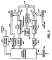
- FIGURE 2 is a block diagram of a audio/video decompression apparatus embodying the present invention.
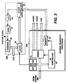
- FIGURE 3 s a block diagram of apparatus for providing the receiver system clock signal having substantially the same rate as the system clock of the compression apparatus.
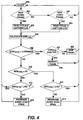
- FIGURE 4 is a flow chart of the operation of the FIGURE 2 apparatus.
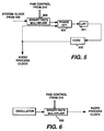
- FIGURES 5 and 6 are block diagrams of alternative audio processing clock signal generation which may be implemented for element 215 in FIGURE 2.
- FIGURE 1 illustrates a typical system in which the invention may be practiced, which system is a compressed digital video signal transmission arrangement.
- video signal from a source 10 is applied to a video signal compression element 11 which may include a motion compensated predictive encoder utilizing discrete cosine transforms.
- Compressed video signal from the element 11 is coupled to a formatter 12.
- the formatter arranges the compressed video signal and other ancillary data according to some signal protocol such as MPEG, a standard developed by the International Organization for Standardization (Organisation Internationale De Normalisation).
- the standardized signal is applied to a transport processor 13, which divides the signal into packets of data and adds certain overhead to provide some noise immunity for the transmission purposes.
- the transport packets which normally occur at a non-uniform rate are applied to a rate buffer 14 which provides output data at a relatively constant rate conducive to efficient use of a relatively narrow bandwidth transmission channel.
- the buffered data is coupled to a modem 15 which performs the signal transmission.
- a system clock 22 provides clocking signal to operate much of the apparatus, at least including the transport processor. This clock will operate at a fixed frequency such as 27 MHz for example. As shown herein, however, it is used to generate timing information.
- the system clock is coupled to the clock input of a counter 23 which may be arranged to count modulo 230 , for example.
- the count values output by the counter are applied to two latches 24 and 25.
- the latch 24 is conditioned by the video source to latch count values on the occurrence of respective frame intervals. These count values are denoted presentation time stamps, PTS's, and are included in the compressed video signal stream by the formatter 12, and are used by the receiver to provide lip-synchronization of associated audio and video information.
- the latch 25 is conditioned by the transport processor 13 (or the system controller 21) to latch count values according to a predetermined schedule. These count values are denoted system clock references, SCR's, and are embedded as auxiliary data within respective auxiliary transport packets.
- Audio signal associated with the video signal from source 10 is applied to an audio signal compressor 18.
- the compressor 18 provides frame sampling pulses (independent of video frames) to control a latch 19. Responsive to the sampling pulses, the latch 19 captures count values provided by the counter 23. These latched values correspond to audio presentation time stamps PTS aud .
- the PTS aud are incorporated in the compressed audio signal provided by the compressor 18.
- the compressed audio signal is coupled to a transport processor 17 which divides the signal into packets of data and adds certain overhead to provide some noise immunity for transmission purposes.
- the audio transport packets provided by the processor 17 are coupled to a multiplexor 16 which time division multiplexes the audio and video transport packets. In the figure, separate transport processors are shown in the audio and video signal processing channels. For systems wherein the data rate is moderate, the functions of the two transport processors and the multiplexor 16 may be subsumed in a single transport processor.
- the system controller 21 is a variable state machine programmed to coordinate the various processing elements. Note that the controller 21, the compressors 11 and 18, the transport processors 13 and 17, and the rate buffer 14 may or may not operate synchronously via a common clocking arrangement as long as proper handshaking is provided between processing elements. However, the two compressors both derive PTS values from the same reference counter 23, thus a precise timing relationship between the two compressed signals is provided in the compressed output signal.
- FIGURE 2 illustrates an exemplary receiver apparatus embodying the invention wherein the modem 200 performs the inverse function of the modem 15 and the rate buffers 204 and 206 perform, in effect, the inverse function of the rate buffer 14.
- a single inverse transport processor 202 is indicated, which processor divides respective transport packets by service and allocates the respective data to the appropriate processing channel. In so doing the respective transport packet signal payloads are separated from the auxiliary data, with the respective payloads being applied to the appropriate processing channel and the auxiliary data applied to the system controller 210.
- a separate transport processor may be included in each processing channel and arranged to recognize and process only data associated with the respective channels.
- Compressed video data from the inverse transport processor 202 is applied to the rate buffer 204, which provides compressed video signal according to the system protocol to the decompressor 214.
- the rate buffer 204 accepts data at a bursty or inconsistent rate, and provides data on demand to the decompressor 214.
- the decompressor responsive to the compressed video signal, generates non-compressed video signal for display or for storage etc., in appropriate display or storage devices (not shown).
- Compressed audio data from the inverse transport processor 202 is applied to the rate buffer 206, which provides compressed audio signal according to the system protocol to the audio decompressor 212.
- the decompressor, 212 responsive to the compressed audio signal generates non-compressed audio signal for reproduction or for storage etc., in appropriate speakers or storage devices (not shown).
- the inverse processor 202 also provides SCR's from the auxiliary transport data, and control signals to a system clock generator 208.
- the clock generator responsive to these signals generates a system clock signal synchronous with at least the transport processor operation. This system clock signal is applied to the receiver system controller 210 to control the timing of appropriate processing elements.
- FIG. 3 illustrates details of an exemplary clock regenerator 208.
- Data from the receiver modem 200 is coupled to the inverse transport processor 202', including an auxiliary packet detector 31.
- the inverse transport processor 202' separates transport header data from the respective transport packet payloads. Responsive to the transport header data, the processor 202' applies audio and video signal payloads to, for example, respective decompression apparatus (not shown), and auxiliary data (designated as AUX) to the appropriate auxiliary data processing elements (not shown).
- AUX auxiliary data
- the SCR's residing within the auxiliary data are routed and stored in a memory element, 34.
- the auxiliary packet detector 31 which may be a matched filter arranged to recognize the codewords designating an auxiliary transport packet containing a SCR, produces a control pulse on the occurrence of transport packets containing such data.
- the control pulse is utilized to capture and store within a latch 35, the count value currently exhibited by the local counter 36 at a time precisely related to the time of detection.
- the local counter 36 is arranged to count pulses provided by a voltage controlled oscillator 37.
- the counter 36 is arranged to count modulo M which may be, but is not necessarily, the same number as its counterpart counter in the encoder (counter 23). If M differs from N the difference may be accommodated in the error equation.
- the voltage controlled oscillator 37 is controlled by a low pass filtered 38 error signal provided by a clock controller 39.
- the error signal is generated in the following fashion. Let the SCR arriving at time n be designated SCR n and the local count value concurrently captured in the latch 35 be designated LCR n .
- the clock controller reads the successive values of SCR's and LCR's and forms an error signal E proportional to the differences E ⁇
- the error signal E is utilized to condition the voltage controlled oscillator 37 to a frequency tending to equalize the differences. As indicated previously, negative differences exhibited due to modulo counter wrap around, may be ignored.
- the error signal produced by the clock controller 39 may be in the form of a pulse width modulated signal, which may be rendered into an analog error signal by implementing the low pass filter 38 in analog components.
- LTE Long term error
- the error signals E and LTE will vary in discrete steps. As such, once the system is "synchronized" the error signal will dither one unit about the null point.
- the preferred method of synchronization is to initiate control of the voltage controlled oscillator using the error signal E until a one unit dither occurs in the error signal E, and then to switch to the use of the long term error signal LTE to control the voltage controlled oscillator.
- the system clock signal provided by the VCXO 37 may be utilized to operate at least the transport processor and rate buffers. Since it is synchronized at least in frequency with the encoder system clock, the possibility of rate buffer overflow or underflow due to clock timing errors is substantially non-existent.
- a presentation time stamp PTS vid is included in the compressed video signal associated with predetermined video data.
- the PTS vid is indicative of the relative time that the associated video is to be displayed.
- the compressed audio signal includes presentation time stamps PTS aud associated with audio to be reproduced at times related to the respective PTS aud .
- the PTS aud and PTS vid may not be compared directly to provide A/V synchronization because the respective samples were determined at different instants.
- the respective PTS values are compared to a continuous time base which is the receiver clock provided by the VCXO 37. This is done by sampling local time stamps of the count values LCR.
- the LCR When data associated with an associated PTS is presented, The LCR is sampled. For example, The audio decompressor 212 issues a PTS aud when a respective audio frame is output for reproduction. At these times a control signal conditions the latch 220 to sample the LCR, the values of which will be designated LAS, for local audio stamp. Similarly when the video decompressor provides a video frame for display, it provides a PTS vid and a control pulse to condition a latch 222 to store the current value of the LCR. These LCR values are designated LVS for local video stamps.
- the signals ⁇ V-PTS and ⁇ A-PTS are coupled to respective input terminals of a further subtractor, 219, which develops an A/V synchronization error signal ERR PTS according to the relation;
- ERR PTS ⁇ V-PTS - ⁇ A-PTS
- Synchronization of the audio and video requires that the A/V synchronization error be driven to zero. This indicates that when the difference in the values of the corresponding audio and video PTS's equals the time, in units of the local reference, between the occurrence of the corresponding PTS's, the audio and video signal will be in synchronization.
- Two mechanisms may be used to adjust the A/V synchronization based upon the error signal ERR PTS ; skips and repeats of data sections and conversion clock deviation. Skipping fixed intervals or "frames" of audio advances the audio data stream by a fixed interval relative to the video signal. Repeating (or muting without consuming data) delays the audio data stream by fixed intervals relative to the video signal. Skipping and repeating audio frames is audible under many conditions, and therefore is only utilized for coarse adjustment of synchronization. Even so, brief skipping or repeating may be preferable to discernible audio/video synchronization errors.
- the error signal ERR PTS is applied to a filter and processing element 216.
- a filter function therein smoothes the signal ERR PTS to minimize aberrant effects that might otherwise be generated by signal noise.
- the processing function in the element 216 then examines the smoothed error signal and determines whether a skip/repeat of audio should be utilized to effect coarse synchronization of the audio and video signals and/or whether an adjustment to the audio processing frequency should be utilized to effect fine synchronization. If a coarse synchronization adjustment is determined to be necessary, the processor 216 provides a control signal to the audio decompressor 212 to condition the decompressor to skip or repeat the current decompressed audio frame. Alternatively, or in addition to the coarse adjustment, if a fine adjustment is determined to be necessary, the processor 216 provides a control signal to the audio time base 215 to adjust the frequency of the audio processing clock signal.
- the processing algorithm is detailed in the flow chart of FIGURE 4.
- the magnitude of the error signal is examined 406 to determine if it is greater than one half an audio frame interval. If it is greater than one half an audio frame interval, the error signal is checked for polarity 407. If the polarity is positive, the current audio frame is repeated 409. If it is negative the current audio frame is skipped 408. After skipping or repeating a frame the system iterates back to the start position to wait for the next occurrence of PTS's.
- the error is examined to determine if it is greater than zero 410. If the error is greater than zero, the error is checked 412 to determine if it is less than the previous error signal. If it is less than the previous error signal, this is an indication that the system is converging toward synchronization, and the synchronization control parameters are not changed. The system returns to the start position to wait for the next PTS's. Conversely, if the error has increased over the previous error signal, the audio system processing clock is adjusted to lessen its frequency 414.
- step 410 if the error is less than zero (negative), it is checked 411 to determine whether it is greater than the previous error signal. If it is greater than the previous error signal, this is also an indication that the system is converging toward synchronization, and the synchronization control parameters are not changed. Alternatively if the current error signal is less than the previous error signal the system is moving further out of synchronization and the audio processing clock frequency is increased 413. After processing steps 412 and 413 the system returns to wait for the next occurrence of PTS's. It will be noted in this example, that the system performs only coarse adjustments via skipping or repeating audio frames until the A/V synchronization error is reduced to less than one half an audio frame interval.
- the filtered error signal is compared against a predetermined threshold related to the size of respective audio frames. If the error signal is less than the threshold, indicative that the audio-video timing error is less than an audio frame, the error signal is coupled to the audio time base circuit 215, wherein it is utilized to adjust the frequency of the audio signal processing (decompression) clock. Alternatively, if the error signal is greater than the threshold, the error signal may be divided by the audio frame interval to determine the number of audio frames that the audio and video signal are misaligned. The integer portion of the quotient is applied to the audio decompressor to condition the audio decompressor to skip or repeat that number of audio frames. The polarity of the error signal will determine whether audio frames should be skipped or repeated. Nominally the decompressed data is arranged in a buffer memory prior to being output, hence skipping or repeating audio frames is a simple matter of controllably enabling the memory read/write commands.
- the fractional portion of the quotient is coupled to the audio time base circuit 215, where it is utilized to adjust the audio processing clock to fine tune the A/V synchronization.
- the rate of production of audio PTS's is proportional to the processing speed of the audio decompressor.
- the processing speed of the audio decompressor is directly proportional to the frequency of the clock signal used to operate the audio decompressor. If the clock frequency of the audio decompressor is independent of the clock used to operate the video decompressor, and is finely adjustable then the relative rate of occurrence of the audio and video PTS's can be adjusted and the A/V finely synchronized.
- FIGURE 5 is a first embodiment of circuitry for generating an adjustable audio processing clock signal.
- a voltage controlled oscillator, 503 is connected in a phase locked loop including elements 500 and 501.
- the output of the oscillator is coupled to one input of a phase detector 500.
- the system clock is coupled to a second input of the phase detector 500 via a binary rate multiplier 505.
- a phase error signal developed by the phase detector is low pass filtered in filter 501.
- This smoothed phase error signal is coupled to the control input terminal of the oscillator to condition the oscillator to oscillate at the same frequency and phase as the output of the binary rate multiplier.
- the system clock frequency is approximately 27 MHz and the desired audio processing clock frequency is approximately 1/380 of the 27 MHz signal.
- a control signal from the process element 216 is coupled to a control input port of the binary rate multiplier to control its output frequency.
- This control signal is selected to represent a nominal division ratio of 1/380, but modulates about this value so as to condition the output of the binary rate multiplier to produce an output frequency commensurate with the instantaneous desired audio processing rate.
- FIGURE 6 illustrates a second example of adjustable audio processing clock generation.
- a constant clock frequency from the system clock generator 208 or some other stable oscillator, is applied to one input of a binary rate multiplier 600.
- the binary rate multiplier is controlled by a control signal from the process element 216 to generate a nominal desired audio processing clock frequency. Responsive to the A/V error signal the process element 216 alters this control signal to condition the binary rate multiplier to either increase or decrease the nominal audio processing clock frequency.
- a further alternative audio signal processing rate changing apparatus may include an oscillator for providing a nominal maximum audio processing clock frequency and a gating circuit.
- the oscillator is coupled to the audio processing circuit via the gating circuit.
- the gating circuit is controlled by the process element 216 to excise ones of the oscillator output pulses to provide, on average, a desired audio processing clock frequency.
- An alternative embodiment of the synchronizing apparatus may be arranged to skip or repeat video frames to effect synchronization.
- video frames may be skipped for the audio leading (lagging) video and audio frames may be skipped for the audio frames lagging (leading) video.
- the audio frames are skipped/repeated for audio lagging and leading video respectively.
Landscapes
- Engineering & Computer Science (AREA)
- Multimedia (AREA)
- Signal Processing (AREA)
- Computer Security & Cryptography (AREA)
- Compression Or Coding Systems Of Tv Signals (AREA)
- Synchronisation In Digital Transmission Systems (AREA)
- Television Receiver Circuits (AREA)
- Two-Way Televisions, Distribution Of Moving Picture Or The Like (AREA)
- Television Signal Processing For Recording (AREA)
- Details Of Television Systems (AREA)
- Television Systems (AREA)
- Synchronizing For Television (AREA)
- Transmission Systems Not Characterized By The Medium Used For Transmission (AREA)
- Reduction Or Emphasis Of Bandwidth Of Signals (AREA)
Abstract
Description
- This invention relates to a method and apparatus for synchronizing the audio and video component signals at an audio/video signal decompression apparatus
- Audio and video (A/V) transmission and reception requires that the audio and video components be properly synchronized. EIA standards RS-250-B limit the time differential between associated audio and video signals to 25 ms. lead or 40 ms. lag time. Film standards limit the time differential of associated audio and video to ±1/2 frame, which corresponds to 20.8 ms. An acceptable goal for source to viewer A/V synchronization is therefore a time differential of ±20 ms.
- Digital communication systems typically time-multiplex associated signal components over a single channel. Such multiplexing is common among A/V transmission systems proposed and implemented for cable, fiber, terrestrial and satellite applications. The time multiplexing of the signal components may destroy their natural time relationships between the transmission and display of the information. Therefore, time critical components of the transmitted component signals may be associated with a time reference before being multiplexed. This is referred to as "stamping" the information, and timing samples are referred to as time stamps. The receiver may then output the respective components in time relative to their respective time stamps. However to accomplish this the receiver must maintain a very precise local time reference, which is synchronous to the encoder time reference.
- One reason that the receiver must be tightly coupled to the time base of the transmitter is to insure that the output of real time data matches that of the input to the receiver. If the receiver provides (displays) the data too rapidly, buffers in the receiver may underflow resulting in an interruption of the output signal. If the receiver outputs the data too slowly , the buffers may overflow (assuming finite rate buffers) resulting is a loss of data.
- In one proposed system the receiver is synchronized to the transmitter by supplemental time stamps (system clock references, SCR) associated with predetermined packets of transmitted information. The timing of the capture of the time stamps, SCR, bear no relation to presentation time stamps (PTS) which are related to the video data, other than by virtue of being derived from the same counter. The SCR codes are generated by sampling a
modulo 2N counter (N ≧ 32) which counts a substantially constant frequency crystal clock at the transmitter. The receiver incorporates a phase locked loop which has a free running frequency substantially equal to the frequency of the clock in the transmitter. The receiver clock (local clock) is also countedmodulo 2N, and each time a SCR arrives at the receiver the local counter is sampled to provide a local clock reference or LCR. No attempt is made to force the LCR to equal the SCR. Rather the local clock is adjusted based upon processing changes in the difference between the LCR and SCR time stamps. An error signal is generated according to the relation

The signal ERR is utilized to control the local clock frequency. Via this process the LCR can be made arbitrarily close to the transmitter clock frequency. Note that since both the system and local clocks are counting modulo N, they periodically wrap around. On these occurrences the respective terms SCRn-SCRn-1and LCRn -LCRn-1will be negative and erroneous. The system monitors the polarity of the respective differences and when one of the differences is negative the difference is ignored. - Video signal coded according to the MPEG standard includes presentation time stamps, PTSvid, which are synchronized to the input video frames. The respective PTSvid indicate the relative times that the respective frames are to be displayed at the receiver, nominally 30 Hz, for NTSC source material. Associated audio is also encoded with presentation time stamps PTSaud based on the same time base as the system time and which time stamps are placed in an MPEG system packet layer encompassing the encoded audio data. An audio system packet layer may contain several "frames" of audio data and respective frames equal, in this example, 24 ms. of original audio data. Audio frames are approximately six times the duration of a (127 byte) transport packet. (Information to be transmitted, audio, video, data, etc. are segmented into respective transport packets of predetermined size, with a variety of control words appended, to provide an extra layer of error correction/detection and synchronization.) In addition, according to the MPEG protocol, the number of audio frames per MPEG system layer is a variable. Hence there may be little or no correlation between the video PTSvid and audio PTSaud presentation time stamps for associated audio and video source material. Thus synchronizing the audio and video components is difficult if one attempts to do so by comparing the PTSvid with the PTSaud. It is an object of the present invention to simplify the process of synchronizing associated audio and video components.
- A receiver for decoding associated video and audio information components transmitted in mutually exclusive "frames" of data with respective time stamps PTSvid and PTSaud respectively, includes a controller which is responsive to the respective received time stamps to provide coarse synchronization by delaying or skipping respective frames of one or the other of the components to approximately time align the two components. Fine synchronization is provided by adjusting the processing or clock frequency of the audio signal processor independent of the video processor. The control for the frequency adjustment is related to the difference between audio and video time stamps.
- FIGURE 1 is a block diagram of audio/video compression apparatus.
- FIGURE 2 is a block diagram of a audio/video decompression apparatus embodying the present invention.
- FIGURE 3 s a block diagram of apparatus for providing the receiver system clock signal having substantially the same rate as the system clock of the compression apparatus.
- FIGURE 4 is a flow chart of the operation of the FIGURE 2 apparatus.
- FIGURES 5 and 6 are block diagrams of alternative audio processing clock signal generation which may be implemented for
element 215 in FIGURE 2. - FIGURE 1 illustrates a typical system in which the invention may be practiced, which system is a compressed digital video signal transmission arrangement. In this system, video signal from a
source 10 is applied to a videosignal compression element 11 which may include a motion compensated predictive encoder utilizing discrete cosine transforms. Compressed video signal from theelement 11 is coupled to aformatter 12. The formatter arranges the compressed video signal and other ancillary data according to some signal protocol such as MPEG, a standard developed by the International Organization for Standardization (Organisation Internationale De Normalisation). The standardized signal is applied to atransport processor 13, which divides the signal into packets of data and adds certain overhead to provide some noise immunity for the transmission purposes. The transport packets, which normally occur at a non-uniform rate are applied to arate buffer 14 which provides output data at a relatively constant rate conducive to efficient use of a relatively narrow bandwidth transmission channel. The buffered data is coupled to amodem 15 which performs the signal transmission. - A
system clock 22 provides clocking signal to operate much of the apparatus, at least including the transport processor. This clock will operate at a fixed frequency such as 27 MHz for example. As shown herein, however, it is used to generate timing information. The system clock is coupled to the clock input of acounter 23 which may be arranged to count modulo 2³⁰ , for example. The count values output by the counter are applied to twolatches latch 24 is conditioned by the video source to latch count values on the occurrence of respective frame intervals. These count values are denoted presentation time stamps, PTS's, and are included in the compressed video signal stream by theformatter 12, and are used by the receiver to provide lip-synchronization of associated audio and video information. Thelatch 25 is conditioned by the transport processor 13 (or the system controller 21) to latch count values according to a predetermined schedule. These count values are denoted system clock references, SCR's, and are embedded as auxiliary data within respective auxiliary transport packets. - Audio signal associated with the video signal from
source 10 is applied to anaudio signal compressor 18. Thecompressor 18 provides frame sampling pulses (independent of video frames) to control alatch 19. Responsive to the sampling pulses, thelatch 19 captures count values provided by thecounter 23. These latched values correspond to audio presentation time stamps PTSaud. The PTSaud are incorporated in the compressed audio signal provided by thecompressor 18. The compressed audio signal is coupled to atransport processor 17 which divides the signal into packets of data and adds certain overhead to provide some noise immunity for transmission purposes. The audio transport packets provided by theprocessor 17 are coupled to amultiplexor 16 which time division multiplexes the audio and video transport packets. In the figure, separate transport processors are shown in the audio and video signal processing channels. For systems wherein the data rate is moderate, the functions of the two transport processors and themultiplexor 16 may be subsumed in a single transport processor. - The
system controller 21 is a variable state machine programmed to coordinate the various processing elements. Note that thecontroller 21, thecompressors transport processors rate buffer 14 may or may not operate synchronously via a common clocking arrangement as long as proper handshaking is provided between processing elements. However, the two compressors both derive PTS values from thesame reference counter 23, thus a precise timing relationship between the two compressed signals is provided in the compressed output signal. - FIGURE 2 illustrates an exemplary receiver apparatus embodying the invention wherein the
modem 200 performs the inverse function of themodem 15 and the rate buffers 204 and 206 perform, in effect, the inverse function of therate buffer 14. In FIGURE 2 a singleinverse transport processor 202 is indicated, which processor divides respective transport packets by service and allocates the respective data to the appropriate processing channel. In so doing the respective transport packet signal payloads are separated from the auxiliary data, with the respective payloads being applied to the appropriate processing channel and the auxiliary data applied to thesystem controller 210. In an alternative arrangement a separate transport processor may be included in each processing channel and arranged to recognize and process only data associated with the respective channels. - Compressed video data from the
inverse transport processor 202 is applied to therate buffer 204, which provides compressed video signal according to the system protocol to thedecompressor 214. Therate buffer 204 accepts data at a bursty or inconsistent rate, and provides data on demand to thedecompressor 214. The decompressor, responsive to the compressed video signal, generates non-compressed video signal for display or for storage etc., in appropriate display or storage devices (not shown). - Compressed audio data from the
inverse transport processor 202 is applied to therate buffer 206, which provides compressed audio signal according to the system protocol to theaudio decompressor 212. The decompressor, 212, responsive to the compressed audio signal generates non-compressed audio signal for reproduction or for storage etc., in appropriate speakers or storage devices (not shown). - The
inverse processor 202 also provides SCR's from the auxiliary transport data, and control signals to asystem clock generator 208. The clock generator responsive to these signals generates a system clock signal synchronous with at least the transport processor operation. This system clock signal is applied to thereceiver system controller 210 to control the timing of appropriate processing elements. - Figure 3 illustrates details of an
exemplary clock regenerator 208. Data from thereceiver modem 200 is coupled to the inverse transport processor 202', including anauxiliary packet detector 31. The inverse transport processor 202' separates transport header data from the respective transport packet payloads. Responsive to the transport header data, the processor 202' applies audio and video signal payloads to, for example, respective decompression apparatus (not shown), and auxiliary data (designated as AUX) to the appropriate auxiliary data processing elements (not shown). The SCR's residing within the auxiliary data are routed and stored in a memory element, 34. - The
auxiliary packet detector 31, which may be a matched filter arranged to recognize the codewords designating an auxiliary transport packet containing a SCR, produces a control pulse on the occurrence of transport packets containing such data. The control pulse is utilized to capture and store within alatch 35, the count value currently exhibited by thelocal counter 36 at a time precisely related to the time of detection. Thelocal counter 36 is arranged to count pulses provided by a voltage controlledoscillator 37. Thecounter 36 is arranged to count modulo M which may be, but is not necessarily, the same number as its counterpart counter in the encoder (counter 23). If M differs from N the difference may be accommodated in the error equation. - The voltage controlled
oscillator 37 is controlled by a low pass filtered 38 error signal provided by aclock controller 39. The error signal is generated in the following fashion. Let the SCR arriving at time n be designated SCRn and the local count value concurrently captured in thelatch 35 be designated LCRn. The clock controller reads the successive values of SCR's and LCR's and forms an error signal E proportional to the differences

The error signal E, is utilized to condition the voltage controlledoscillator 37 to a frequency tending to equalize the differences. As indicated previously, negative differences exhibited due to modulo counter wrap around, may be ignored. The error signal produced by theclock controller 39 may be in the form of a pulse width modulated signal, which may be rendered into an analog error signal by implementing thelow pass filter 38 in analog components. - The constraints on this system are that the counters at the two ends of the system count the same frequency or even multiples thereof. This requires that the nominal frequency of the voltage controlled oscillator be fairly close to the frequency of the system clock at the encoder.
- The foregoing approach provides rather rapid synchronization but may introduce a long term error. Long term error LTE is proportional to the difference

where SCR₀ and LCR₀ are for example the first occurring SCR and the corresponding latched value of the receiver counter. Nominally the error signals E and LTE will vary in discrete steps. As such, once the system is "synchronized" the error signal will dither one unit about the null point. The preferred method of synchronization is to initiate control of the voltage controlled oscillator using the error signal E until a one unit dither occurs in the error signal E, and then to switch to the use of the long term error signal LTE to control the voltage controlled oscillator. - The system clock signal provided by the
VCXO 37 may be utilized to operate at least the transport processor and rate buffers. Since it is synchronized at least in frequency with the encoder system clock, the possibility of rate buffer overflow or underflow due to clock timing errors is substantially non-existent. - Refer again to FIGURE 2 for an explanation of audio/video synchronization. Recall that a presentation time stamp PTSvid, is included in the compressed video signal associated with predetermined video data. The PTSvid is indicative of the relative time that the associated video is to be displayed. Similarly the compressed audio signal includes presentation time stamps PTSaud associated with audio to be reproduced at times related to the respective PTSaud. At the receiver the PTSaud and PTSvid may not be compared directly to provide A/V synchronization because the respective samples were determined at different instants. The respective PTS values are compared to a continuous time base which is the receiver clock provided by the
VCXO 37. This is done by sampling local time stamps of the count values LCR. - When data associated with an associated PTS is presented, The LCR is sampled. For example, The
audio decompressor 212 issues a PTSaud when a respective audio frame is output for reproduction. At these times a control signal conditions thelatch 220 to sample the LCR, the values of which will be designated LAS, for local audio stamp. Similarly when the video decompressor provides a video frame for display, it provides a PTSvid and a control pulse to condition alatch 222 to store the current value of the LCR. These LCR values are designated LVS for local video stamps. - The LAS and the corresponding PTSaud are coupled to respective input terminals of a
subtracter 218 which develops the signal ΔA-PTS according to the relation;

The LVS and the corresponding PTSvid are coupled to respective input terminals of thesubtracter 217 which develops the signal ΔV-PTS according to the relation;

The signals ΔV-PTS and ΔA-PTS are coupled to respective input terminals of a further subtractor, 219, which develops an A/V synchronization error signal ERRPTS according to the relation;

Synchronization of the audio and video requires that the A/V synchronization error be driven to zero. This indicates that when the difference in the values of the corresponding audio and video PTS's equals the time, in units of the local reference, between the occurrence of the corresponding PTS's, the audio and video signal will be in synchronization. - Two mechanisms may be used to adjust the A/V synchronization based upon the error signal ERRPTS; skips and repeats of data sections and conversion clock deviation. Skipping fixed intervals or "frames" of audio advances the audio data stream by a fixed interval relative to the video signal. Repeating (or muting without consuming data) delays the audio data stream by fixed intervals relative to the video signal. Skipping and repeating audio frames is audible under many conditions, and therefore is only utilized for coarse adjustment of synchronization. Even so, brief skipping or repeating may be preferable to discernible audio/video synchronization errors. If the audio frames are less than 40 msec, coarse adjustment by skipping/repeating may result in synchronization errors within ±20 msec., which is within industry standards for A/V synchronization. However , this synchronization will degrade if the audio conversion time base does not match that of the source. Once synchronization is coarsely adjusted, variations of the audio conversion clock frequency are arranged to further refine the A/V synchronization.
- The error signal ERRPTS is applied to a filter and
processing element 216. A filter function therein smoothes the signal ERRPTS to minimize aberrant effects that might otherwise be generated by signal noise. The processing function in theelement 216 then examines the smoothed error signal and determines whether a skip/repeat of audio should be utilized to effect coarse synchronization of the audio and video signals and/or whether an adjustment to the audio processing frequency should be utilized to effect fine synchronization. If a coarse synchronization adjustment is determined to be necessary, theprocessor 216 provides a control signal to theaudio decompressor 212 to condition the decompressor to skip or repeat the current decompressed audio frame. Alternatively, or in addition to the coarse adjustment, if a fine adjustment is determined to be necessary, theprocessor 216 provides a control signal to theaudio time base 215 to adjust the frequency of the audio processing clock signal. - The processing algorithm is detailed in the flow chart of FIGURE 4. After
initialization 400 of the system, which is designated START, the system monitors 401 the audio decompressor for the occurrence of a PTSaud and if a PTSaud is detected it is read 403 and a local clock reference LAS is captured and stored. If a PTSaud has not occurred, the system monitors the video compressor for aPTS vid 402. If a PTSvid has occurred, the PTSvid is read and a local clock reference LVS is captured and stored 404. When both a PTSaud and a PTSvid have been read the ERRPTS is calculated 405 according to the equation;

The magnitude of the error signal is examined 406 to determine if it is greater than one half an audio frame interval. If it is greater than one half an audio frame interval, the error signal is checked forpolarity 407. If the polarity is positive, the current audio frame is repeated 409. If it is negative the current audio frame is skipped 408. After skipping or repeating a frame the system iterates back to the start position to wait for the next occurrence of PTS's. - At
step 406, if the magnitude of the error signal is less than one half an audio frame interval, the error is examined to determine if it is greater than zero 410. If the error is greater than zero, the error is checked 412 to determine if it is less than the previous error signal. If it is less than the previous error signal, this is an indication that the system is converging toward synchronization, and the synchronization control parameters are not changed. The system returns to the start position to wait for the next PTS's. Conversely, if the error has increased over the previous error signal, the audio system processing clock is adjusted to lessen itsfrequency 414. - At
step 410, if the error is less than zero (negative), it is checked 411 to determine whether it is greater than the previous error signal. If it is greater than the previous error signal, this is also an indication that the system is converging toward synchronization, and the synchronization control parameters are not changed. Alternatively if the current error signal is less than the previous error signal the system is moving further out of synchronization and the audio processing clock frequency is increased 413. After processingsteps - In an alternative embodiment, the filtered error signal is compared against a predetermined threshold related to the size of respective audio frames. If the error signal is less than the threshold, indicative that the audio-video timing error is less than an audio frame, the error signal is coupled to the audio
time base circuit 215, wherein it is utilized to adjust the frequency of the audio signal processing (decompression) clock. Alternatively, if the error signal is greater than the threshold, the error signal may be divided by the audio frame interval to determine the number of audio frames that the audio and video signal are misaligned. The integer portion of the quotient is applied to the audio decompressor to condition the audio decompressor to skip or repeat that number of audio frames. The polarity of the error signal will determine whether audio frames should be skipped or repeated. Nominally the decompressed data is arranged in a buffer memory prior to being output, hence skipping or repeating audio frames is a simple matter of controllably enabling the memory read/write commands. - The fractional portion of the quotient is coupled to the audio
time base circuit 215, where it is utilized to adjust the audio processing clock to fine tune the A/V synchronization. - The rate of production of audio PTS's is proportional to the processing speed of the audio decompressor. The processing speed of the audio decompressor is directly proportional to the frequency of the clock signal used to operate the audio decompressor. If the clock frequency of the audio decompressor is independent of the clock used to operate the video decompressor, and is finely adjustable then the relative rate of occurrence of the audio and video PTS's can be adjusted and the A/V finely synchronized.
- FIGURE 5 is a first embodiment of circuitry for generating an adjustable audio processing clock signal. In FIGURE 5 a voltage controlled oscillator, 503, is connected in a phase locked
loop including elements phase detector 500. The system clock is coupled to a second input of thephase detector 500 via abinary rate multiplier 505. A phase error signal developed by the phase detector is low pass filtered infilter 501. This smoothed phase error signal is coupled to the control input terminal of the oscillator to condition the oscillator to oscillate at the same frequency and phase as the output of the binary rate multiplier. In this example the system clock frequency is approximately 27 MHz and the desired audio processing clock frequency is approximately 1/380 of the 27 MHz signal. A control signal from theprocess element 216 is coupled to a control input port of the binary rate multiplier to control its output frequency. This control signal is selected to represent a nominal division ratio of 1/380, but modulates about this value so as to condition the output of the binary rate multiplier to produce an output frequency commensurate with the instantaneous desired audio processing rate. - FIGURE 6 illustrates a second example of adjustable audio processing clock generation. In this example, a constant clock frequency, from the
system clock generator 208 or some other stable oscillator, is applied to one input of abinary rate multiplier 600. The binary rate multiplier is controlled by a control signal from theprocess element 216 to generate a nominal desired audio processing clock frequency. Responsive to the A/V error signal theprocess element 216 alters this control signal to condition the binary rate multiplier to either increase or decrease the nominal audio processing clock frequency. - A further alternative audio signal processing rate changing apparatus (not shown) may include an oscillator for providing a nominal maximum audio processing clock frequency and a gating circuit. The oscillator is coupled to the audio processing circuit via the gating circuit. The gating circuit is controlled by the
process element 216 to excise ones of the oscillator output pulses to provide, on average, a desired audio processing clock frequency. - An alternative embodiment of the synchronizing apparatus, indicated by the dashed arrow in FIGURE 2, may be arranged to skip or repeat video frames to effect synchronization. Alternatively video frames may be skipped for the audio leading (lagging) video and audio frames may be skipped for the audio frames lagging (leading) video. However, in the preferred embodiment, the audio frames are skipped/repeated for audio lagging and leading video respectively.
Claims (14)
- Apparatus for providing synchronized, reproduced audio and video signals from recovered compressed audio and video signal, which audio and video signals include respective time stamps PTSaud and PTSvid determined at predetermined intervals and related to an encoder system clock, said apparatus characterized by:
a source (200) of said recovered compressed audio and video signals, and a source (208, 37) of reference frequency;
a counter (208, 36) responsive to said reference frequency for providing a sequence of values modulo N where N is an integer;
decompression apparatus (214) responsive to said recovered compressed video signal for providing decompressed video signal and said time stamp PTSvid;
decompression apparatus (212) responsive to said recovered compressed audio signal for providing decompressed audio signal and said time stamp PTSaud;
means (222, 217) for capturing values (LVS) of said sequence at predetermined times related to the provision of said time stamps PTSvid and for generating the difference (ΔV-PTS) of said values LVS and corresponding time stamps PTSvid; and (220, 218) for capturing values (LAS) of said sequence at predetermined times related to the provision of said time stamps PTSaud and generating the difference (ΔA-PTS) of said values LAS and corresponding time stamps PTSaud; and
means (219, 216, 215) responsive to said differences ΔV-PTS and ΔA-PTS for synchronizing the decompressed audio and video signals. - The apparatus set forth in claim 1 characterized in that said means for synchronizing the decompressed audio and video signals includes means (216, 212) for skipping/repeating predetermined intervals of decompressed audio signal responsive to the difference the between values ΔV-PTS and ΔA-PTS exceeding a predetermined value.
- The apparatus set forth in claim 1 characterized in that said means for synchronizing the decompressed audio and video signals includes means (216,214) for skipping/repeating predetermined intervals of decompressed video signal responsive to the difference the between values ΔV-PTS and ΔA-PTS exceeding a predetermined value.
- The apparatus set forth in claim 1 characterized in that said decompression apparatus (212) responsive to said recovered compressed audio signal provides decompressed audio signal at a rate determined by a processing (215) clock signal and said means for synchronizing the decompressed audio and video signals further includes means (216) responsive to the differences (ΔV-PTS)-(ΔA-PTS), for variably adjusting the rate of said processing clock signal.
- Apparatus for providing synchronized, reproduced audio and video signals from recovered compressed audio and video signal, which audio and video signals include respective time stamps PTSaud and PTSvid determined at predetermined intervals and related to an encoder system clock, said apparatus characterized by:
a source (200) of said recovered compressed audio and video signals, and a source (208) of a local clock signal;
decompression apparatus (214) responsive to said recovered compressed video signal for providing decompressed video signal and said time stamp PTSvid;
decompression apparatus (212) responsive to said recovered compressed audio signal for providing decompressed audio signal and said time stamp PTSaud;
means (217, 218, 220, 222) for determining, in cycles of said local clock signal, the time T between occurrences of corresponding time stamps PTSaud and PTSvid;
means (219) for calculating the difference between values of corresponding time stamps PTSaud and PTSvid and comparing such difference with said time T to generate an A/V synchronization error signal; and
means (215, 216)responsive to said A/V synchronization error signal for synchronizing the decompressed audio and video signals. - The apparatus set forth in claim 5 characterized in that said means for determining the time T comprises means including a counter for counting cycles of said local clock signal and providing a value representing said time T which is equal to the number of cycles of said clock signal occurring between the occurrences of said corresponding time stamps PTSaud and PTSvid.
- The apparatus set forth in claim 6 characterized in that said means including a counter comprises:
a counter responsive to said local clock signal for providing a sequence of count values modulo N where N is an integer; and
means responsive to an occurrence of said time stamps PTSaud for capturing a first count value and responsive to the occurrence of a corresponding time stamp PTSvid for capturing a second count value;
a subtractor for determining the difference between said first and second count values. - The apparatus set forth in claim 5 characterized in that said recovered compressed audio and video signal includes system clock references (SCR's), and said apparatus further includes means responsive to said system clock references for generating said local clock signal synchronous with said encoder system clock.
- The apparatus set forth in claim 5 characterized in that said respective decompression apparatus provide decompressed video signals in predetermined intervals and decompressed audio signal in further predetermined intervals, and said means for synchronizing includes apparatus responsive to said A/V synchronization error signal for skipping or repeating ones of said predetermined intervals of said decompressed audio signals.
- The apparatus set forth in claim 9 characterized in that said decompression apparatus for providing decompressed audio signal includes a source of a processing clock signal for operating said decompression apparatus and said means for synchronizing includes further apparatus responsive to said A/V synchronization error signal for varying the frequency of said processing clock signal.
- The apparatus set forth in claim 10 characterized in that said apparatus for varying the frequency of said processing clock signal includes a binary rate multiplier.
- The apparatus set forth in claim 7 characterized in that said respective decompression apparatus provide decompressed video signals in predetermined intervals and decompressed audio signal in further predetermined intervals, and said means for synchronizing includes apparatus responsive to said A/V synchronization error signal for skipping or repeating ones of said predetermined intervals of said decompressed audio signals.
- The apparatus set forth in claim 12 characterized in that said decompression apparatus for providing decompressed audio signal includes a source of a processing clock signal for operating said decompression apparatus and said means for synchronizing includes further apparatus responsive to said A/V synchronization error signal for varying the frequency of said processing clock signal.
- Apparatus for providing synchronized, reproduced audio and video signals from recovered compressed audio and video signal, which audio and video signals include respective time stamps PTSaud and PTSvid determined at predetermined intervals and related to an encoder system clock, said apparatus comprising respective decompression apparatus for decompressing said compressed audio and video signals and producing said time stamps PTSaud and PTSvid; and means responsive to the occurrence of said time stamps PTSaud and PTSvid for measuring the time between an occurrence of a PTSaud and the next occurring PTSvid and adjusting the decompression rate of at least one of said decompression apparatus such that the time between an occurrence of a PTSaud and the next occurring PTSvid substantially equals the difference in values of said PTSaud and the next occurring PTSvid.
Applications Claiming Priority (2)
| Application Number | Priority Date | Filing Date | Title |
|---|---|---|---|
| US08/129,974 US5430485A (en) | 1993-09-30 | 1993-09-30 | Audio/video synchronization in a digital transmission system |
| US129974 | 1993-09-30 |
Publications (3)
| Publication Number | Publication Date |
|---|---|
| EP0648056A2 true EP0648056A2 (en) | 1995-04-12 |
| EP0648056A3 EP0648056A3 (en) | 1995-12-13 |
| EP0648056B1 EP0648056B1 (en) | 1999-03-17 |
Family
ID=22442450
Family Applications (1)
| Application Number | Title | Priority Date | Filing Date |
|---|---|---|---|
| EP94115279A Expired - Lifetime EP0648056B1 (en) | 1993-09-30 | 1994-09-28 | Audio/video synchronization in a digital transmission system |
Country Status (15)
| Country | Link |
|---|---|
| US (1) | US5430485A (en) |
| EP (1) | EP0648056B1 (en) |
| JP (4) | JP3633972B2 (en) |
| KR (1) | KR100337212B1 (en) |
| CN (1) | CN1053308C (en) |
| AU (1) | AU684520B2 (en) |
| CA (1) | CA2132186C (en) |
| DE (1) | DE69417139T2 (en) |
| ES (1) | ES2131139T3 (en) |
| FI (1) | FI112144B (en) |
| MY (1) | MY111711A (en) |
| PL (1) | PL174674B1 (en) |
| RU (1) | RU2142210C1 (en) |
| SG (1) | SG70960A1 (en) |
| TR (1) | TR28210A (en) |
Cited By (30)
| Publication number | Priority date | Publication date | Assignee | Title |
|---|---|---|---|---|
| EP0668700A2 (en) * | 1994-02-17 | 1995-08-23 | SANYO ELECTRIC Co., Ltd. | Audio/video decoding system |
| WO1996008115A1 (en) * | 1994-09-07 | 1996-03-14 | Philips Electronics N.V. | Mpeg information signal conversion system |
| WO1996010889A1 (en) * | 1994-09-30 | 1996-04-11 | Cirrus Logic, Inc. | Programmable audio-video synchronization method and apparatus for multimedia systems |
| EP0716547A2 (en) * | 1994-12-08 | 1996-06-12 | Lg Electronics Inc. | Audio/video synchronizer |
| GB2301265A (en) * | 1995-05-22 | 1996-11-27 | Sony Electronics Inc | Dynamically synchronising temporally related data streams such as video and audio |
| WO1997000580A1 (en) * | 1995-06-14 | 1997-01-03 | Thomson Consumer Electronics, Inc. | Bus and interface system for consumer digital equipment |
| EP0797893A1 (en) * | 1994-12-14 | 1997-10-01 | Cirrus Logic, Inc. | Method and apparatus for audio and video synchronizing in mpeg playback systems |
| WO1998002003A1 (en) * | 1996-07-05 | 1998-01-15 | Matsushita Electric Industrial Co., Ltd. | Method for display time stamping and synchronization of multiple video object planes |
| EP0840528A2 (en) * | 1996-10-29 | 1998-05-06 | NEC Corporation | An apparatus for a synchronized playback of audio-video signals |
| WO1998054909A1 (en) * | 1997-05-30 | 1998-12-03 | British Broadcasting Corporation | Video and audio signal processing |
| EP0907177A2 (en) * | 1997-10-02 | 1999-04-07 | Nec Corporation | Audio-video synchronous playback apparatus |
| WO1999021371A1 (en) * | 1997-10-17 | 1999-04-29 | Dolby Laboratories Licensing Corporation | Frame-based audio coding with gain-control words |
| GB2333414A (en) * | 1997-12-29 | 1999-07-21 | Lg Electronics Inc | Video decoder and decoding method for digital TV system using skip and wait functions to control decoder |
| WO1999052298A1 (en) * | 1998-04-03 | 1999-10-14 | Snell & Wilcox Limited | Improvements relating to audio-video delay |
| EP0880246A3 (en) * | 1997-05-15 | 1999-12-01 | Matsushita Electric Industrial Co., Ltd. | Compressed code decoding device and audio decoding device |
| US6107662A (en) * | 1997-08-14 | 2000-08-22 | Lg Semicon Co., Ltd. | Thin film transistor and method for fabricating the same |
| EP0908058B1 (en) * | 1996-06-26 | 2000-10-25 | Mitsubishi Denki Kabushiki Kaisha | Optical disc |
| EP1094674A2 (en) * | 1996-12-04 | 2001-04-25 | Matsushita Electric Industrial Co., Ltd. | Optical disk for high resolution and three-dimensional video recording, optical disk reproduction apparatus, and optical disk recording apparatus |
| US6236694B1 (en) * | 1994-08-19 | 2001-05-22 | Thomson Licensing S.A. | Bus and interface system for consumer digital equipment |
| WO2002015591A1 (en) * | 2000-08-16 | 2002-02-21 | Koninklijke Philips Electronics N.V. | Method of playing multimedia data |
| FR2815805A1 (en) * | 2000-10-23 | 2002-04-26 | Telediffusion De France Tdf | Method for synchronising numerical signals In animated images such television images using preliminary and fine synchronisation of two numerical signals |
| EP1320213A1 (en) * | 2001-07-25 | 2003-06-18 | Sony Corporation | Network system and ouput device used in this system |
| EP1496654A2 (en) * | 1999-05-25 | 2005-01-12 | Lucent Technologies Inc. | Method for telecommunications using internet protocol |
| SG108204A1 (en) * | 1994-07-29 | 2005-01-28 | Discovision Ass | Video decompression |
| EP1559265A2 (en) * | 2002-11-07 | 2005-08-03 | Thomson Licensing S.A. | A system and method for determining lip synchronization between audio and video in a digitized environment using buffer calculation |
| CN100340115C (en) * | 2004-10-22 | 2007-09-26 | 威盛电子股份有限公司 | Processor and method for switching time axis in audio-video data flow |
| WO2010021966A1 (en) * | 2008-08-21 | 2010-02-25 | Dolby Laboratories Licensing Corporation | Feature optimization and reliability estimation for audio and video signature generation and detection |
| EP2323392A1 (en) * | 2009-11-03 | 2011-05-18 | Tektronix International Sales GmbH | Method and apparatus for measuring delay within a compressed digital stream |
| CN101084678B (en) * | 2004-12-22 | 2014-01-01 | 英国电讯有限公司 | Method and device for rate control with buffer underflow prevention |
| US11184661B2 (en) * | 2016-09-14 | 2021-11-23 | Dts, Inc. | Multimode synchronous rendering of audio and video |
Families Citing this family (139)
| Publication number | Priority date | Publication date | Assignee | Title |
|---|---|---|---|---|
| US7382929B2 (en) | 1989-05-22 | 2008-06-03 | Pixel Instruments Corporation | Spatial scan replication circuit |
| US5430485A (en) * | 1993-09-30 | 1995-07-04 | Thomson Consumer Electronics, Inc. | Audio/video synchronization in a digital transmission system |
| US5612981A (en) * | 1994-02-15 | 1997-03-18 | Philips Electronics North America Corporation | Apparatus and methods for improving timing recovery of a system clock |
| US5521979A (en) * | 1994-04-22 | 1996-05-28 | Thomson Consumer Electronics, Inc. | Packet video signal inverse transport system |
| US5642171A (en) * | 1994-06-08 | 1997-06-24 | Dell Usa, L.P. | Method and apparatus for synchronizing audio and video data streams in a multimedia system |
| US5734432A (en) * | 1994-07-15 | 1998-03-31 | Lucent Technologies, Inc. | Method of incorporating a variable rate auxiliary data stream with a variable rate primary data stream |
| US5603016A (en) * | 1994-08-03 | 1997-02-11 | Intel Corporation | Method for synchronizing playback of an audio track to a video track |
| US5920842A (en) * | 1994-10-12 | 1999-07-06 | Pixel Instruments | Signal synchronization |
| US5588029A (en) * | 1995-01-20 | 1996-12-24 | Lsi Logic Corporation | MPEG audio synchronization system using subframe skip and repeat |
| US5905768A (en) * | 1994-12-13 | 1999-05-18 | Lsi Logic Corporation | MPEG audio synchronization system using subframe skip and repeat |
| IT1268195B1 (en) * | 1994-12-23 | 1997-02-21 | Sip | DECODER FOR AUDIO SIGNALS BELONGING TO COMPRESSED AND CODED AUDIO-VISUAL SEQUENCES. |
| US5543853A (en) * | 1995-01-19 | 1996-08-06 | At&T Corp. | Encoder/decoder buffer control for variable bit-rate channel |
| US5621772A (en) * | 1995-01-20 | 1997-04-15 | Lsi Logic Corporation | Hysteretic synchronization system for MPEG audio frame decoder |
| US6119213A (en) * | 1995-06-07 | 2000-09-12 | Discovision Associates | Method for addressing data having variable data width using a fixed number of bits for address and width defining fields |
| US5920572A (en) * | 1995-06-30 | 1999-07-06 | Divicom Inc. | Transport stream decoder/demultiplexer for hierarchically organized audio-video streams |
| US6058141A (en) * | 1995-09-28 | 2000-05-02 | Digital Bitcasting Corporation | Varied frame rate video |
| JPH09149411A (en) * | 1995-11-24 | 1997-06-06 | Ekushingu:Kk | Decoding device |
| US6836295B1 (en) | 1995-12-07 | 2004-12-28 | J. Carl Cooper | Audio to video timing measurement for MPEG type television systems |
| US5784572A (en) * | 1995-12-29 | 1998-07-21 | Lsi Logic Corporation | Method and apparatus for compressing video and voice signals according to different standards |
| US5835493A (en) * | 1996-01-02 | 1998-11-10 | Divicom, Inc. | MPEG transport stream remultiplexer |
| US5828414A (en) * | 1996-02-23 | 1998-10-27 | Divicom, Inc. | Reduction of timing jitter in audio-video transport streams |
| US5875354A (en) * | 1996-03-01 | 1999-02-23 | Apple Computer, Inc. | System for synchronization by modifying the rate of conversion by difference of rate between first clock and audio clock during a second time period |
| US6233256B1 (en) * | 1996-03-13 | 2001-05-15 | Sarnoff Corporation | Method and apparatus for analyzing and monitoring packet streams |
| JPH09266460A (en) * | 1996-03-28 | 1997-10-07 | Sony Corp | Transmission reception system |
| US5878039A (en) * | 1996-04-24 | 1999-03-02 | Nec America, Inc. | Bus rate adaptation and time slot assignment circuit for a sonet multiplex system |
| US6181383B1 (en) | 1996-05-29 | 2001-01-30 | Sarnoff Corporation | Method and apparatus for preserving synchronization of audio and video presentation when splicing transport streams |
| JP3454653B2 (en) * | 1996-12-27 | 2003-10-06 | 矢崎総業株式会社 | Data transmitting device, data receiving device, data communication device, and data communication method |
| EP1276326A3 (en) | 1997-02-14 | 2003-12-10 | The Trustees of Columbia University in the City of New York | Object based audio visual terminal and bitstream structure |
| US6101221A (en) * | 1997-07-31 | 2000-08-08 | Lsi Logic Corporation | Video bitstream symbol extractor for use in decoding MPEG compliant video bitstreams meeting 2-frame and letterboxing requirements |
| US6289053B1 (en) | 1997-07-31 | 2001-09-11 | Lsi Logic Corporation | Architecture for decoding MPEG compliant video bitstreams meeting 2-frame and letterboxing requirements |
| US6236681B1 (en) | 1997-07-31 | 2001-05-22 | Lsi Logic Corporation | Method for decoding MPEG compliant video bitstreams meeting 2-frame and letterboxing requirements |
| US6310918B1 (en) | 1997-07-31 | 2001-10-30 | Lsi Logic Corporation | System and method for motion vector extraction and computation meeting 2-frame store and letterboxing requirements |
| US6122316A (en) * | 1997-07-31 | 2000-09-19 | Lsi Logic Corporation | MPEG decoding system meeting 2-frame store and letterboxing requirements |
| US6266091B1 (en) | 1997-07-31 | 2001-07-24 | Lsi Logic Corporation | System and method for low delay mode operation video decoding |
| US6229859B1 (en) * | 1997-09-04 | 2001-05-08 | Silicon Image, Inc. | System and method for high-speed, synchronized data communication |
| KR19990061872A (en) * | 1997-12-31 | 1999-07-26 | 서평원 | Video data transmission control system |
| US6246701B1 (en) | 1998-01-14 | 2001-06-12 | Skystream Corporation | Reference time clock locking in a remultiplexer for video program bearing transport streams |
| US6351474B1 (en) * | 1998-01-14 | 2002-02-26 | Skystream Networks Inc. | Network distributed remultiplexer for video program bearing transport streams |
| US6351471B1 (en) | 1998-01-14 | 2002-02-26 | Skystream Networks Inc. | Brandwidth optimization of video program bearing transport streams |
| US6195368B1 (en) | 1998-01-14 | 2001-02-27 | Skystream Corporation | Re-timing of video program bearing streams transmitted by an asynchronous communication link |
| US6292490B1 (en) | 1998-01-14 | 2001-09-18 | Skystream Corporation | Receipts and dispatch timing of transport packets in a video program bearing stream remultiplexer |
| US7199836B1 (en) * | 1998-02-13 | 2007-04-03 | The Trustees Of Columbia University In The City Of New York | Object-based audio-visual terminal and bitstream structure |
| US6081299A (en) * | 1998-02-20 | 2000-06-27 | International Business Machines Corporation | Methods and systems for encoding real time multimedia data |
| US6249319B1 (en) * | 1998-03-30 | 2001-06-19 | International Business Machines Corporation | Method and apparatus for finding a correct synchronization point within a data stream |
| SE517547C2 (en) * | 1998-06-08 | 2002-06-18 | Ericsson Telefon Ab L M | Signal synchronization in signal quality measurement |
| US6016166A (en) * | 1998-08-31 | 2000-01-18 | Lucent Technologies Inc. | Method and apparatus for adaptive synchronization of digital video and audio playback in a multimedia playback system |
| JP2000092348A (en) | 1998-09-10 | 2000-03-31 | Mitsubishi Electric Corp | Frame synchronizer |
| WO2000064145A1 (en) * | 1999-04-20 | 2000-10-26 | Alexandr Vitalievich Kitaev | Video camera |
| US6583821B1 (en) * | 1999-07-16 | 2003-06-24 | Thomson Licensing S.A. | Synchronizing apparatus for a compressed audio/video signal receiver |
| CA2313979C (en) * | 1999-07-21 | 2012-06-12 | Thomson Licensing Sa | Synchronizing apparatus for a compressed audio/video signal receiver |
| KR100644562B1 (en) * | 1999-08-20 | 2006-11-13 | 삼성전자주식회사 | Apparatus for synchronizing audio/video signal and method thereof |
| GB0000874D0 (en) * | 2000-01-14 | 2000-03-08 | Koninkl Philips Electronics Nv | Latency handling for interconnected devices |
| US20020089602A1 (en) * | 2000-10-18 | 2002-07-11 | Sullivan Gary J. | Compressed timing indicators for media samples |
| US7257129B2 (en) * | 2000-11-22 | 2007-08-14 | Silicon Image | Memory architecture with multiple serial communications ports |
| US20020077117A1 (en) * | 2000-12-15 | 2002-06-20 | Jocelyn Cloutier | Synchronous transmission of data with network remote control |
| US7030930B2 (en) * | 2001-03-06 | 2006-04-18 | Ati Technologies, Inc. | System for digitized audio stream synchronization and method thereof |
| JP2002290932A (en) | 2001-03-27 | 2002-10-04 | Toshiba Corp | Digital broadcasting receiver and method for controlling it |
| EP1433317B1 (en) * | 2001-07-19 | 2007-05-02 | Thomson Licensing | Fade resistant digital transmission and reception system |
| US8880709B2 (en) * | 2001-09-12 | 2014-11-04 | Ericsson Television Inc. | Method and system for scheduled streaming of best effort data |
| KR100831213B1 (en) * | 2001-09-17 | 2008-05-21 | 엘지전자 주식회사 | Apparatus and method for synchronizing video data with audio data |
| US7269338B2 (en) * | 2001-12-11 | 2007-09-11 | Koninklijke Philips Electronics N.V. | Apparatus and method for synchronizing presentation from bit streams based on their content |
| US7283566B2 (en) * | 2002-06-14 | 2007-10-16 | Silicon Image, Inc. | Method and circuit for generating time stamp data from an embedded-clock audio data stream and a video clock |
| US6850284B2 (en) * | 2002-08-27 | 2005-02-01 | Motorola, Inc. | Method and apparatus for decoding audio and video information |
| US7230651B2 (en) * | 2002-10-22 | 2007-06-12 | Broadcom Corporation | A/V decoder having a clocking scheme that is independent of input data streams |
| US7924929B2 (en) | 2002-12-04 | 2011-04-12 | Trident Microsystems (Far East) Ltd. | Method of automatically testing audio-video synchronization |
| FR2849328A1 (en) * | 2002-12-20 | 2004-06-25 | St Microelectronics Sa | METHOD AND DEVICE FOR SYNCHRONIZING THE PRESENTATION OF AUDIO FRAMES AND / OR VIDEO FRAMES |
| US6833765B2 (en) * | 2003-01-23 | 2004-12-21 | Ess Technology, Inc. | Frequency locked loop with improved stability using binary rate multiplier circuits |
| GB0306973D0 (en) | 2003-03-26 | 2003-04-30 | British Telecomm | Transmitting video |
| US11650784B2 (en) | 2003-07-28 | 2023-05-16 | Sonos, Inc. | Adjusting volume levels |
| US11106424B2 (en) | 2003-07-28 | 2021-08-31 | Sonos, Inc. | Synchronizing operations among a plurality of independently clocked digital data processing devices |
| US8290603B1 (en) | 2004-06-05 | 2012-10-16 | Sonos, Inc. | User interfaces for controlling and manipulating groupings in a multi-zone media system |
| US9207905B2 (en) | 2003-07-28 | 2015-12-08 | Sonos, Inc. | Method and apparatus for providing synchrony group status information |
| US8086752B2 (en) | 2006-11-22 | 2011-12-27 | Sonos, Inc. | Systems and methods for synchronizing operations among a plurality of independently clocked digital data processing devices that independently source digital data |
| US8234395B2 (en) | 2003-07-28 | 2012-07-31 | Sonos, Inc. | System and method for synchronizing operations among a plurality of independently clocked digital data processing devices |
| US11106425B2 (en) | 2003-07-28 | 2021-08-31 | Sonos, Inc. | Synchronizing operations among a plurality of independently clocked digital data processing devices |
| US11294618B2 (en) | 2003-07-28 | 2022-04-05 | Sonos, Inc. | Media player system |
| US7693222B2 (en) | 2003-08-13 | 2010-04-06 | Ericsson Television Inc. | Method and system for re-multiplexing of content-modified MPEG-2 transport streams using PCR interpolation |
| JP4735932B2 (en) * | 2003-09-02 | 2011-07-27 | ソニー株式会社 | Content receiving apparatus, video / audio output timing control method, and content providing system |
| US7366462B2 (en) | 2003-10-24 | 2008-04-29 | Qualcomm Incorporated | Method and apparatus for seamlessly switching reception between multimedia streams in a wireless communication system |
| US7570304B1 (en) * | 2003-11-21 | 2009-08-04 | Sigma Designs, Inc. | Method, apparatus and computer program product for synchronizing presentation of digital video data with serving of digital video data |
| KR20050052717A (en) * | 2003-12-01 | 2005-06-07 | 엘지전자 주식회사 | System and method for transcording stream data except audio data |
| US7405769B2 (en) * | 2004-02-09 | 2008-07-29 | Broadcom Corporation | Method and system for 3D comb synchronization and alignment of standard and non-standard video signals |
| GB0406901D0 (en) * | 2004-03-26 | 2004-04-28 | British Telecomm | Transmitting recorded material |
| US9977561B2 (en) | 2004-04-01 | 2018-05-22 | Sonos, Inc. | Systems, methods, apparatus, and articles of manufacture to provide guest access |
| DE102004017215A1 (en) * | 2004-04-05 | 2005-10-20 | Sennheiser Electronic | Audio-visual system for e.g. television set, has delay adjusting unit that adjusts delay of video data, such that video data is delayed in dependence of delay that is caused in transferred audio data by audio transmission line |
| US7170545B2 (en) * | 2004-04-27 | 2007-01-30 | Polycom, Inc. | Method and apparatus for inserting variable audio delay to minimize latency in video conferencing |
| US8024055B1 (en) | 2004-05-15 | 2011-09-20 | Sonos, Inc. | Method and system for controlling amplifiers |
| US8868698B2 (en) | 2004-06-05 | 2014-10-21 | Sonos, Inc. | Establishing a secure wireless network with minimum human intervention |
| US8326951B1 (en) | 2004-06-05 | 2012-12-04 | Sonos, Inc. | Establishing a secure wireless network with minimum human intervention |
| US7400653B2 (en) * | 2004-06-18 | 2008-07-15 | Dolby Laboratories Licensing Corporation | Maintaining synchronization of streaming audio and video using internet protocol |
| JP4270084B2 (en) | 2004-09-14 | 2009-05-27 | 株式会社日立製作所 | Recording / playback device |
| US20060104305A1 (en) * | 2004-11-12 | 2006-05-18 | William Yoshida | Audio/video streaming system |
| JP4304615B2 (en) | 2004-11-17 | 2009-07-29 | ソニー株式会社 | Data processing apparatus, data processing method, and data processing program |
| KR100652956B1 (en) * | 2005-01-14 | 2006-12-01 | 삼성전자주식회사 | Method for informing video receiving delay and broadcast receving apparatus thereof |
| JP4624121B2 (en) * | 2005-01-31 | 2011-02-02 | 日本電気株式会社 | Encoding apparatus, STC correction method used in the same, encoding system, transmission system, and voice transmission / reception system |
| US8233540B2 (en) * | 2005-03-10 | 2012-07-31 | Qualcomm Incorporated | Method of time base reconstruction for discrete time labeled video |
| KR100658866B1 (en) * | 2005-03-10 | 2006-12-15 | 엘지전자 주식회사 | Synchronization apparatus and method for video and audio data |
| US20060209210A1 (en) * | 2005-03-18 | 2006-09-21 | Ati Technologies Inc. | Automatic audio and video synchronization |
| US7669219B2 (en) * | 2005-04-15 | 2010-02-23 | Microsoft Corporation | Synchronized media experience |
| KR100638138B1 (en) * | 2005-05-24 | 2006-10-24 | 주식회사 픽스트리 | A hardware apparatus having video/audio encoding function and multiplexing function, and method thereof |
| US20070019931A1 (en) * | 2005-07-19 | 2007-01-25 | Texas Instruments Incorporated | Systems and methods for re-synchronizing video and audio data |
| US8358375B2 (en) | 2005-10-27 | 2013-01-22 | National University Corporation Chiba University | Method and device for accurately and easily measuring a time difference between video and audio |
| CA2544459A1 (en) * | 2006-04-21 | 2007-10-21 | Evertz Microsystems Ltd. | Systems and methods for synchronizing audio and video data signals |
| US8379735B2 (en) * | 2006-05-15 | 2013-02-19 | Microsoft Corporation | Automatic video glitch detection and audio-video synchronization assessment |
| US9202509B2 (en) | 2006-09-12 | 2015-12-01 | Sonos, Inc. | Controlling and grouping in a multi-zone media system |
| US8483853B1 (en) | 2006-09-12 | 2013-07-09 | Sonos, Inc. | Controlling and manipulating groupings in a multi-zone media system |
| US8788080B1 (en) | 2006-09-12 | 2014-07-22 | Sonos, Inc. | Multi-channel pairing in a media system |
| JP5186094B2 (en) * | 2006-09-29 | 2013-04-17 | サクサ株式会社 | Communication terminal, multimedia playback control method, and program |
| US8027560B2 (en) * | 2007-02-05 | 2011-09-27 | Thales Avionics, Inc. | System and method for synchronizing playback of audio and video |
| US8842971B2 (en) * | 2007-07-31 | 2014-09-23 | The Directv Group, Inc. | Methods and apparatus to present audio and video at non-native rates |
| EP2101503A1 (en) * | 2008-03-11 | 2009-09-16 | British Telecommunications Public Limited Company | Video coding |
| EP2200319A1 (en) | 2008-12-10 | 2010-06-23 | BRITISH TELECOMMUNICATIONS public limited company | Multiplexed video streaming |
| EP2219342A1 (en) | 2009-02-12 | 2010-08-18 | BRITISH TELECOMMUNICATIONS public limited company | Bandwidth allocation control in multiple video streaming |
| JP2010211466A (en) * | 2009-03-10 | 2010-09-24 | Canon Inc | Image processing apparatus, image processing method, and program |
| KR101090356B1 (en) | 2009-12-28 | 2011-12-13 | 주식회사 더블유코퍼레이션 | Apparatus and method for compensating error between audio signal and video signal |
| US8640181B1 (en) * | 2010-09-15 | 2014-01-28 | Mlb Advanced Media, L.P. | Synchronous and multi-sourced audio and video broadcast |
| US9191147B1 (en) * | 2010-09-16 | 2015-11-17 | Benjamin J. Sheahan | Apparatus and method for conversion between analog and digital domains with a time stamp for digital control system and ultra low error rate communications channel |
| US11429343B2 (en) | 2011-01-25 | 2022-08-30 | Sonos, Inc. | Stereo playback configuration and control |
| US11265652B2 (en) | 2011-01-25 | 2022-03-01 | Sonos, Inc. | Playback device pairing |
| US8938312B2 (en) | 2011-04-18 | 2015-01-20 | Sonos, Inc. | Smart line-in processing |
| US9179118B2 (en) | 2011-05-12 | 2015-11-03 | Intel Corporation | Techniques for synchronization of audio and video |
| JP5778478B2 (en) * | 2011-05-23 | 2015-09-16 | ルネサスエレクトロニクス株式会社 | Data processing system |
| US9042556B2 (en) | 2011-07-19 | 2015-05-26 | Sonos, Inc | Shaping sound responsive to speaker orientation |
| US9729115B2 (en) | 2012-04-27 | 2017-08-08 | Sonos, Inc. | Intelligently increasing the sound level of player |
| TWI513320B (en) * | 2012-06-25 | 2015-12-11 | Hon Hai Prec Ind Co Ltd | Video conferencing device and lip synchronization method thereof |
| HUP1300436A2 (en) | 2012-07-20 | 2014-02-28 | Sumitomo Chemical Co | Method for reducing damage by harmful organisms in corn cultivation |
| RU2522742C2 (en) * | 2012-08-07 | 2014-07-20 | Федеральное государственное бюджетное образовательное учреждение высшего профессионального образования "Новосибирский государственный технический университет" | Linear displacement transducer |
| US9008330B2 (en) | 2012-09-28 | 2015-04-14 | Sonos, Inc. | Crossover frequency adjustments for audio speakers |
| US9244516B2 (en) | 2013-09-30 | 2016-01-26 | Sonos, Inc. | Media playback system using standby mode in a mesh network |
| US9226073B2 (en) | 2014-02-06 | 2015-12-29 | Sonos, Inc. | Audio output balancing during synchronized playback |
| US9226087B2 (en) | 2014-02-06 | 2015-12-29 | Sonos, Inc. | Audio output balancing during synchronized playback |
| US10178281B2 (en) | 2014-07-28 | 2019-01-08 | Starkey Laboratories, Inc. | System and method for synchronizing audio and video signals for a listening system |
| JP6586769B2 (en) * | 2015-04-28 | 2019-10-09 | カシオ計算機株式会社 | Imaging system, imaging apparatus, sound collection apparatus, imaging method, sound collection method, and program |
| US10248376B2 (en) | 2015-06-11 | 2019-04-02 | Sonos, Inc. | Multiple groupings in a playback system |
| US10303422B1 (en) | 2016-01-05 | 2019-05-28 | Sonos, Inc. | Multiple-device setup |
| US10142043B2 (en) * | 2016-10-11 | 2018-11-27 | Viavi Solutions Inc. | Time differential digital circuit |
| US10712997B2 (en) | 2016-10-17 | 2020-07-14 | Sonos, Inc. | Room association based on name |
| CN107888611B (en) * | 2017-11-29 | 2020-10-02 | 武汉船舶通信研究所(中国船舶重工集团公司第七二二研究所) | Communication method and device |
| CN111954064B (en) * | 2020-08-31 | 2022-11-04 | 三星电子(中国)研发中心 | Audio and video synchronization method and device |
Citations (3)
| Publication number | Priority date | Publication date | Assignee | Title |
|---|---|---|---|---|
| EP0446956A2 (en) * | 1990-03-16 | 1991-09-18 | Fujitsu Limited | An ATM transmission system with a variable transmission rate |
| EP0577329A2 (en) * | 1992-07-02 | 1994-01-05 | AT&T Corp. | Timing recovery for variable bit-rate video on asynchronous transfer mode (ATM) networks |
| EP0602943A2 (en) * | 1992-12-18 | 1994-06-22 | Sony Corporation | Apparatus for reproducing multiplexed data from a record medium |
Family Cites Families (7)
| Publication number | Priority date | Publication date | Assignee | Title |
|---|---|---|---|---|
| US4313135B1 (en) * | 1980-07-28 | 1996-01-02 | J Carl Cooper | Method and apparatus for preserving or restoring audio to video |
| US4429332A (en) * | 1981-05-18 | 1984-01-31 | Eeco Incorporated | Television compressed audio |
| US5202761A (en) * | 1984-11-26 | 1993-04-13 | Cooper J Carl | Audio synchronization apparatus |
| US4703355A (en) * | 1985-09-16 | 1987-10-27 | Cooper J Carl | Audio to video timing equalizer method and apparatus |
| DE3732111A1 (en) * | 1987-09-24 | 1989-04-06 | Bosch Gmbh Robert | METHOD FOR ADAPTING VIDEO AND AUDIO SIGNALS TO A REFERENCE SIGNAL |
| US5231492A (en) * | 1989-03-16 | 1993-07-27 | Fujitsu Limited | Video and audio multiplex transmission system |
| US5430485A (en) * | 1993-09-30 | 1995-07-04 | Thomson Consumer Electronics, Inc. | Audio/video synchronization in a digital transmission system |
-
1993
- 1993-09-30 US US08/129,974 patent/US5430485A/en not_active Expired - Lifetime
-
1994
- 1994-08-16 AU AU70278/94A patent/AU684520B2/en not_active Expired
- 1994-09-08 TR TR00898/94A patent/TR28210A/en unknown
- 1994-09-15 CA CA002132186A patent/CA2132186C/en not_active Expired - Lifetime
- 1994-09-20 MY MYPI94002502A patent/MY111711A/en unknown
- 1994-09-23 RU RU94034121A patent/RU2142210C1/en active
- 1994-09-26 PL PL94305189A patent/PL174674B1/en unknown
- 1994-09-27 KR KR1019940024248A patent/KR100337212B1/en not_active IP Right Cessation
- 1994-09-28 EP EP94115279A patent/EP0648056B1/en not_active Expired - Lifetime
- 1994-09-28 DE DE69417139T patent/DE69417139T2/en not_active Expired - Lifetime
- 1994-09-28 ES ES94115279T patent/ES2131139T3/en not_active Expired - Lifetime
- 1994-09-28 SG SG1996002308A patent/SG70960A1/en unknown
- 1994-09-29 CN CN94116777A patent/CN1053308C/en not_active Expired - Lifetime
- 1994-09-29 FI FI944529A patent/FI112144B/en not_active IP Right Cessation
- 1994-09-29 JP JP27010794A patent/JP3633972B2/en not_active Expired - Lifetime
-
2004
- 2004-11-15 JP JP2004330007A patent/JP3976759B2/en not_active Expired - Lifetime
-
2005
- 2005-10-11 JP JP2005296188A patent/JP4382736B2/en not_active Expired - Lifetime
-
2009
- 2009-01-06 JP JP2009000956A patent/JP2009124732A/en active Pending
Patent Citations (3)
| Publication number | Priority date | Publication date | Assignee | Title |
|---|---|---|---|---|
| EP0446956A2 (en) * | 1990-03-16 | 1991-09-18 | Fujitsu Limited | An ATM transmission system with a variable transmission rate |
| EP0577329A2 (en) * | 1992-07-02 | 1994-01-05 | AT&T Corp. | Timing recovery for variable bit-rate video on asynchronous transfer mode (ATM) networks |
| EP0602943A2 (en) * | 1992-12-18 | 1994-06-22 | Sony Corporation | Apparatus for reproducing multiplexed data from a record medium |
Non-Patent Citations (1)
| Title |
|---|
| SIGNAL PROCESSING IMAGE COMMUNICATION., vol. 4, no. 2, April 1992 AMSTERDAM NL, pages 153-159, XP 000273161 MACINNIS 'The MPEG systems coding specification' * |
Cited By (71)
| Publication number | Priority date | Publication date | Assignee | Title |
|---|---|---|---|---|
| EP0668700A3 (en) * | 1994-02-17 | 1996-06-26 | Sanyo Electric Co | Audio/video decoding system. |
| US5668601A (en) * | 1994-02-17 | 1997-09-16 | Sanyo Electric Co., Ltd. | Audio/video decoding system |
| EP0668700A2 (en) * | 1994-02-17 | 1995-08-23 | SANYO ELECTRIC Co., Ltd. | Audio/video decoding system |
| SG108204A1 (en) * | 1994-07-29 | 2005-01-28 | Discovision Ass | Video decompression |
| US6236694B1 (en) * | 1994-08-19 | 2001-05-22 | Thomson Licensing S.A. | Bus and interface system for consumer digital equipment |
| WO1996008115A1 (en) * | 1994-09-07 | 1996-03-14 | Philips Electronics N.V. | Mpeg information signal conversion system |
| WO1996010889A1 (en) * | 1994-09-30 | 1996-04-11 | Cirrus Logic, Inc. | Programmable audio-video synchronization method and apparatus for multimedia systems |
| EP0716547A3 (en) * | 1994-12-08 | 1998-05-06 | Lg Electronics Inc. | Audio/video synchronizer |
| EP0716547A2 (en) * | 1994-12-08 | 1996-06-12 | Lg Electronics Inc. | Audio/video synchronizer |
| EP0797893A1 (en) * | 1994-12-14 | 1997-10-01 | Cirrus Logic, Inc. | Method and apparatus for audio and video synchronizing in mpeg playback systems |
| EP0797893A4 (en) * | 1994-12-14 | 2000-09-27 | Cirrus Logic Inc | Method and apparatus for audio and video synchronizing in mpeg playback systems |
| DE19620186B4 (en) * | 1995-05-22 | 2012-02-16 | Sony Electronics Inc. | Method and device for synchronizing temporally related data streams |
| GB2301265B (en) * | 1995-05-22 | 2000-02-09 | Sony Electronics Inc | Methods and apparatus for synchronizing temporally related data streams |
| US5751694A (en) * | 1995-05-22 | 1998-05-12 | Sony Corporation | Methods and apparatus for synchronizing temporally related data streams |
| GB2301265A (en) * | 1995-05-22 | 1996-11-27 | Sony Electronics Inc | Dynamically synchronising temporally related data streams such as video and audio |
| WO1997000580A1 (en) * | 1995-06-14 | 1997-01-03 | Thomson Consumer Electronics, Inc. | Bus and interface system for consumer digital equipment |
| EP0908058B1 (en) * | 1996-06-26 | 2000-10-25 | Mitsubishi Denki Kabushiki Kaisha | Optical disc |
| USRE39115E1 (en) * | 1996-07-05 | 2006-06-06 | Matsushita Electric Industrial Co., Ltd. | Method for display time stamping and synchronization of multiple video object planes |
| EP1343330A3 (en) * | 1996-07-05 | 2006-05-10 | Matsushita Electric Industrial Co., Ltd. | Method for display time stamping and synchronization of multiple video object planes |
| WO1998002003A1 (en) * | 1996-07-05 | 1998-01-15 | Matsushita Electric Industrial Co., Ltd. | Method for display time stamping and synchronization of multiple video object planes |
| USRE40664E1 (en) | 1996-07-05 | 2009-03-17 | Panasonic Corporation | Method for display time stamping and synchronization of multiple video object planes |
| USRE39344E1 (en) | 1996-07-05 | 2006-10-17 | Matsushita Electric Industrial Co., Ltd. | Method for display time stamping and synchronization of multiple video object planes |
| US6075576A (en) * | 1996-07-05 | 2000-06-13 | Matsushita Electric Industrial Co., Ltd. | Method for display time stamping and synchronization of multiple video object planes |
| EP1111934A1 (en) * | 1996-07-05 | 2001-06-27 | Matsushita Electric Industrial Co., Ltd. | Method for display time stamping and synchronization of multiple video object planes |
| EP1111933A1 (en) * | 1996-07-05 | 2001-06-27 | Matsushita Electric Industrial Co., Ltd. | Method for display time stamping and synchronization of multiple video object planes |
| USRE38923E1 (en) | 1996-07-05 | 2005-12-20 | Matsushita Electric Industrial Co., Ltd. | Method for display time stamping and synchronization of multiple video object planes |
| USRE38875E1 (en) | 1996-07-05 | 2005-11-15 | Matsushita Electric Industrial Co., Ltd. | Method for display time stamping and synchronization of multiple video objects planes |
| EP1343330A2 (en) * | 1996-07-05 | 2003-09-10 | Matsushita Electric Industrial Co., Ltd. | Method for display time stamping and synchronization of multiple video object planes |
| EP1073277A1 (en) * | 1996-07-05 | 2001-01-31 | Matsushita Electric Industrial Co., Ltd. | Method for display time stamping and synchronization of multiple video object planes |
| EP1073278A1 (en) * | 1996-07-05 | 2001-01-31 | Matsushita Electric Industrial Co., Ltd. | Method for display time stamping and synchronization of multiple video object planes |
| US6163646A (en) * | 1996-10-29 | 2000-12-19 | Nec Corporation | Apparatus for a synchronized playback of audio-video signals |
| EP0840528A3 (en) * | 1996-10-29 | 1999-04-21 | NEC Corporation | An apparatus for a synchronized playback of audio-video signals |
| EP0840528A2 (en) * | 1996-10-29 | 1998-05-06 | NEC Corporation | An apparatus for a synchronized playback of audio-video signals |
| EP1094674A3 (en) * | 1996-12-04 | 2008-04-30 | Matsushita Electric Industrial Co., Ltd. | Optical disk for high resolution and three-dimensional video recording, optical disk reproduction apparatus, and optical disk recording apparatus |
| US8441519B2 (en) | 1996-12-04 | 2013-05-14 | Panasonic Corporation | Optical disk for high resolution and three-dimensional video recording, optical disk reproduction apparatus and optical disk recording apparatus |
| US8654861B2 (en) | 1996-12-04 | 2014-02-18 | Panasonic Corporation | Optical disk for high resolution and three-dimensional video recording, optical disk reproduction apparatus and optical disk recording apparatus |
| US8467455B2 (en) | 1996-12-04 | 2013-06-18 | Panasonic Corporation | Optical disk for high resolution and three-dimensional video recording, optical disk reproduction apparatus and optical disk recording apparatus |
| US8467456B2 (en) | 1996-12-04 | 2013-06-18 | Panasonic Corporation | Optical disk for high resolution and three-dimensional video recording, optical disk reproduction apparatus and optical disk recording apparatus |
| US8442112B2 (en) | 1996-12-04 | 2013-05-14 | Panasonic Corporation | Optical disk for high resolution and three-dimensional video recording, optical disk reproduction apparatus and optical disk recording apparatus |
| EP1094674A2 (en) * | 1996-12-04 | 2001-04-25 | Matsushita Electric Industrial Co., Ltd. | Optical disk for high resolution and three-dimensional video recording, optical disk reproduction apparatus, and optical disk recording apparatus |
| EP0880246A3 (en) * | 1997-05-15 | 1999-12-01 | Matsushita Electric Industrial Co., Ltd. | Compressed code decoding device and audio decoding device |
| US7069223B1 (en) | 1997-05-15 | 2006-06-27 | Matsushita Electric Industrial Co., Ltd. | Compressed code decoding device and audio decoding device |
| US6118821A (en) * | 1997-05-15 | 2000-09-12 | Matsushita Electric Industrial Co., Ltd. | Compressed code decoding device and audio decoding device |
| AU751335B2 (en) * | 1997-05-30 | 2002-08-15 | British Broadcasting Corporation, The | Video and audio signal processing |
| US6744473B2 (en) | 1997-05-30 | 2004-06-01 | British Broadcasting Corporation | Editing and switching of video and associated audio signals |
| WO1998054909A1 (en) * | 1997-05-30 | 1998-12-03 | British Broadcasting Corporation | Video and audio signal processing |
| US6107662A (en) * | 1997-08-14 | 2000-08-22 | Lg Semicon Co., Ltd. | Thin film transistor and method for fabricating the same |
| US6130987A (en) * | 1997-10-02 | 2000-10-10 | Nec Corporation | Audio-video synchronous playback apparatus |
| EP0907177A3 (en) * | 1997-10-02 | 1999-04-21 | Nec Corporation | Audio-video synchronous playback apparatus |
| EP0907177A2 (en) * | 1997-10-02 | 1999-04-07 | Nec Corporation | Audio-video synchronous playback apparatus |
| WO1999021371A1 (en) * | 1997-10-17 | 1999-04-29 | Dolby Laboratories Licensing Corporation | Frame-based audio coding with gain-control words |
| GB2333414A (en) * | 1997-12-29 | 1999-07-21 | Lg Electronics Inc | Video decoder and decoding method for digital TV system using skip and wait functions to control decoder |
| GB2333414B (en) * | 1997-12-29 | 2002-07-17 | Lg Electronics Inc | Video decoding method video decoder and digital TV system using the video decoding method and video decoder |
| WO1999052298A1 (en) * | 1998-04-03 | 1999-10-14 | Snell & Wilcox Limited | Improvements relating to audio-video delay |
| EP1496654A2 (en) * | 1999-05-25 | 2005-01-12 | Lucent Technologies Inc. | Method for telecommunications using internet protocol |
| EP1641193A1 (en) * | 1999-05-25 | 2006-03-29 | Lucent Technologies Inc. | Method for telecommunications using internet protocol |
| EP1496654A3 (en) * | 1999-05-25 | 2005-01-26 | Lucent Technologies Inc. | Method for telecommunications using internet protocol |
| WO2002015591A1 (en) * | 2000-08-16 | 2002-02-21 | Koninklijke Philips Electronics N.V. | Method of playing multimedia data |
| FR2815805A1 (en) * | 2000-10-23 | 2002-04-26 | Telediffusion De France Tdf | Method for synchronising numerical signals In animated images such television images using preliminary and fine synchronisation of two numerical signals |
| US7561601B2 (en) | 2000-10-23 | 2009-07-14 | Telediffusion De France | Method for synchronizing digital signals |
| WO2002035855A1 (en) * | 2000-10-23 | 2002-05-02 | Telediffusion De France | Method for synchronizing digital signals |
| EP1320213A4 (en) * | 2001-07-25 | 2007-12-05 | Sony Corp | Network system and ouput device used in this system |
| EP1320213A1 (en) * | 2001-07-25 | 2003-06-18 | Sony Corporation | Network system and ouput device used in this system |
| EP1559265A4 (en) * | 2002-11-07 | 2010-09-15 | Thomson Licensing | A system and method for determining lip synchronization between audio and video in a digitized environment using buffer calculation |
| EP1559265A2 (en) * | 2002-11-07 | 2005-08-03 | Thomson Licensing S.A. | A system and method for determining lip synchronization between audio and video in a digitized environment using buffer calculation |
| CN100340115C (en) * | 2004-10-22 | 2007-09-26 | 威盛电子股份有限公司 | Processor and method for switching time axis in audio-video data flow |
| CN101084678B (en) * | 2004-12-22 | 2014-01-01 | 英国电讯有限公司 | Method and device for rate control with buffer underflow prevention |
| WO2010021966A1 (en) * | 2008-08-21 | 2010-02-25 | Dolby Laboratories Licensing Corporation | Feature optimization and reliability estimation for audio and video signature generation and detection |
| US8400566B2 (en) | 2008-08-21 | 2013-03-19 | Dolby Laboratories Licensing Corporation | Feature optimization and reliability for audio and video signature generation and detection |
| EP2323392A1 (en) * | 2009-11-03 | 2011-05-18 | Tektronix International Sales GmbH | Method and apparatus for measuring delay within a compressed digital stream |
| US11184661B2 (en) * | 2016-09-14 | 2021-11-23 | Dts, Inc. | Multimode synchronous rendering of audio and video |
Also Published As
| Publication number | Publication date |
|---|---|
| KR100337212B1 (en) | 2002-11-23 |
| JP3633972B2 (en) | 2005-03-30 |
| CN1110854A (en) | 1995-10-25 |
| KR950010508A (en) | 1995-04-28 |
| AU684520B2 (en) | 1997-12-18 |
| AU7027894A (en) | 1995-04-13 |
| JP2006074821A (en) | 2006-03-16 |
| DE69417139T2 (en) | 1999-10-28 |
| US5430485A (en) | 1995-07-04 |
| ES2131139T3 (en) | 1999-07-16 |
| CA2132186A1 (en) | 1995-03-31 |
| FI112144B (en) | 2003-10-31 |
| EP0648056A3 (en) | 1995-12-13 |
| JPH07177479A (en) | 1995-07-14 |
| CN1053308C (en) | 2000-06-07 |
| JP2009124732A (en) | 2009-06-04 |
| FI944529A0 (en) | 1994-09-29 |
| EP0648056B1 (en) | 1999-03-17 |
| CA2132186C (en) | 2004-07-06 |
| JP2005117677A (en) | 2005-04-28 |
| FI944529A (en) | 1995-03-31 |
| JP4382736B2 (en) | 2009-12-16 |
| PL305189A1 (en) | 1995-04-03 |
| MY111711A (en) | 2000-11-30 |
| JP3976759B2 (en) | 2007-09-19 |
| SG70960A1 (en) | 2000-03-21 |
| RU2142210C1 (en) | 1999-11-27 |
| TR28210A (en) | 1996-03-01 |
| DE69417139D1 (en) | 1999-04-22 |
| RU94034121A (en) | 1996-07-27 |
| PL174674B1 (en) | 1998-08-31 |
Similar Documents
| Publication | Publication Date | Title |
|---|---|---|
| US5430485A (en) | Audio/video synchronization in a digital transmission system | |
| US5467139A (en) | Muting apparatus for a compressed audio/video signal receiver | |
| US6583821B1 (en) | Synchronizing apparatus for a compressed audio/video signal receiver | |
| JP4492972B2 (en) | Video encoder and method for synchronizing timing from encoder to decoder | |
| KR20070105947A (en) | Synchronizing apparatus for a compressed audio/video signal receiver |
Legal Events
| Date | Code | Title | Description |
|---|---|---|---|
| PUAI | Public reference made under article 153(3) epc to a published international application that has entered the european phase |
Free format text: ORIGINAL CODE: 0009012 |
|
| AK | Designated contracting states |
Kind code of ref document: A2 Designated state(s): DE ES FR GB IT PT |
|
| PUAL | Search report despatched |
Free format text: ORIGINAL CODE: 0009013 |
|
| AK | Designated contracting states |
Kind code of ref document: A3 Designated state(s): DE ES FR GB IT PT |
|
| 17P | Request for examination filed |
Effective date: 19960520 |
|
| GRAG | Despatch of communication of intention to grant |
Free format text: ORIGINAL CODE: EPIDOS AGRA |
|
| 17Q | First examination report despatched |
Effective date: 19980526 |
|
| GRAG | Despatch of communication of intention to grant |
Free format text: ORIGINAL CODE: EPIDOS AGRA |
|
| GRAH | Despatch of communication of intention to grant a patent |
Free format text: ORIGINAL CODE: EPIDOS IGRA |
|
| GRAH | Despatch of communication of intention to grant a patent |
Free format text: ORIGINAL CODE: EPIDOS IGRA |
|
| GRAA | (expected) grant |
Free format text: ORIGINAL CODE: 0009210 |
|
| AK | Designated contracting states |
Kind code of ref document: B1 Designated state(s): DE ES FR GB IT PT |
|
| REF | Corresponds to: |
Ref document number: 69417139 Country of ref document: DE Date of ref document: 19990422 |
|
| ET | Fr: translation filed | ||
| ITF | It: translation for a ep patent filed | ||
| REG | Reference to a national code |
Ref country code: ES Ref legal event code: FG2A Ref document number: 2131139 Country of ref document: ES Kind code of ref document: T3 |
|
| REG | Reference to a national code |
Ref country code: PT Ref legal event code: SC4A Free format text: AVAILABILITY OF NATIONAL TRANSLATION Effective date: 19990617 |
|
| PLBE | No opposition filed within time limit |
Free format text: ORIGINAL CODE: 0009261 |
|
| STAA | Information on the status of an ep patent application or granted ep patent |
Free format text: STATUS: NO OPPOSITION FILED WITHIN TIME LIMIT |
|
| 26N | No opposition filed | ||
| REG | Reference to a national code |
Ref country code: GB Ref legal event code: IF02 |
|
| REG | Reference to a national code |
Ref country code: FR Ref legal event code: D6 |
|
| REG | Reference to a national code |
Ref country code: GB Ref legal event code: 746 Effective date: 20030103 |
|
| REG | Reference to a national code |
Ref country code: DE Ref legal event code: R084 Ref document number: 69417139 Country of ref document: DE |
|
| REG | Reference to a national code |
Ref country code: DE Ref legal event code: R082 Ref document number: 69417139 Country of ref document: DE Representative=s name: MANFRED ROSSMANITH, DE |
|
| REG | Reference to a national code |
Ref country code: DE Ref legal event code: R084 Ref document number: 69417139 Country of ref document: DE Effective date: 20110928 Ref country code: DE Ref legal event code: R082 Ref document number: 69417139 Country of ref document: DE Representative=s name: ROSSMANITH, MANFRED, DIPL.-PHYS. DR.RER.NAT., DE Effective date: 20111017 Ref country code: DE Ref legal event code: R081 Ref document number: 69417139 Country of ref document: DE Owner name: THOMSON LICENSING, FR Free format text: FORMER OWNER: THOMSON CONSUMER ELECTRONICS, INC., PRINCETON, N.J., US Effective date: 20111017 |
|
| PGFP | Annual fee paid to national office [announced via postgrant information from national office to epo] |
Ref country code: DE Payment date: 20130924 Year of fee payment: 20 Ref country code: PT Payment date: 20130328 Year of fee payment: 20 Ref country code: ES Payment date: 20130813 Year of fee payment: 20 |
|
| PGFP | Annual fee paid to national office [announced via postgrant information from national office to epo] |
Ref country code: GB Payment date: 20130926 Year of fee payment: 20 Ref country code: FR Payment date: 20130918 Year of fee payment: 20 |
|
| PGFP | Annual fee paid to national office [announced via postgrant information from national office to epo] |
Ref country code: IT Payment date: 20130916 Year of fee payment: 20 |
|
| REG | Reference to a national code |
Ref country code: DE Ref legal event code: R071 Ref document number: 69417139 Country of ref document: DE |
|
| REG | Reference to a national code |
Ref country code: PT Ref legal event code: MM4A Free format text: MAXIMUM VALIDITY LIMIT REACHED Effective date: 20140928 |
|
| REG | Reference to a national code |
Ref country code: GB Ref legal event code: PE20 Expiry date: 20140927 |
|
| PG25 | Lapsed in a contracting state [announced via postgrant information from national office to epo] |
Ref country code: DE Free format text: LAPSE BECAUSE OF EXPIRATION OF PROTECTION Effective date: 20140930 |
|
| PG25 | Lapsed in a contracting state [announced via postgrant information from national office to epo] |
Ref country code: GB Free format text: LAPSE BECAUSE OF EXPIRATION OF PROTECTION Effective date: 20140927 |
|
| REG | Reference to a national code |
Ref country code: ES Ref legal event code: FD2A Effective date: 20150108 |
|
| PG25 | Lapsed in a contracting state [announced via postgrant information from national office to epo] |
Ref country code: PT Free format text: LAPSE BECAUSE OF EXPIRATION OF PROTECTION Effective date: 20141007 Ref country code: ES Free format text: LAPSE BECAUSE OF EXPIRATION OF PROTECTION Effective date: 20140929 |