EP0647539B1 - Fuel system and pressure fuse therefor - Google Patents
Fuel system and pressure fuse therefor Download PDFInfo
- Publication number
- EP0647539B1 EP0647539B1 EP94202699A EP94202699A EP0647539B1 EP 0647539 B1 EP0647539 B1 EP 0647539B1 EP 94202699 A EP94202699 A EP 94202699A EP 94202699 A EP94202699 A EP 94202699A EP 0647539 B1 EP0647539 B1 EP 0647539B1
- Authority
- EP
- European Patent Office
- Prior art keywords
- fuel
- hose
- reservoir
- fuel system
- disposed
- Prior art date
- Legal status (The legal status is an assumption and is not a legal conclusion. Google has not performed a legal analysis and makes no representation as to the accuracy of the status listed.)
- Expired - Lifetime
Links
- 239000000446 fuel Substances 0.000 title claims description 101
- 239000012530 fluid Substances 0.000 claims description 8
- 238000002485 combustion reaction Methods 0.000 claims description 4
- 239000000463 material Substances 0.000 description 6
- 239000002828 fuel tank Substances 0.000 description 3
- 229920000571 Nylon 11 Polymers 0.000 description 2
- 229920001971 elastomer Polymers 0.000 description 2
- 239000004033 plastic Substances 0.000 description 2
- 229920003023 plastic Polymers 0.000 description 2
- 238000007789 sealing Methods 0.000 description 2
- 239000004215 Carbon black (E152) Substances 0.000 description 1
- 239000000806 elastomer Substances 0.000 description 1
- 229920002457 flexible plastic Polymers 0.000 description 1
- 238000010438 heat treatment Methods 0.000 description 1
- 229930195733 hydrocarbon Natural products 0.000 description 1
- 150000002430 hydrocarbons Chemical class 0.000 description 1
- 238000009434 installation Methods 0.000 description 1
- 238000004519 manufacturing process Methods 0.000 description 1
- 238000000034 method Methods 0.000 description 1
- 238000011084 recovery Methods 0.000 description 1
- 238000000926 separation method Methods 0.000 description 1
- 230000003068 static effect Effects 0.000 description 1
Images

Classifications
-
- F—MECHANICAL ENGINEERING; LIGHTING; HEATING; WEAPONS; BLASTING
- F02—COMBUSTION ENGINES; HOT-GAS OR COMBUSTION-PRODUCT ENGINE PLANTS
- F02M—SUPPLYING COMBUSTION ENGINES IN GENERAL WITH COMBUSTIBLE MIXTURES OR CONSTITUENTS THEREOF
- F02M37/00—Apparatus or systems for feeding liquid fuel from storage containers to carburettors or fuel-injection apparatus; Arrangements for purifying liquid fuel specially adapted for, or arranged on, internal-combustion engines
- F02M37/0011—Constructional details; Manufacturing or assembly of elements of fuel systems; Materials therefor
- F02M37/0017—Constructional details; Manufacturing or assembly of elements of fuel systems; Materials therefor related to fuel pipes or their connections, e.g. joints or sealings
-
- F—MECHANICAL ENGINEERING; LIGHTING; HEATING; WEAPONS; BLASTING
- F02—COMBUSTION ENGINES; HOT-GAS OR COMBUSTION-PRODUCT ENGINE PLANTS
- F02M—SUPPLYING COMBUSTION ENGINES IN GENERAL WITH COMBUSTIBLE MIXTURES OR CONSTITUENTS THEREOF
- F02M37/00—Apparatus or systems for feeding liquid fuel from storage containers to carburettors or fuel-injection apparatus; Arrangements for purifying liquid fuel specially adapted for, or arranged on, internal-combustion engines
- F02M37/0076—Details of the fuel feeding system related to the fuel tank
- F02M37/0082—Devices inside the fuel tank other than fuel pumps or filters
-
- F—MECHANICAL ENGINEERING; LIGHTING; HEATING; WEAPONS; BLASTING
- F02—COMBUSTION ENGINES; HOT-GAS OR COMBUSTION-PRODUCT ENGINE PLANTS
- F02M—SUPPLYING COMBUSTION ENGINES IN GENERAL WITH COMBUSTIBLE MIXTURES OR CONSTITUENTS THEREOF
- F02M37/00—Apparatus or systems for feeding liquid fuel from storage containers to carburettors or fuel-injection apparatus; Arrangements for purifying liquid fuel specially adapted for, or arranged on, internal-combustion engines
- F02M37/04—Feeding by means of driven pumps
- F02M37/08—Feeding by means of driven pumps electrically driven
- F02M37/10—Feeding by means of driven pumps electrically driven submerged in fuel, e.g. in reservoir
- F02M37/106—Feeding by means of driven pumps electrically driven submerged in fuel, e.g. in reservoir the pump being installed in a sub-tank
-
- F—MECHANICAL ENGINEERING; LIGHTING; HEATING; WEAPONS; BLASTING
- F02—COMBUSTION ENGINES; HOT-GAS OR COMBUSTION-PRODUCT ENGINE PLANTS
- F02M—SUPPLYING COMBUSTION ENGINES IN GENERAL WITH COMBUSTIBLE MIXTURES OR CONSTITUENTS THEREOF
- F02M37/00—Apparatus or systems for feeding liquid fuel from storage containers to carburettors or fuel-injection apparatus; Arrangements for purifying liquid fuel specially adapted for, or arranged on, internal-combustion engines
- F02M37/0047—Layout or arrangement of systems for feeding fuel
- F02M37/0052—Details on the fuel return circuit; Arrangement of pressure regulators
- F02M37/0058—Returnless fuel systems, i.e. the fuel return lines are not entering the fuel tank
-
- F—MECHANICAL ENGINEERING; LIGHTING; HEATING; WEAPONS; BLASTING
- F05—INDEXING SCHEMES RELATING TO ENGINES OR PUMPS IN VARIOUS SUBCLASSES OF CLASSES F01-F04
- F05C—INDEXING SCHEME RELATING TO MATERIALS, MATERIAL PROPERTIES OR MATERIAL CHARACTERISTICS FOR MACHINES, ENGINES OR PUMPS OTHER THAN NON-POSITIVE-DISPLACEMENT MACHINES OR ENGINES
- F05C2225/00—Synthetic polymers, e.g. plastics; Rubber
- F05C2225/06—Polyamides, e.g. NYLON
Definitions
- the present invention relates to a fuel system for an internal combustion engine and to pressure fuse therefor, as specified in the preamble of claim 1.
- a fuel system for an internal combustion engine and to pressure fuse therefor, as specified in the preamble of claim 1.
- Such a fuel system is known, for example, from EP-A-0459556.
- Manufacturing economies are realised by grouping several related components into a modular assembly which may be handled, installed and serviced as a unit.
- modular fuel delivery systems have been proposed for direct installation in a fuel tank.
- Such systems are typically installed through an opening in the top of the fuel tank and may include an electric fuel pump, a cover for the tank opening, elements for supporting the pump relative to the cover and means for electrically and fluidly connecting the pump to the electrical and fuel delivery systems of the internal combustion engine.
- a flexible, high pressure hose constructed of rubber or flexible plastics material may be provided as a conduit between the pump outlet and the cover, with a check valve disposed downstream of the pump and operable to maintain fuel system pressure following engine and fuel system shut-down.
- the present invention seeks to provide an improved fuel system and pressure fuse therefor.
- a fuel system in accordance with the present invention is characterised by the features specified in the characterising part of claim 1.
- the elastomeric hose includes structural features which can manage positive fuel pressure variation of fuel between the check valve and fuel injectors of a fuel delivery system.
- the elastomeric hose is preferably constructed of a fuel resistant, blow-mouldable elastomer such as commonly available NYLON 11 and preferably includes a flexible tubular body including a plurality of annular sinusoidal convolutions. The ends of the tubular body fluidly connect the outlet of the fuel pump to a fluid connector disposed through the wall of the reservoir.
- the fuel conduit external to the fuel tank, conducts fuel delivered to the fluid connector in the tank wall to the fuel delivery components of the engine.
- the check valve is preferably disposed at the interface of the fuel pump and the elastomeric hose to maintain fuel within the fuel conduit following shut-down of the engine and fuel system.
- the flexible tubular body of the fuel system pressure fuse preferably located in the fuel reservoir between the check valve and the fuel conduit, is operable as a volume accumulator capable of accepting the volume increase of the heated fuel and thereby of reducing the stress imposed on the fuel system.
- a region of reduced wall thickness, having a predetermined burst pressure is formed in the tubular body of the pressure fuse. The burst pressure of the reduced thickness area is engineered such that failure of the fuel system due to over-pressurisation between the check valve and the fuel delivery components may occur at that location, within the fuel reservoir, where such leakage poses a minimum of concern.
- a fuel system 10 for use with an internal combustion engine includes a tank mounted, modular fuel pump assembly 12, a fuel delivery system which, in the embodiment illustrated, includes a fuel rail or manifold 14 to which several fuel injectors 16 are operably attached, and a fuel conduit 18 which extends between the fuel reservoir 20 and the fuel rail 14.
- a fuel rail or manifold 14 to which several fuel injectors 16 are operably attached
- a fuel conduit 18 which extends between the fuel reservoir 20 and the fuel rail 14.
- other features such as fuel filter and fuel vapour recovery canister may also be included as system components.
- the tank mounted modular fuel pump assembly 12 includes a reservoir canister 22 having a top 24 and cylindrical body 26.
- a fuel level transducer assembly 28 is attached to the exterior of the reservoir canister 22.
- An electric fuel pump (not shown) disposed within canister 22 is operable to withdraw fuel from the reservoir 20, to pressurise the fuel to a desired operating pressure and to direct the pressurised fuel to the fuel conduit 18 for delivery to the engine.
- the pressurised fuel is delivered from the pump discharge to an integral fluid connector 32 in a wall of canister 22.
- a check valve 30 disposed adjacent the fluid connector 32 prevents back flow of fuel from the fuel rail 14 and the fuel conduit 18 following engine and fuel system shut-down, aiding in subsequent engine start-up.
- the assembly 12 also includes a cover 34 for closing a port or opening 36 in the fuel reservoir 20 having an exposed or exterior surface 38 and an inner or interior surface 40 facing canister 22 and an integral depending flange 42 about which extends a resilient sealing member 44 for sealing engagement with a corresponding flange (not shown) extending around reservoir opening 36.
- the cover 34 is connected to reservoir canister 22 by a plurality of supporting struts 46 having coil springs 48 disposed thereon to urge relative separation between the cover 34 and the canister 22.
- a high pressure fluid connector 50 and a vapour connector 52 are integral with the cover 34.
- On the outer surface 38 a tubular stem 54 is configured to receive the end of fuel conduit 18.
- a second tubular stem 56 is similarly operably attached to a high pressure hose 58, which extends between and fluidly connects the integral fluid connector 32 on top of reservoir canister 22 with the fluid connector 50 in cover 34 through which pressurised fuel exits the fuel reservoir 20.
- the high pressure hose 58 includes a tubular body having a plurality of annular, sinusoidal convolutions 60 and a pair of integral, relatively inflexible cylindrical end portions 62.
- the high pressure hose is preferably blow moulded from fuel resistant plastics material, preferably a commonly available material such as NYLON 11.
- the hose 58 is looped between the cover 34 and the reservoir canister 22 to accommodate movement therebetween and the end portions 62 are connected to the connectors 56 and 32 of cover 34 and canister 22, respectively.
- check valve 30 between the pump outlet and the high pressure hose 58 places the high pressure hose in the segment of the fuel system 10 which is isolated by the check valve 30 following engine shut down.
- hose 58 By placing the hose 58 between the fuel delivery system 16 and the check valve 30, it can act as a volume accumulator for the trapped volume of fuel.
- This trapped fuel volume may be subject to temperature loads from such factors as engine heat rise and climatic changes.
- the convolute design of the high pressure hose 58 is well suited to accept the volumetric increases in the fuel as a result of such temperature and pressure increases, and the concomitant stress imposed on the fuel system can be managed in an efficient manner.
- high pressure hose 58 includes a region of reduced wall thickness 64 which is effective in providing a pressure fuse or point of fuel line failure in those instances in which positive pressure variations in the trapped fuel volume between the check valve 30 and the fuel delivery apparatus 16 exceed the capability of the high pressure tube to act as a volume accumulator.
- the region of reduced wall thickness 64 is subject to a predetermined amount of plastic deformation during which the material in the region is strain hardened as it is thinned by the deformation process.
- any further increase in internal pressure causes the material to rupture, as shown at 66.
- the convoluted flexible design of the tube 58 is well suited for accumulating increases in volume of fuel trapped between the check valve 30 and the engine caused by the temperature loading of the static fuel following engine-fuel system shut-down.
Landscapes
- Engineering & Computer Science (AREA)
- Chemical & Material Sciences (AREA)
- Combustion & Propulsion (AREA)
- Mechanical Engineering (AREA)
- General Engineering & Computer Science (AREA)
- Fuel-Injection Apparatus (AREA)
Description
- The present invention relates to a fuel system for an internal combustion engine and to pressure fuse therefor, as specified in the preamble of claim 1. Such a fuel system is known, for example, from EP-A-0459556.
- Manufacturing economies are realised by grouping several related components into a modular assembly which may be handled, installed and serviced as a unit. For example, in automotive fuel systems modular fuel delivery systems have been proposed for direct installation in a fuel tank. Such systems are typically installed through an opening in the top of the fuel tank and may include an electric fuel pump, a cover for the tank opening, elements for supporting the pump relative to the cover and means for electrically and fluidly connecting the pump to the electrical and fuel delivery systems of the internal combustion engine. A flexible, high pressure hose constructed of rubber or flexible plastics material may be provided as a conduit between the pump outlet and the cover, with a check valve disposed downstream of the pump and operable to maintain fuel system pressure following engine and fuel system shut-down.
- The present invention seeks to provide an improved fuel system and pressure fuse therefor.
- To this end, a fuel system in accordance with the present invention is characterised by the features specified in the characterising part of claim 1.
- The elastomeric hose includes structural features which can manage positive fuel pressure variation of fuel between the check valve and fuel injectors of a fuel delivery system.
- The elastomeric hose is preferably constructed of a fuel resistant, blow-mouldable elastomer such as commonly available NYLON 11 and preferably includes a flexible tubular body including a plurality of annular sinusoidal convolutions. The ends of the tubular body fluidly connect the outlet of the fuel pump to a fluid connector disposed through the wall of the reservoir. The fuel conduit, external to the fuel tank, conducts fuel delivered to the fluid connector in the tank wall to the fuel delivery components of the engine. As an aid to engine start, the check valve is preferably disposed at the interface of the fuel pump and the elastomeric hose to maintain fuel within the fuel conduit following shut-down of the engine and fuel system.
- With the advent of non-return demand fuel systems for the reduction of running loss hydrocarbon emissions, fuel held between the check valve and the fuel injectors may, under certain circumstances be subject to heating, with concomitant pressure and volumetric increases. The flexible tubular body of the fuel system pressure fuse, preferably located in the fuel reservoir between the check valve and the fuel conduit, is operable as a volume accumulator capable of accepting the volume increase of the heated fuel and thereby of reducing the stress imposed on the fuel system. Additionally, a region of reduced wall thickness, having a predetermined burst pressure, is formed in the tubular body of the pressure fuse. The burst pressure of the reduced thickness area is engineered such that failure of the fuel system due to over-pressurisation between the check valve and the fuel delivery components may occur at that location, within the fuel reservoir, where such leakage poses a minimum of concern.
- An embodiment of the present invention is described below, by way of illustration only, with reference to the accompanying drawings, in which:
- Figure 1 is a partial schematic view of an automotive fuel system;
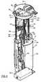
- Figure 2 is a perspective view of an embodiment of modular fuel delivery system;
- Figure 3 is a cross-sectional view of a high pressure fuel hose used in the modular fuel system of Figure 2; and
- Figure 4 is a perspective view of the hose of Figure 3 in a burst condition.
- Referring to Figure 1, a fuel system 10 for use with an internal combustion engine includes a tank mounted, modular
fuel pump assembly 12, a fuel delivery system which, in the embodiment illustrated, includes a fuel rail ormanifold 14 to whichseveral fuel injectors 16 are operably attached, and afuel conduit 18 which extends between thefuel reservoir 20 and thefuel rail 14. Depending upon the particular application of the fuel system 10, other features such as fuel filter and fuel vapour recovery canister may also be included as system components. - Referring to Figure 2, the tank mounted modular
fuel pump assembly 12 includes areservoir canister 22 having a top 24 andcylindrical body 26. A fuellevel transducer assembly 28 is attached to the exterior of thereservoir canister 22. An electric fuel pump (not shown) disposed withincanister 22 is operable to withdraw fuel from thereservoir 20, to pressurise the fuel to a desired operating pressure and to direct the pressurised fuel to thefuel conduit 18 for delivery to the engine. The pressurised fuel is delivered from the pump discharge to anintegral fluid connector 32 in a wall ofcanister 22. Acheck valve 30 disposed adjacent thefluid connector 32 prevents back flow of fuel from thefuel rail 14 and thefuel conduit 18 following engine and fuel system shut-down, aiding in subsequent engine start-up. - The
assembly 12 also includes acover 34 for closing a port or opening 36 in thefuel reservoir 20 having an exposed orexterior surface 38 and an inner orinterior surface 40 facingcanister 22 and an integral dependingflange 42 about which extends aresilient sealing member 44 for sealing engagement with a corresponding flange (not shown) extending around reservoir opening 36. Thecover 34 is connected toreservoir canister 22 by a plurality of supportingstruts 46 havingcoil springs 48 disposed thereon to urge relative separation between thecover 34 and thecanister 22. A highpressure fluid connector 50 and avapour connector 52 are integral with thecover 34. On the outer surface 38 atubular stem 54 is configured to receive the end offuel conduit 18. To the inside surface of thecover 34, a secondtubular stem 56 is similarly operably attached to ahigh pressure hose 58, which extends between and fluidly connects theintegral fluid connector 32 on top ofreservoir canister 22 with thefluid connector 50 incover 34 through which pressurised fuel exits thefuel reservoir 20. - As shown in Figure 3, the
high pressure hose 58 includes a tubular body having a plurality of annular,sinusoidal convolutions 60 and a pair of integral, relatively inflexiblecylindrical end portions 62. The high pressure hose is preferably blow moulded from fuel resistant plastics material, preferably a commonly available material such as NYLON 11. Thehose 58 is looped between thecover 34 and thereservoir canister 22 to accommodate movement therebetween and theend portions 62 are connected to theconnectors cover 34 andcanister 22, respectively. - The location of
check valve 30 between the pump outlet and thehigh pressure hose 58 places the high pressure hose in the segment of the fuel system 10 which is isolated by thecheck valve 30 following engine shut down. By placing thehose 58 between thefuel delivery system 16 and thecheck valve 30, it can act as a volume accumulator for the trapped volume of fuel. This trapped fuel volume may be subject to temperature loads from such factors as engine heat rise and climatic changes. The convolute design of thehigh pressure hose 58 is well suited to accept the volumetric increases in the fuel as a result of such temperature and pressure increases, and the concomitant stress imposed on the fuel system can be managed in an efficient manner. - Referring again to Figure 3,
high pressure hose 58 includes a region of reducedwall thickness 64 which is effective in providing a pressure fuse or point of fuel line failure in those instances in which positive pressure variations in the trapped fuel volume between thecheck valve 30 and thefuel delivery apparatus 16 exceed the capability of the high pressure tube to act as a volume accumulator. In such instances, as illustrated in Figure 4, the region of reducedwall thickness 64 is subject to a predetermined amount of plastic deformation during which the material in the region is strain hardened as it is thinned by the deformation process. Upon reaching a minimum wall thickness and hardness limit, which is material sensitive, any further increase in internal pressure causes the material to rupture, as shown at 66. Close control of the wall thickness inregion 64 facilitates precise control of the burst pressure of thehose 58, being designed to be the weak link in the fuel system, rather than another system component. The location of thehose 58 with itsintegral pressure fuse 64 within thefuel reservoir 20 controls the location of any fuel leakage caused by fuel line pressurisation so as to present minimal inconvenience. - The convoluted flexible design of the
tube 58 is well suited for accumulating increases in volume of fuel trapped between thecheck valve 30 and the engine caused by the temperature loading of the static fuel following engine-fuel system shut-down.
Claims (4)
- A fuel system for an internal combustion engine including a fuel reservoir (20) including a pump assembly (22) disposed therein, fuel delivery means (14,16) in operable communication with the engine and a fuel conduit (18) extending between the fuel reservoir and the fuel delivery means; the fuel reservoir including an electric fuel pump, check valve means (30) disposed in operable communication with an outlet of the fuel pump, and an elastomeric hose (58) extending between the check valve means and the fuel conduit; the hose including a flexible body, characterised in that the hose further comprises a region (64) of reduced wall thickness operable to accommodate pressure variation in the fuel system through expansion of the flexible body and to rupture at the region of reduced wall thickness when pressure within the hose exceeds a threshold pressure level.
- A fuel system according to claim 1, including a fluid connector disposed in a wall of the fuel reservoir operable to connect the elastomeric hose to the fuel conduit, the elastomeric hose being disposed within the fuel reservoir, wherein rupture of the region of reduced wall thickness is confined to the fuel reservoir.
- A fuel system according to claim 1 or 2, wherein the flexible body of the hose is formed with a plurality of convolutions (60) enabling expansion of the tube.
- A fuel system according to claim 3, wherein the convolutions are sinusoidal.
Applications Claiming Priority (2)
| Application Number | Priority Date | Filing Date | Title |
|---|---|---|---|
| US134439 | 1993-10-12 | ||
| US08/134,439 US5329899A (en) | 1993-10-12 | 1993-10-12 | Fuel system pressure fuse |
Publications (2)
| Publication Number | Publication Date |
|---|---|
| EP0647539A1 EP0647539A1 (en) | 1995-04-12 |
| EP0647539B1 true EP0647539B1 (en) | 1997-12-03 |
Family
ID=22463404
Family Applications (1)
| Application Number | Title | Priority Date | Filing Date |
|---|---|---|---|
| EP94202699A Expired - Lifetime EP0647539B1 (en) | 1993-10-12 | 1994-09-20 | Fuel system and pressure fuse therefor |
Country Status (4)
| Country | Link |
|---|---|
| US (1) | US5329899A (en) |
| EP (1) | EP0647539B1 (en) |
| AU (1) | AU658543B1 (en) |
| DE (1) | DE69407135T2 (en) |
Families Citing this family (16)
| Publication number | Priority date | Publication date | Assignee | Title |
|---|---|---|---|---|
| DE4330855C1 (en) * | 1993-09-11 | 1994-10-13 | Technoflow Tube Systems Gmbh | Use of a plastics pipe as a crash-protected motor-vehicle fuel line |
| US5398655A (en) * | 1994-01-14 | 1995-03-21 | Walbro Corporation | Manifold referenced returnless fuel system |
| JPH08114160A (en) * | 1994-08-25 | 1996-05-07 | Nippondenso Co Ltd | Fuel supply device for internal combustion engine |
| US5524592A (en) * | 1995-06-05 | 1996-06-11 | Walbro Corporation | Anti-siphon and anti-leanout fuel valve |
| JP2001207927A (en) * | 2000-01-26 | 2001-08-03 | Mitsubishi Electric Corp | Fuel supply device |
| JP2005163738A (en) * | 2003-12-05 | 2005-06-23 | Honda Motor Co Ltd | Fuel piping |
| US7124748B2 (en) * | 2004-12-16 | 2006-10-24 | Visteon Global Technologies, Inc. | Fuel delivery assembly for dual lobe fuel tank |
| US20080006389A1 (en) * | 2006-06-27 | 2008-01-10 | Ioan Sauciuc | Preventing burst-related hazards in microelectronic cooling systems |
| US20080119123A1 (en) * | 2006-11-10 | 2008-05-22 | Ford Motor Company | Fuel filler pipe having trigger point |
| DE102008061575B4 (en) * | 2008-12-11 | 2010-11-25 | Continental Automotive Gmbh | Corrugated pipe of a fuel line |
| DE102009014072B4 (en) * | 2009-03-20 | 2014-09-25 | Continental Automotive Gmbh | Common rail injection system and method for pressure relief of a common rail injection system |
| US9879829B2 (en) * | 2010-06-15 | 2018-01-30 | Shaw Development, Llc | Tank module interface for fluid reservoirs |
| US9464609B2 (en) * | 2013-09-06 | 2016-10-11 | Ford Global Technologies, Llc | Fuel delivery system including integrated check valve |
| EP3103998A1 (en) * | 2015-06-10 | 2016-12-14 | WEMA System AS | Configurable fuel tank sensor assembly |
| DE102017219263A1 (en) * | 2017-10-26 | 2019-05-02 | Continental Automotive Gmbh | Fuel line, fitting and fuel supply system |
| USD923056S1 (en) * | 2018-02-22 | 2021-06-22 | Carter Fuel Systems Llc | Fuel pump assembly |
Family Cites Families (17)
| Publication number | Priority date | Publication date | Assignee | Title |
|---|---|---|---|---|
| CH622327A5 (en) * | 1977-04-15 | 1981-03-31 | Luwa Ag | |
| DE2750081C2 (en) * | 1977-11-09 | 1987-01-29 | SWF Auto-Electric GmbH, 7120 Bietigheim-Bissingen | Fuel feed unit |
| EP0087508B1 (en) * | 1982-02-25 | 1985-06-26 | VDO Adolf Schindling AG | Suction device |
| DE3432727A1 (en) * | 1984-05-10 | 1985-11-14 | Robert Bosch Gmbh, 7000 Stuttgart | FUEL SUPPLY PIPE |
| JPS61175262A (en) * | 1985-01-29 | 1986-08-06 | Mitsubishi Electric Corp | Fuel feeding pump |
| US4793384A (en) * | 1986-02-11 | 1988-12-27 | Titeflex Corporation | Self-damping convoluted conduit |
| US4649884A (en) * | 1986-03-05 | 1987-03-17 | Walbro Corporation | Fuel rail for internal combustion engines |
| US4893647A (en) * | 1986-11-07 | 1990-01-16 | Walbro Corporation | In-tank fuel reservoir with reservoir fuel level control |
| US4926829A (en) * | 1988-11-28 | 1990-05-22 | Walbro Corporation | Pressure-responsive fuel delivery system |
| US4974570A (en) * | 1989-05-05 | 1990-12-04 | Carter Automotive Company, Inc. | Fuel supply module |
| US5129429A (en) * | 1989-09-11 | 1992-07-14 | Dayco Products, Inc. | Flexible hose construction |
| US4945884A (en) * | 1989-10-24 | 1990-08-07 | General Motors Corporation | Modular fuel delivery system |
| US4972875A (en) * | 1989-12-26 | 1990-11-27 | General Motors Corporation | High pressure hose for modular fuel delivery system |
| US5038741A (en) * | 1990-04-13 | 1991-08-13 | Walbro Corporation | In-tank fuel module |
| US5080077A (en) * | 1990-06-01 | 1992-01-14 | General Motors Corporation | Modular fuel delivery system |
| US5052437A (en) * | 1990-12-03 | 1991-10-01 | Ford Motor Company | Vent tube assembly |
| US5070849A (en) * | 1991-02-15 | 1991-12-10 | General Motors Corporation | Modular fuel delivery system |
-
1993
- 1993-10-12 US US08/134,439 patent/US5329899A/en not_active Expired - Fee Related
-
1994
- 1994-09-20 EP EP94202699A patent/EP0647539B1/en not_active Expired - Lifetime
- 1994-09-20 DE DE69407135T patent/DE69407135T2/en not_active Expired - Fee Related
- 1994-09-26 AU AU74208/94A patent/AU658543B1/en not_active Ceased
Also Published As
| Publication number | Publication date |
|---|---|
| AU658543B1 (en) | 1995-04-13 |
| DE69407135D1 (en) | 1998-01-15 |
| EP0647539A1 (en) | 1995-04-12 |
| US5329899A (en) | 1994-07-19 |
| DE69407135T2 (en) | 1998-03-26 |
Similar Documents
| Publication | Publication Date | Title |
|---|---|---|
| EP0647539A1 (en) | Fuel system and pressure fuse therefor | |
| US4972875A (en) | High pressure hose for modular fuel delivery system | |
| EP0491522B1 (en) | Fuel filter and pressure regulator system apparatus | |
| US6182693B1 (en) | Vapor canister and fuel tank assembly | |
| US7117856B2 (en) | Fuel delivery systems | |
| EP0959241B1 (en) | Fuel feeder for vehicles | |
| US4869225A (en) | Fuel supply device for vehicles | |
| EP0754483B1 (en) | Filter | |
| US5749345A (en) | Fuel system | |
| US5749347A (en) | Fuel leakage prevention system having latch-engaged valve | |
| KR100298294B1 (en) | Fuel supply | |
| EP1399662B1 (en) | Fuel system including an apparatus and a method for fuel vapor pressure management | |
| US6382190B1 (en) | In-tank fuel filter improved to resist electrification | |
| US5967120A (en) | Returnless fuel delivery system | |
| CN103380288A (en) | Pipe connector and fuel injection system | |
| US20090013970A1 (en) | Fuel feed apparatus | |
| EP1205333B1 (en) | In-tank fuel line quick connector including tank | |
| US6553973B1 (en) | Fuel tank cover and filter assembly for fuel tank | |
| US20090235995A1 (en) | Fuel delivery module regulator valve | |
| US20080236676A1 (en) | Fuel feed apparatus | |
| US20050217733A1 (en) | Pump module having sub-tank and elastic member | |
| US7415997B2 (en) | Seal assembly for fuel fill pipes | |
| US20080107549A1 (en) | Fuel pump and filter assembly | |
| JP2022176520A (en) | Fuel supply device | |
| KR102179627B1 (en) | High-pressure fuel pump |
Legal Events
| Date | Code | Title | Description |
|---|---|---|---|
| PUAI | Public reference made under article 153(3) epc to a published international application that has entered the european phase |
Free format text: ORIGINAL CODE: 0009012 |
|
| AK | Designated contracting states |
Kind code of ref document: A1 Designated state(s): DE FR GB |
|
| 17P | Request for examination filed |
Effective date: 19951012 |
|
| 17Q | First examination report despatched |
Effective date: 19960613 |
|
| GRAG | Despatch of communication of intention to grant |
Free format text: ORIGINAL CODE: EPIDOS AGRA |
|
| GRAH | Despatch of communication of intention to grant a patent |
Free format text: ORIGINAL CODE: EPIDOS IGRA |
|
| GRAH | Despatch of communication of intention to grant a patent |
Free format text: ORIGINAL CODE: EPIDOS IGRA |
|
| GRAA | (expected) grant |
Free format text: ORIGINAL CODE: 0009210 |
|
| AK | Designated contracting states |
Kind code of ref document: B1 Designated state(s): DE FR GB |
|
| REF | Corresponds to: |
Ref document number: 69407135 Country of ref document: DE Date of ref document: 19980115 |
|
| ET | Fr: translation filed | ||
| PLBE | No opposition filed within time limit |
Free format text: ORIGINAL CODE: 0009261 |
|
| STAA | Information on the status of an ep patent application or granted ep patent |
Free format text: STATUS: NO OPPOSITION FILED WITHIN TIME LIMIT |
|
| 26N | No opposition filed | ||
| PGFP | Annual fee paid to national office [announced via postgrant information from national office to epo] |
Ref country code: GB Payment date: 19991001 Year of fee payment: 6 |
|
| PG25 | Lapsed in a contracting state [announced via postgrant information from national office to epo] |
Ref country code: GB Free format text: LAPSE BECAUSE OF NON-PAYMENT OF DUE FEES Effective date: 20000920 |
|
| GBPC | Gb: european patent ceased through non-payment of renewal fee |
Effective date: 20000920 |
|
| PGFP | Annual fee paid to national office [announced via postgrant information from national office to epo] |
Ref country code: FR Payment date: 20040916 Year of fee payment: 11 |
|
| PGFP | Annual fee paid to national office [announced via postgrant information from national office to epo] |
Ref country code: DE Payment date: 20041130 Year of fee payment: 11 |
|
| PG25 | Lapsed in a contracting state [announced via postgrant information from national office to epo] |
Ref country code: DE Free format text: LAPSE BECAUSE OF NON-PAYMENT OF DUE FEES Effective date: 20060401 |
|
| PG25 | Lapsed in a contracting state [announced via postgrant information from national office to epo] |
Ref country code: FR Free format text: LAPSE BECAUSE OF NON-PAYMENT OF DUE FEES Effective date: 20060531 |
|
| REG | Reference to a national code |
Ref country code: FR Ref legal event code: ST Effective date: 20060531 |