EP0647177B1 - Polyester backed acrylic composite molded structure and method of manufacturing thereof - Google Patents
Polyester backed acrylic composite molded structure and method of manufacturing thereof Download PDFInfo
- Publication number
- EP0647177B1 EP0647177B1 EP92920715A EP92920715A EP0647177B1 EP 0647177 B1 EP0647177 B1 EP 0647177B1 EP 92920715 A EP92920715 A EP 92920715A EP 92920715 A EP92920715 A EP 92920715A EP 0647177 B1 EP0647177 B1 EP 0647177B1
- Authority
- EP
- European Patent Office
- Prior art keywords
- polymeric
- shell
- composite structure
- cross
- recited
- Prior art date
- Legal status (The legal status is an assumption and is not a legal conclusion. Google has not performed a legal analysis and makes no representation as to the accuracy of the status listed.)
- Revoked
Links
Images


Classifications
-
- B—PERFORMING OPERATIONS; TRANSPORTING
- B29—WORKING OF PLASTICS; WORKING OF SUBSTANCES IN A PLASTIC STATE IN GENERAL
- B29C—SHAPING OR JOINING OF PLASTICS; SHAPING OF MATERIAL IN A PLASTIC STATE, NOT OTHERWISE PROVIDED FOR; AFTER-TREATMENT OF THE SHAPED PRODUCTS, e.g. REPAIRING
- B29C70/00—Shaping composites, i.e. plastics material comprising reinforcements, fillers or preformed parts, e.g. inserts
- B29C70/58—Shaping composites, i.e. plastics material comprising reinforcements, fillers or preformed parts, e.g. inserts comprising fillers only, e.g. particles, powder, beads, flakes, spheres
- B29C70/60—Shaping composites, i.e. plastics material comprising reinforcements, fillers or preformed parts, e.g. inserts comprising fillers only, e.g. particles, powder, beads, flakes, spheres comprising a combination of distinct filler types incorporated in matrix material, forming one or more layers, and with or without non-filled layers
- B29C70/603—Shaping composites, i.e. plastics material comprising reinforcements, fillers or preformed parts, e.g. inserts comprising fillers only, e.g. particles, powder, beads, flakes, spheres comprising a combination of distinct filler types incorporated in matrix material, forming one or more layers, and with or without non-filled layers and with one or more layers of pure plastics material, e.g. foam layers
-
- A—HUMAN NECESSITIES
- A47—FURNITURE; DOMESTIC ARTICLES OR APPLIANCES; COFFEE MILLS; SPICE MILLS; SUCTION CLEANERS IN GENERAL
- A47K—SANITARY EQUIPMENT NOT OTHERWISE PROVIDED FOR; TOILET ACCESSORIES
- A47K3/00—Baths; Douches; Appurtenances therefor
- A47K3/02—Baths
- A47K3/04—Built-in baths
-
- B—PERFORMING OPERATIONS; TRANSPORTING
- B29—WORKING OF PLASTICS; WORKING OF SUBSTANCES IN A PLASTIC STATE IN GENERAL
- B29C—SHAPING OR JOINING OF PLASTICS; SHAPING OF MATERIAL IN A PLASTIC STATE, NOT OTHERWISE PROVIDED FOR; AFTER-TREATMENT OF THE SHAPED PRODUCTS, e.g. REPAIRING
- B29C70/00—Shaping composites, i.e. plastics material comprising reinforcements, fillers or preformed parts, e.g. inserts
- B29C70/68—Shaping composites, i.e. plastics material comprising reinforcements, fillers or preformed parts, e.g. inserts by incorporating or moulding on preformed parts, e.g. inserts or layers, e.g. foam blocks
- B29C70/78—Moulding material on one side only of the preformed part
Definitions
- This invention relates to a polyester backed acrylic composite molded structure. More particularly, it relates to a composite structure having a polyester polymeric backing material applied during a molding process to an acrylic shell for manufacturing of lightweight durable articles such as sanitary fixtures including bathtubs, sinks, shower receptors, lavatories and the like which are lightweight, and resist damage and delamination when subjected to impact, the weight of the user and thermal shock.
- porcelain-cast iron fixtures In the development of bathroom and kitchen fixtures, as well as bathtubs, whirlpool tubs and other composite articles, the traditional porcelain-cast iron fixtures have gradually been replaced by lighter and more resilient composite structures. While porcelain-cast iron and enameled fixtures had the advantage of having a very solid feel and a high weight bearing capability, one disadvantage of those fixtures has been their susceptibility to impact damage and extreme weight which causes great difficulties in moving and installing large fixtures such as sinks, bathtubs and whirlpool tubs.
- the preferred plastic layer is an isocyanate-modified thermosetting unsaturated polyester or polyether foam which is introduced into a mold containing the shell by reaction injection molding (RIM), or by reinforced reaction injection molding (“RRIM”) processing.
- the foamed plastic is chemically bonded to the shell by the action of silane, a coupling agent which creates chemical linkages between the metallic groups or the SiOH groups in the enamel and the reinforced foamed plastic to form the laminate.
- These composite structures possess excellent physical and mechanical properties as a result of the chemical bonding of the reinforced foamed polymeric layer to the enamel steel or stainless steel shell.
- E.P. Patent No. 370,918 is directed to sanitary fixtures, it requires two shells, an inner and an outer shell between which a polyester concrete material is poured. Two shells are required in order to provide strength and integrity to the final product.
- E.P. Patent No. 399,707 discloses composite sheets comprising at least one layer of a thermoplastic polymer and at least one layer comprising a resin reinforced with an inner filler compatible with the first layer, the resin begin polymerized directly onto the thermoplastic layer.
- the composite sheets are not self-supporting and are used as panels or coverings on buildings. These disclosures do not relate to self-supporting single-shell molded articles.
- Another prior art structure includes a polymeric, cosmetic surface layer bonded directly to a foamed plastic substrate, described as a cross-linked isocyanate-modified thermosetting unsaturated polyester or polyether resin layer to provide a high impact strength, delamination-resistant structure.
- Methylmethacrylate and commercially available adhesive Thixon 416 manufactured by Whittaker Corp., West Alexandria, Ohio, which contains a blend of 65% solvents, 35% solids including polyurethane phenolic and epoxy resins, was used as a primer to cross-link and chemically bond the polymeric cosmetic layer to the isocyanate groups in the foamed plastic while plastic is cured.
- the isocyanate was provided in the foamed plastic to provide a very fast cure of the plastic layer during RIM, or RRIM molding.
- a self-supporting polymeric composite structure preferably formed in the configuration of a bathtub, and a method for manufacturing thereof.
- the self-supporting polymeric composite structure includes a polymeric shell layer, preferably made from a thermoformable acrylic polymer of polymethylmethacrylate having a finish-side and a non-finish side.
- the self-supporting polymeric composite structure also includes a molded, cross-linked thermosetting polymeric backing layer.
- the cross-linked thermosetting polymeric layer is bonded directly to essentially the entire non-finish side of the polymeric shell and includes at least one of the following components: polyester, epoxy, acrylic, or vinyl esters, alone or blended in combination, but does not contain isocyanate.
- this cross-linked thermosetting backing prior to curing includes a rigid unsaturated polyester resin, flexible unsaturated polyester resin, a curing promoter, a peroxide cross-linking promoter and a filler in a ratio from about 2:1 resin to filler to about 1:30 resin to filler.
- the filler may include calcium carbonate, aluminum trihydrate, glass spheres, sand, ceramic, mica, talc, silica, and mixtures containing one or more of these fillers.
- a fiber reinforced resin layer which may include a layer of fibers such as fiberglass, carbon, ceramic, boron, graphite, woolastonite, aromatic polyamide and mixtures thereof may be adhered to the non-finish side of the acrylic shell.
- such layers are made of chopped fiberglass in a resinous backing.
- a weight bearing reinforcing structure is adhered to the non-finish side of the shell and to the fiber reinforced resin layer.
- This weight bearing reinforcing structure may include wood, such as chip-board, particle-board, plywood and wooden planks or it may include a polymeric composite or inorganic weight bearing structures.
- the weight bearing structure is a rectangular wooden structure made from chip-board placed below the floor portion of the bathtub. Additionally, a plurality of reinforcing wooden planks are placed below the deck portion of the shell of the tub.
- the non-finish side of the shell may be bonded to the fiber reinforcing layer by a silane based coupler which is made from a silane based primer and a methylmethacrylate and solvent blend.
- the methylmethacrylate and solvent blend preferably includes methylene chloride, styrene and water
- the silane based primer composition suitably includes 3[2(vinyl benzylamino)ethylamino] propyltrimethoxy silane dissolved in a solution of toluene, butanol, 2-butoxy ethyanol and ethyl alcohol.
- the cross-linked thermosetting polymeric backing layer which is bonded to the non-finish side of the polymeric shell, surrounds the fiber reinforcing resin layer and the weight bearing reinforcing structure.
- the non-finish side of the polymeric shell is bonded directly to the cross-linked thermosetting polymeric backing layer. This is accomplished by the cross-linking of styrene, which is present in the thermosetting polymeric backing layer, with the polymethylmethacrylate polymeric shell. This eliminates the need for both the silane based coupler and the fiber reinforced resin layer.
- the most preferred embodiment of the invention does not include a weight bearing reinforcing structure, a plurality of reinforcing wooden planks positioned below the deck portion of the shell of the tub, or blind bolts and feet positioned below the floor portion of the shell of the tub.
- a polymeric composite structure preferably formed in the shape of the bathtub, may be manufactured as described below:
- a polymeric shell is formed, preferably a thermoformable acrylic shell of polymethylmethacrylate, to a suitable shape such as the configuration of a bathtub.
- the non-finish side of the polymeric shell is preferably primed with the above-described silane based coupler.
- the primed or unprimed polymeric shell is then reinforced on its non-finish side with a resinous mixture of reinforcing fibers by suitable spray-up and roll down, or by other suitable techniques.
- the shell is arranged in a mold with the non-finish side covering a weight bearing reinforcing structure, such as chip-board, placed below the weight bearing portion of the shell, for instance, the floor of the tub.
- a weight bearing reinforcing structure such as chip-board
- Other reinforcing structures such as wooden boards may be placed below the deck of the shell.
- thermosetting polymeric backing material An uncured mixture of unsaturated thermosetting polymeric backing material and cross-linking promoter, as described above, is injected into the mold at a sufficient pressure to force the backing material to coat the non-finish side of the shell and cover the fiber reinforcing material and the weight bearing reinforcing structures.
- the molded thermosetting polymeric backing material is cured at suitable temperatures and for a sufficient time to allow hardening and cross-linking of the thermosetting material and bonding of the fiber reinforcing layer to the non-finish side of the shell. After sufficient curing, the composite structure is removed from the mold for trimming.
- the polymeric shell preferably primed (or unprimed) may be arranged in the molding cavity with the non-finish side covering a fibrous reinforcement, such as fiberglass or other fibrous mat.
- a fibrous reinforcement such as fiberglass or other fibrous mat.
- an additional fiberglass mat may be placed between the weight bearing reinforcing structure, such as the chip-board, and the floor of the bathtub.
- the thermosetting polymeric material is injected into the mold, coating the non-finish side of the shell and embedding the fibrous mat and the weight bearing board to bond the fibrous reinforcement and the weight bearing materials to the non-finish side of the shell.
- the fibrous reinforcing material such as fiberglass mat may be inserted as a preformed fibrous structure made by a thermoforming process, or the spray-up of fiberglass and resin onto a suitably shaped screen.
- no fiber reinforcing layer is applied to the non-finish side of the shell.
- the polymeric material is bonded directly to the non-finish side of the shell as follows. Polyester resins, fillers and rheological agents are blended together in a drum. The mixture is distributed equally to separate amine injection and peroxide injection units where the separate mixtures are respectively combined with a promoter and catalyst. The combinations of mixtures are then combined in a mixer and injected by gravity into an inverted mold containing the polymeric shell. The thermosetting polymeric material coats the non-finish side of the shell, and bonds directly thereto.
- Another object of the invention is to provide a lightweight polyester backed acrylic composite molded structure which has a solid feel and sound of the porcelain-coated cast iron and enameled fixtures.
- a further object of the invention is to provide a composite molded structure which is resistant to damage and delamination when subjected to impact.
- Still another object of the invention is to provide an improved apparatus for forming composite molded structures.
- Still another object of the invention is to provide an improved method for manufacturing composite molded structures.
- Yet another object of the invention is to provide a polyester backed acrylic composite molded structure which can be molded under low pressures without the need for expensive hydraulic mold press which is needed for RIM or RRIM molding.
- the invention accordingly comprises the several steps and the relation of one or more of such steps with respect to each of the others, and the article possessing the features, properties, and the relation of elements, which are exemplified in the following detailed disclosure, and the scope of the invention will be indicated in the claims.
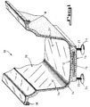
- Fig. 1 illustrates a polyester backed acrylic composite molded structure.
- the composite molded structure is in the configuration of a bathtub 10.
- Bathtub 10 includes a polymeric shell, preferably a thermoformable shell, most preferably an acrylic shell 12 having a polished finish side 20 which is normally exposed to the user.
- Acrylic shell 12 also includes a non-finish side 21 which is bonded to a molded thermosetting polymeric backing which does not contain isocyanate.
- the polymeric backing is a blended polyester backing material 14.
- a fiberglass, graphite fiber, carbon fiber, boron fiber, ceramic fiber, woolastonite fiber, aromatic polyamide fiber or similar reinforcing material may be applied using spray-up techniques prior to molding.
- the fiber reinforcing material is molded to the acrylic shell 12 by the polyester backing material 14 during the molding process.
- a floor reinforcing means 16 preferably formed of chip-board, particle-board or plywood is molded into the polyester backing 14 below the acrylic shell 12 under the floor of the bathtub 10.
- deck supporting means 18, such as wooden boards are molded under the deck area of the acrylic shell 12 within the polyester backing 14.
- blind blots 22 which are positioned after the molding process has been completed, through a portion of the molded polyester backing material 14 and into the floor reinforcing means 16.
- Feet 24 are attached to the blind bolts 22 for supporting the weight of the tub, user and water during bathing.
- FIG. 2 A schematic flow chart illustrating the preferred low pressure resin transfer molding (LPRTM) apparatus 25 suitable for carrying out a molding process is shown in Fig. 2.
- Molding apparatus 25 includes mixer 26, such as a 0,42 m 3 (110 gallon) capacity NAUTA mixer manufactured by Daymixing Corp., Cincinnati, Ohio.
- the uncured, mixed polyester and filler backing material is transferred from mixer 26 to a pressure pot liner 28 which suitably fits within a pressure pot 29, Model No. QM 5744 both of which are manufactured by Devilbiss Corp., Toledo, Ohio.
- the pressure pot 29 is closed and compressed air 30 is pumped into the pressure pot 29.
- polymer delivery hose 34 is a flexible PVC hose having 25,4 mm (one (1") inch) diameter which is disposed of and replaced following the molding process.
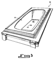
- Figs. 2 and 3 illustrate mold 36 which preferably includes molding receptacle 38, formed from cast aluminum having a cavity for receiving the acrylic shell 12, leaving a molding space between the non-finish side 21 of acrylic shell 12 and an interior face 44 of the molding receptacle 38.
- molding receptacle 38 has a relatively smooth interior race 44 for forming the shape of the polyester backing 14, and is preferably formed from a material having good heat dissipating characteristics, such as cast aluminum. It is preferred that molding receptacle 38 also include a water jacket 45 or the like to regulate desired temperature of the mold 36 (see Fig. 4).
- the uncured polyester backing and filler mixture is introduced into the molding receptacle 38 from polymer delivery hose 34 into a molding aperture 46 which is located approximately in the geometric center of a portion of the molding receptacle 38 for molding the tub floor. As shown in Fig.
- interior face 44 of molding receptacle 38 includes a rectangular indentation 48 of suitable dimension to retain tub floor reinforcement 16, preferably a rectangular piece of chip-board, or alternatively particle-board, plywood, wooden plank, fiberboard or a composite, plastic, fiberglass or other suitable weight bearing structural reinforcing material.
- the molding receptacle may suitably also include positioners or slots (not shown) for retaining deck supports 18, which preferably include wooden reinforcing 25,4 mm (1") by 25,4 mm (1") boards illustrated in Fig. 1.
- mold seals are not required, and may actually impede the flow of the uncured polyester resin and filler mix into the cavity formed between the non-finish side 21 of the acrylic shell 12 and the interior face 40 of molding receptacle 38. Due to the absence of mold seals, there is some spillover of polyester backing material 14 and adherence of the hardened backing material to portions of the molding receptacle 38 due to the molding and curing process. Accordingly, hydraulic lifters are not ordinarily utilized. Rather, after the polyester backing 14 is sufficiently cured the molded tub is loosened or cut from the molding receptacle 38 and removed by hand.
- mold 36 also includes a shell support and mold closing means 40 which maintains the shape of the thin acrylic shell 12 during the molding process.
- Shell support and mold closing means 40 also hold acrylic shell 12 in proper orientation within molding receptacle 38.
- Mold 36 may be kept closed by an suitable means, however, the low molding and curing pressures used in the invention eliminates the necessity for the use of expensive hydraulic mold presses which are typically required in RIM and RRIM molding. For example, four C clamps 42, rated at 225 kg (500 lbs). each, are entirely satisfactory for keeping mold 36 closed during the molding and curing process.
- Mold 36 as viewed in the open position is illustrated in greater detail in Fig. 4, showing molding receptacle 38, and shell support and mold closing means 40 suitably held above molding receptacle 38 by mold opening and lifting means, such as chain hoist 50.
- mold opening and lifting means such as chain hoist 50.
- other mold opening and closing means such as pivoting or levered systems, electro-mechanical or hydraulic mold clamps may be used instead of chain hoist 50 and clamps 42 during the molding process of the invention.
- shell support and mold closing means 40 is typically formed from cast aluminum core 52 which is coated with urethane skin 54.
- Shell support and mold closing means 40 conform to the shape of and supports finish side 20 of acrylic shell 12, without scratching or otherwise damaging the polished finish.
- Teflon strips 56, or other non-abrasive materials are included around the periphery of urethane skin 52 for contacting and urging a deck portion of acrylic shell 12 towards molding receptacle 38 during the molding process without causing damage to finish side 20 of the deck portion of acrylic shell 12.
- a detailed description of other suitable molding apparatus which may be adapted for use with the present invention is described in commonly assigned co-pending U.S. Patent Application Serial No. 07/467,384, allowed September 24, 1991.
- acrylic shell 12 is formed from a cell cast acrylic sheet, preferably polymethylmethacrylate, and has a highly polished finish side and a non-finish side.
- Acrylic shell 12 preferably has a thickness of approximately 3.2 millimeters.
- the acrylic sheet may be made from other materials such as those described in United States Patent Nos. 4,844,955 and 4,844,944.
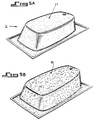
- the acrylic sheet is thermoformed using well known vacuum thermoforming apparatus into the desired shape of acrylic shell 12 which is illustrated in Fig. 5A.
- the thermoformed acrylic shell 12 may be preferably treated on non-finish side 21 with a bonding primer composition.
- a primer composition includes a silane based primer AP-134, manufactured by Lord Corp. in Erie, Pennsylvania. It contains a silane compound at a 10% concentration in a solvent of 75% toluene, 5% butanol, 5% 2-butoxy ethanol and 5% ethyl alcohol.
- a suitable silane compound is 3[2(vinyl benzylamino)ethylamino] propyltrimethoxy silane at a preferred 10% concentration, although the concentration of this silane compound may range from about 1% to about 20%, preferably from about 5% to about 15%.
- the silane primer AP-134 is most preferably mixed at a 1% concentration by weight with 1% water, 9.8% styrene, 29.4% methylene chloride and 58.8% methylmethacrylate.
- concentration of these components may range from about 0.1% to 10%, preferably from about 0.5% to about 2% silane primer such as AP-134; from about 0.1% to about 10%, preferably from about 0.5% to about 2.0% water; from about 0.1% to about 98%, preferably from about 5% to about 15%, styrene; from about 2.5% to about 98%, preferably from about 25% to about 35% methylene chloride; and from about 98% to about 5%, preferably from about 70% to about 40% methylmethacrylate.
- the primer solution promotes cross-linking and improves bonding between the polyester reinforced backing and the non-finish side 21 of the acrylic shell, thereby providing for faster demolding times.
- Other compositions useful as bonding primer solutions are described in the above-referenced U.S. Patent Nos. 4,844,955 and 4,844,944 to Graefe et al. However, if the demolding times are increased, or if sufficient bonding occurs during the spray up reinforcing step, the bonding primer is not necessary.
- the thermoformed and preferably primed acrylic shell 12 is reinforced with a resinous mixture of fibrous material, including chopped fiberglass, ceramic fibers, boron fibers, graphite or carbon fibers, woolastonite fibers, or aromatic polyamide fibers. It is preferred that the reinforcing materials include a sprayed on and rolled out mixture of chopped fiberglass from about 10% to about 40%, preferably from about 15% to about 35%, and most preferably about 30% by weight; and polyester resin from about 60% to about 90%, preferably from about 85% to about 75%, and most preferably about 70% by weight.
- the sprayed on fiberglass is typically designated as fiberglass reinforced plastic (FRP) or glass reinforced plastic (GRP).
- the polyester resin preferably includes a mixture of a rigid unsaturated polyester resin and styrene monomer designated 31-439 by the Reichhold Corp.
- the polyester resin may also include a flexible unsaturated resin designated 97-088 by Reichhold Corp. and a styrene monomer.
- the polyester resin is combined with a curing or cross-linking promoter containing from about 0.01% to about 1%, preferably from about 0.05% to about 0.5%, most preferably about 0.2% cobalt naphthanate; and from about 0.1% to about 5%, preferably from about 0.5 to about 3%, most preferably about 1% methyl ethyl ketone peroxide, percentages based on weight of resin only.
- the resin and chopped fiberglass mixture is typically applied by suitable spray equipment such as Venus Model HI SSCW 2100 manufactured by Venus-Gusmer Corp., Kent, Washington.
- suitable spray equipment such as Venus Model HI SSCW 2100 manufactured by Venus-Gusmer Corp., Kent, Washington.
- reinforced acrylic shell 58 illustrated in Fig. 5B is placed in molding receptacle 38 with reinforcing weight bearing structures 16 and 18 placed below the tub floor and deck regions, respectively.
- the acrylic shell 12 is preferably primed and reinforced with a matted or woven fibrous reinforcing material, as described above. It is preferred that the matted or woven fibrous reinforcing material is a 472.5 g/m 2 (1 & 1/2 ounce per square foot) fiberglass mat.
- the fibrous reinforcing material is placed inside the molding receptor, preferably below weight bearing floor supporting board 16, and another fiber reinforcing mat is placed above reinforcing board 16 and below floor of shell 12.
- the fiberglass or similar mat of fibrous reinforcing material is adhered to acrylic shell 12 during the molding step.
- the fibrous reinforcing material is preformed prior to the molding step and placed as a single unit inside molding receptacle 38 prior to the placement of reinforcing board 16 and acrylic shell 12 within molding receptacle 38.
- Preforming of the fiberglass reinforcing material may be obtained using thermoformable fiberglass and plastic composite or similar fibrous composite using thermoforming techniques which are well known to those skilled in the art.
- preforming may be accomplished by spray-up of a resinous mixture of chopped fiberglass or other fibers onto a shaped mesh or screen by known techniques.
- mold 36 is closed by placing the urethane coated surface 54 and TEFLON strips 56 of shell support and mold closing means 40 in suitable contact with finish-side 21 of acrylic shell 12.
- the mold is suitably clamped to provide sufficient venting by four heavy duty C clamps 42 to secure shell support and mold closing means 40 to molding receptacle 38.
- the temperature of the mold is stabilized between 311°K and 322°K (100° and 120°F) using water jacket 45 in molding receptacle 38.
- LPRTM low pressure resin transfer molding
- other low pressure injection, gravity casting or displacement molding processes may also be suitably adapted for use in the present invention.
- the preferred resin, filler and catalyst formulation is also described below.
- polyester resin and filler formulation includes the following percentages based on weight: rigid unsaturated polyester resin and styrene monomer, sold under the name Reichhold 31-439, 35.20%; flexible unsaturated polyester resin and styrene monomer sold under the name Reichhold 97-088, 11.90%; styrene monomer, 2.48%; calcium carbonate (filler), sold under the name Vicron 15-15, 49.6%; dimethylparatoluidene (DMPT)(activator/promoter), 0.6%; benzoyl peroxide, sold under the name Cadox 40 E (40% benzyl peroxide solution), 0.76%.
- DMPT dimethylparatoluidene
- the combination of materials range from about 0% to about 98%, preferably from about 25% to about 45% Reichhold 31-439; from about 98% to about 0%, preferably from about 20% to about 5% Reichhold 97-088; from about 0% to about 40%, preferably from about 1% to about 10% styrene; from about 0% to about 75%, preferably from about 40% to about 60% Vicron 15-15; from about O.05% to about 5%, preferably from about O.2% to about 1% DMPT; and from about 0.05% to about 5%, preferably from about 0.2% to about 2% Cadox 40E.
- the ratio of resin to filler may range from no filler at all, or as high as 1:30, depending upon the type of filler used and the filler particle size. Preferably the ratio of resin to filler may be from about 2:1 to about 1:3.
- Other fillers may be added in addition to or instead of calcium carbonate, including aluminum trihydrate, glass spheres, sand, ceramic, mica, talc, silica and other suitable filling materials.
- Various other fillers are described in U.S. Patent Nos. 4,844,955 and 4,844,944 to Graefe et al.
- foaming agents may be utilized to decrease the weight of the molded composite article.
- polyester blends may be used with additional fillers, foaming agents and other catalysts without departing from the scope of the present invention, as long as the resin and catalyst formulations have a sufficient time to cure to allow low pressure molding of the molded article of present invention.
- the use of isocyanate in the resin system is undesirable since such compounds speed up the curing process to such an extent as to require high pressure and high speed molding processes, such as RIM or RRIM, thereby requiring use of the expensive RRIM and RIM high pressure molding apparatus.
- thermosetting polymeric materials can include epoxy, acrylic and vinyl esters and blends thereof which do not contain isocyanate. Additional useful resin compositions suitable for the present invention are also described in the aforementioned U.S. Patent Nos. 4,844,944 and 4,844,955 to Graefe et al.
- the rigid unsaturated polyester and flexible unsaturated polyester resins are mixed in mixer 26 and the styrene monomer is then added.
- DMPT is also added and thoroughly mixed, and the filler material, such as calcium carbonate is then mixed typically for about 45 to 1 & 1/2 hours.
- Forty-five kg. (100 lbs.) of the material is then dispensed into the lined pressure pot 29.
- Approximately .337 kg. (3/4 lbs.) of benzoyl peroxide (CADOX 40E) cross-linking promoter is added and mixed for about one minute.
- the pressure pot 29 is closed and pressurized by compressed air source 30 to about .348 kg/cm 2 (5 psi).
- Throttle valve 32 is opened and the air pressure to the pressure pot 29 is increased to about .697 kg/cm 2 (10 psi).
- the air pressure is continuously increased by approximately .348 kg/cm 2 (5 psi) at one minute intervals up to a pressure of from about 1.395 kg/cm 2 (20 psi) to about 1.744 kg/cm 2 (25 psi), the pressure is maintained for about 5 to 8 minutes until the mold is filled.
- the throttle valve is closed and the clamps are tightened to seal the mold.
- the molded article is then cured.
- Curing time after the mold is filled for the above-described mixture is approximately 2 minutes to 22 minutes, preferably from about 2 minutes to about 6 minutes, but the molded structure may be maintained in the mold for longer times. If the silane based primer is not utilized, curing may range from about 45 minutes to 8 or more hours when cured overnight. The longer cure times provide a stronger bond to be formed between the polyester resin and non-finish side 21 of the acrylic shell.
- mold 36 is opened and shell support mold closing means 40 is removed. Any overflow of hardened polyester resin adhering to the outside of molding receptacle 38 is cut away and molded bathtub 10 is removed by hand from molding receptacle 38.
- Fig. 6 freshly demolded bathtub 10 is trimmed of excess polyester hardened backing material 14 using suitable equipment such as trimming table 60 and horizontally mounted circular saw 62.
- the finished polyester backed composite bathtub 10 of the first and second embodiments of the invention is shown in Figs. 7A through 7C.
- Blind bolts 22 and feet 24, illustrated in Figs. 1 and 6 are inserted on the bottom surface of the bathtub through the molded polyester backing 14 and into deck supporting board 18.
- the acrylic shell 12 may have a thickness of about 3.2 millimeters while the fiber reinforcement is typically from about 1.0 to 2.0 millimeters measured from non-finish side 21 of the shell.
- the total thickness of the molded bathtub is about 8 to 10 millimeters in the side wall region and about 20-25 millimeters on the floor region.
- the total thickness of the deck region may range from about 5 millimeters to about 35 millimeters, preferably from about 8 millimeters to about 30 millimeters.
- the thickness of the polyester molded material in the walls is typically from about 4.4 to about 7 millimeters.
- the preferred tub floor support weight bearing reinforcing structure is typically made from chip-board, particle-board, plywood or wooden plank having a preferred thickness of about 11.11 mm (7/16 inches), but may range from about 6.35 mm (1/4 inch) to about 12.7 mm (1/2 of an inch) in thickness, depending on the desired thickness of the floor of the molded article and its underlying backing.
- the preferred deck supports are typically 25.4 mm x 25.4 mm (1 inch x 1 inch) wooden boards as illustrated in Fig. 1.
- Fig. 8 illustrates a composite molded structure constructed and arranged in accordance with the present invention. It is preferred that the composite molded structure is in the configuration of bathtub 70, similar to bathtub 10 described above.
- Bathtub 70 includes a polymeric shell, preferably a thermoformable shell, and most preferably an acrylic shell 71 having polished finish side 72, which is normally exposed to the user.
- Acrylic shell 71 also includes non-finish side 73 which is directly bonded to a molded thermosetting isocyanate-free polymeric backing.
- the thermosetting polymeric backing is a blended backing material 74.
- the method and apparatus used to manufacture the embodiment of the present invention do not require or use a fiber reinforcing material molded to acrylic shell 70. Rather, the non-finish side of acrylic shell 70 has a surface as illustrated in Fig. 5A, and does not include the application of fiberglass spray-up as shown in Fig. 5B.
- the embodiment of the present invention does not include fiber reinforcing means 16, deck supporting means 18, blind bolts 22 or feet 24. Moreover, it does not require a silane coupling agent which has traditionally been used to chemically bond plastic to a shell.
- Fig. 9 is a schematic flow chart illustrating the preferred liquid injection molding apparatus 80 suitable for use in the molding process of the present invention.
- Molding apparatus 80 includes a drum 91 or the like containing a blend of primary polyester resin, filler and any desired rheological agents. The mixture is divided and evenly distributed through polymer delivery hoses 92, 93 to amine injection unit 82 and peroxide injection unit 86, respectively.
- Amine injection unit 82 and peroxide injection unit 86 include injection unit pumps which meter the proper ratio of the two mixtures to static mixer 89. Injection units 82, 86 also include hydraulic proportioners which convert compressed air to hydraulic power to drive the injection unit pumps.
- the mixture from polymer delivery hose 92 is blended with a promoter in amine injection unit 82.
- the mixture from polymer delivery hose 93 is combined with a catalyst in peroxide injection unit 86.
- Both mixtures are transported to boom assembly 81 through polymer delivery hoses 83, 87.
- Boom assembly 81 includes a mixing head and support for polymer delivery hoses 83, 87. Boom assembly 81 additionally allows static mixer 89 to be moved from one mold to the next mold during manufacturing.
- Static mixer 89 provides thorough and uniform mixing of the mixtures from amine injection unit 82 and peroxide injection unit 86 such that a chemical reaction is initiated.
- the blended mixture exits static mixer 89 through polymer delivery hose 94 to mold 98.
- mold 98 is inverted such that molding receptacle 99 is positioned below mold closing means 96 and clamps 97.
- the polymer resin mixture can be injected into mold 98 by gravity.
- the mixture is thoroughly mixed when it reaches mold 98.
- Mold 98 is filled and within 2 1/2 to 3 minutes from the initiation of the chemical reaction, the liquid resin forms a gel.
- the material is sufficiently cured to allow removal of the composite structure from the mold.
- one cycle can be completed within approximately 15 minutes in accordance with the third embodiment of the invention.
- the method used in manufacturing composite molded structures in accordance with the present invention provides several advantages over other embodiments as well as over the prior art.
- reaction time is increased, without the use of isocyanate. Accordingly, manufacturing efficiency is increased without requiring the use of expensive RRIM or RIM high pressure molding apparatus.
- the method used in accordance with the present invention eliminates the need for the use of a fiber reinforcing layer bonded to acrylic shell 70. This can be attributed to the use of amine injection unit 82 and peroxide injection unit 86 to create free radicals. The free radicals react with free sites on the polyester, thereby permitting cross-linking of the styrene during the molding process. The elimination of the fiber reinforcing material provides a product having an enhanced finished appearance. Additionally, the molded composite structure produced in accordance with the third embodiment does not require any wooden inserts.
- silane coupling agents which have previously been used to chemically bond plastic to the shell by the creation of chemical linkages are no longer necessary. Consequently, many of the disadvantages previously associated with the use of silane primers are eliminated.
- One such disadvantage has occurred where manufacturing conditions render silane primers ineffective due to the solvent or carrier drying off too quickly, thereby resulting in complete hydrolysis to silanol prior to bonding. As a result, bonding is rendered ineffective.
- molding receptacle 38 and shell support and mold closing means 40 are typically formed from cast aluminum, as discussed above.
- the present invention allows the use of a lightweight, but rigid polyester composite mold structure, such as male and female mold members formed from layers off polyester, impregnated glass, and end grained balsa sandwiched therebetween. Accordingly, the method of manufacturing a composite molded structure in accordance with the present invention reduces the need for large investments in hard tooling. Additionally, the composite molding structure is lightweight. Accordingly, the use of the hard tooling and the molding process of the method of manufacturing the acrylic composite molded structure of the third embodiment of the invention reduces manufacturing costs while increasing manufacturing efficiency.
Abstract
Description
- This invention relates to a polyester backed acrylic composite molded structure. More particularly, it relates to a composite structure having a polyester polymeric backing material applied during a molding process to an acrylic shell for manufacturing of lightweight durable articles such as sanitary fixtures including bathtubs, sinks, shower receptors, lavatories and the like which are lightweight, and resist damage and delamination when subjected to impact, the weight of the user and thermal shock.
- In the development of bathroom and kitchen fixtures, as well as bathtubs, whirlpool tubs and other composite articles, the traditional porcelain-cast iron fixtures have gradually been replaced by lighter and more resilient composite structures. While porcelain-cast iron and enameled fixtures had the advantage of having a very solid feel and a high weight bearing capability, one disadvantage of those fixtures has been their susceptibility to impact damage and extreme weight which causes great difficulties in moving and installing large fixtures such as sinks, bathtubs and whirlpool tubs.
- Initial attempts by the industry to replace these porcelain-cast iron fixtures were unsuccessful. The early composite structures had a plastic, hollow feel which would deform, crack, chip or delaminate when subjected to impact, thermal shock, or the weight of the typical bather. In addition, these composite structures would often delaminate, crack, craze or chip when subjected to impact from the outside of the structure during manufacturing, transportation and installation of the fixture.
- A successful solution to these problems is disclosed in U.S. Patent No. 4,664,982 to Genovese et al., and in U.S. Patent No. 5,049,443 to Kuszaj et al., the disclosure of both of which are incorporated by reference herein. Both disclose composite enamelled steel or stainless steel fixtures which have the look and feel of the earlier porcelain-cast iron fixtures. The structures are light, have high structural strength, and resist delamination, chipping and denting due to impact or thermal shock. The composite structures are formed from a steel or stainless steel which may be enamelled on one or both of its faces. The excellent physical and mechanical properties are imparted to these shells as a result of the chemical bonding of a plastic layer to a non-finish side of the shell. The preferred plastic layer is an isocyanate-modified thermosetting unsaturated polyester or polyether foam which is introduced into a mold containing the shell by reaction injection molding (RIM), or by reinforced reaction injection molding ("RRIM") processing. The foamed plastic is chemically bonded to the shell by the action of silane, a coupling agent which creates chemical linkages between the metallic groups or the SiOH groups in the enamel and the reinforced foamed plastic to form the laminate. These composite structures possess excellent physical and mechanical properties as a result of the chemical bonding of the reinforced foamed polymeric layer to the enamel steel or stainless steel shell. These disclosures do not relate, however, to the manufacture of a composite structure in which an acrylic layer is bonded to a polymeric or plastic molded structure.
- Two European Patents, No. 370,918 and No. 399,707, disclose molded composite structures. Although E.P. Patent No. 370,918 is directed to sanitary fixtures, it requires two shells, an inner and an outer shell between which a polyester concrete material is poured. Two shells are required in order to provide strength and integrity to the final product. E.P. Patent No. 399,707 discloses composite sheets comprising at least one layer of a thermoplastic polymer and at least one layer comprising a resin reinforced with an inner filler compatible with the first layer, the resin begin polymerized directly onto the thermoplastic layer. The composite sheets are not self-supporting and are used as panels or coverings on buildings. These disclosures do not relate to self-supporting single-shell molded articles.
- Another prior art structure includes a polymeric, cosmetic surface layer bonded directly to a foamed plastic substrate, described as a cross-linked isocyanate-modified thermosetting unsaturated polyester or polyether resin layer to provide a high impact strength, delamination-resistant structure. These structures and their processes of manufacture are disclosed in U.S. Patent Nos. 4,844,944 and 4,844,955 both to Graefe et al., the disclosures of which are incorporated by reference herein. Methylmethacrylate and commercially available adhesive Thixon 416, manufactured by Whittaker Corp., West Alexandria, Ohio, which contains a blend of 65% solvents, 35% solids including polyurethane phenolic and epoxy resins, was used as a primer to cross-link and chemically bond the polymeric cosmetic layer to the isocyanate groups in the foamed plastic while plastic is cured. The isocyanate was provided in the foamed plastic to provide a very fast cure of the plastic layer during RIM, or RRIM molding.
- However, one of the disadvantages of the reaction molding processes discussed above is that the molding processes are carried out under high pressures and require a large and expensive hydraulic press to keep the mold closed and prevent the escape of the reacting polymeric foam during the molding process. Although these molding procedures result in a very fast cure time, the equipment required, such as the hydraulic mold press is expensive, requiring a high capital investment.
- Accordingly, it is desirable to provide an improved polymeric composite molded structure and a method of producing same.
- Generally speaking, in accordance with the present invention, a self-supporting polymeric composite structure, preferably formed in the configuration of a bathtub, and a method for manufacturing thereof, is provided. The self-supporting polymeric composite structure includes a polymeric shell layer, preferably made from a thermoformable acrylic polymer of polymethylmethacrylate having a finish-side and a non-finish side.
- The self-supporting polymeric composite structure also includes a molded, cross-linked thermosetting polymeric backing layer. The cross-linked thermosetting polymeric layer is bonded directly to essentially the entire non-finish side of the polymeric shell and includes at least one of the following components: polyester, epoxy, acrylic, or vinyl esters, alone or blended in combination, but does not contain isocyanate. Preferably, this cross-linked thermosetting backing, prior to curing includes a rigid unsaturated polyester resin, flexible unsaturated polyester resin, a curing promoter, a peroxide cross-linking promoter and a filler in a ratio from about 2:1 resin to filler to about 1:30 resin to filler. The filler may include calcium carbonate, aluminum trihydrate, glass spheres, sand, ceramic, mica, talc, silica, and mixtures containing one or more of these fillers.
- A fiber reinforced resin layer which may include a layer of fibers such as fiberglass, carbon, ceramic, boron, graphite, woolastonite, aromatic polyamide and mixtures thereof may be adhered to the non-finish side of the acrylic shell. Preferably such layers are made of chopped fiberglass in a resinous backing. A weight bearing reinforcing structure is adhered to the non-finish side of the shell and to the fiber reinforced resin layer. This weight bearing reinforcing structure may include wood, such as chip-board, particle-board, plywood and wooden planks or it may include a polymeric composite or inorganic weight bearing structures. Preferably, the weight bearing structure is a rectangular wooden structure made from chip-board placed below the floor portion of the bathtub. Additionally, a plurality of reinforcing wooden planks are placed below the deck portion of the shell of the tub.
- The non-finish side of the shell may be bonded to the fiber reinforcing layer by a silane based coupler which is made from a silane based primer and a methylmethacrylate and solvent blend. The methylmethacrylate and solvent blend preferably includes methylene chloride, styrene and water, while the silane based primer composition suitably includes 3[2(vinyl benzylamino)ethylamino] propyltrimethoxy silane dissolved in a solution of toluene, butanol, 2-butoxy ethyanol and ethyl alcohol. The cross-linked thermosetting polymeric backing layer, which is bonded to the non-finish side of the polymeric shell, surrounds the fiber reinforcing resin layer and the weight bearing reinforcing structure.
- In the present invention, the non-finish side of the polymeric shell is bonded directly to the cross-linked thermosetting polymeric backing layer. This is accomplished by the cross-linking of styrene, which is present in the thermosetting polymeric backing layer, with the polymethylmethacrylate polymeric shell. This eliminates the need for both the silane based coupler and the fiber reinforced resin layer. In addition, the most preferred embodiment of the invention does not include a weight bearing reinforcing structure, a plurality of reinforcing wooden planks positioned below the deck portion of the shell of the tub, or blind bolts and feet positioned below the floor portion of the shell of the tub.
- A polymeric composite structure, preferably formed in the shape of the bathtub, may be manufactured as described below: A polymeric shell is formed, preferably a thermoformable acrylic shell of polymethylmethacrylate, to a suitable shape such as the configuration of a bathtub. The non-finish side of the polymeric shell is preferably primed with the above-described silane based coupler. The primed or unprimed polymeric shell is then reinforced on its non-finish side with a resinous mixture of reinforcing fibers by suitable spray-up and roll down, or by other suitable techniques. After the reinforced shell has sufficiently cured, the shell is arranged in a mold with the non-finish side covering a weight bearing reinforcing structure, such as chip-board, placed below the weight bearing portion of the shell, for instance, the floor of the tub. Other reinforcing structures such as wooden boards may be placed below the deck of the shell.
- An uncured mixture of unsaturated thermosetting polymeric backing material and cross-linking promoter, as described above, is injected into the mold at a sufficient pressure to force the backing material to coat the non-finish side of the shell and cover the fiber reinforcing material and the weight bearing reinforcing structures. The molded thermosetting polymeric backing material is cured at suitable temperatures and for a sufficient time to allow hardening and cross-linking of the thermosetting material and bonding of the fiber reinforcing layer to the non-finish side of the shell. After sufficient curing, the composite structure is removed from the mold for trimming.
- In addition the polymeric shell, preferably primed (or unprimed) may be arranged in the molding cavity with the non-finish side covering a fibrous reinforcement, such as fiberglass or other fibrous mat. Preferably, an additional fiberglass mat may be placed between the weight bearing reinforcing structure, such as the chip-board, and the floor of the bathtub. The thermosetting polymeric material is injected into the mold, coating the non-finish side of the shell and embedding the fibrous mat and the weight bearing board to bond the fibrous reinforcement and the weight bearing materials to the non-finish side of the shell. It is also contemplated that the fibrous reinforcing material such as fiberglass mat may be inserted as a preformed fibrous structure made by a thermoforming process, or the spray-up of fiberglass and resin onto a suitably shaped screen.
- According to the present invention, no fiber reinforcing layer is applied to the non-finish side of the shell. Rather, the polymeric material is bonded directly to the non-finish side of the shell as follows. Polyester resins, fillers and rheological agents are blended together in a drum. The mixture is distributed equally to separate amine injection and peroxide injection units where the separate mixtures are respectively combined with a promoter and catalyst. The combinations of mixtures are then combined in a mixer and injected by gravity into an inverted mold containing the polymeric shell. The thermosetting polymeric material coats the non-finish side of the shell, and bonds directly thereto.
- Accordingly, it is an object of the invention to provide an improved composite molded structure.
- Another object of the invention is to provide a lightweight polyester backed acrylic composite molded structure which has a solid feel and sound of the porcelain-coated cast iron and enameled fixtures.
- A further object of the invention is to provide a composite molded structure which is resistant to damage and delamination when subjected to impact.
- Still another object of the invention is to provide an improved apparatus for forming composite molded structures.
- Still another object of the invention is to provide an improved method for manufacturing composite molded structures.
- Yet another object of the invention is to provide a polyester backed acrylic composite molded structure which can be molded under low pressures without the need for expensive hydraulic mold press which is needed for RIM or RRIM molding.
- Still other objects and advantages of the invention will in part be obvious and will in part be apparent from the specification.
- The invention accordingly comprises the several steps and the relation of one or more of such steps with respect to each of the others, and the article possessing the features, properties, and the relation of elements, which are exemplified in the following detailed disclosure, and the scope of the invention will be indicated in the claims.
- For a fuller understanding of the invention, reference is had to the following description taken in connection with the accompanying drawings, in which:
- Fig. 1 is a schematic partial perspective cross-sectional view illustrating a polyester backed acrylic composite bathtub;
- Fig. 2 is a schematic flow chart illustrating a low pressure resin transfer molding apparatus;
- Fig. 3 is a top perspective view of the preferred molding receptacle in accordance with the present invention;
- Fig. 4 is a perspective view of the mold according to the present invention shown in the open position, illustrating the molding receptacle, shell support and mold closing means of the present invention;
- Fig. 5A shows the non-finish side of the acrylic shell of the present invention;
- Fig. 5B shows a non-finish side of an acrylic shell after the application of fiberglass spray-up reinforcement;
- Fig. 6 shows the freshly demolded polyester backed acrylic composite bathtub of the present invention positioned on a trimming table with a horizontally oriented circular saw for trimming excess polyester backing produced during the molding process, shown with blind bolts in place;
- Figs. 7A, 7B and 7C are orthogonal views of the trimmed polyester backed acrylic composite bathtub of the present invention, shown without the blind bolts in place;
- Fig. 8 is a schematic partial perspective cross-sectional view illustrating the polyester backed acrylic composite bathtub of the present invention; and
- Fig. 9 is a schematic flow chart illustrating the low pressure resin transfer molding apparatus used to carry out the molding process of the present invention.
- Fig. 1 illustrates a polyester backed acrylic composite molded structure. Preferably, the composite molded structure is in the configuration of a
bathtub 10.Bathtub 10 includes a polymeric shell, preferably a thermoformable shell, most preferably anacrylic shell 12 having apolished finish side 20 which is normally exposed to the user.Acrylic shell 12 also includes anon-finish side 21 which is bonded to a molded thermosetting polymeric backing which does not contain isocyanate. In a preferred embodiment, the polymeric backing is a blendedpolyester backing material 14. - Additionally, a fiberglass, graphite fiber, carbon fiber, boron fiber, ceramic fiber, woolastonite fiber, aromatic polyamide fiber or similar reinforcing material (not shown) may be applied using spray-up techniques prior to molding. Alternatively, the fiber reinforcing material is molded to the
acrylic shell 12 by thepolyester backing material 14 during the molding process. A floor reinforcing means 16 preferably formed of chip-board, particle-board or plywood is molded into thepolyester backing 14 below theacrylic shell 12 under the floor of thebathtub 10. Preferably, deck supporting means 18, such as wooden boards are molded under the deck area of theacrylic shell 12 within thepolyester backing 14. It is especially preferred in the first and second embodiments of the invention to includeblind blots 22, which are positioned after the molding process has been completed, through a portion of the moldedpolyester backing material 14 and into thefloor reinforcing means 16.Feet 24 are attached to theblind bolts 22 for supporting the weight of the tub, user and water during bathing. - A schematic flow chart illustrating the preferred low pressure resin transfer molding (LPRTM)
apparatus 25 suitable for carrying out a molding process is shown in Fig. 2.Molding apparatus 25 includesmixer 26, such as a 0,42 m3 (110 gallon) capacity NAUTA mixer manufactured by Daymixing Corp., Cincinnati, Ohio. The uncured, mixed polyester and filler backing material is transferred frommixer 26 to apressure pot liner 28 which suitably fits within apressure pot 29, Model No. QM 5744 both of which are manufactured by Devilbiss Corp., Toledo, Ohio. After the addition of cross-linking promoter, thepressure pot 29 is closed andcompressed air 30 is pumped into thepressure pot 29. Oncepressure pot 29 is sufficiently charged,throttle valve 32 is opened allowing the compressed air to force the uncured polyester and filler mixture throughpolymer delivery hose 34 and intomold 36. Preferablypolymer delivery hose 34 is a flexible PVC hose having 25,4 mm (one (1") inch) diameter which is disposed of and replaced following the molding process. Figs. 2 and 3 illustratemold 36 which preferably includesmolding receptacle 38, formed from cast aluminum having a cavity for receiving theacrylic shell 12, leaving a molding space between thenon-finish side 21 ofacrylic shell 12 and aninterior face 44 of themolding receptacle 38. - As illustrated in Fig. 3,
molding receptacle 38 has a relatively smoothinterior race 44 for forming the shape of thepolyester backing 14, and is preferably formed from a material having good heat dissipating characteristics, such as cast aluminum. It is preferred thatmolding receptacle 38 also include awater jacket 45 or the like to regulate desired temperature of the mold 36 (see Fig. 4). The uncured polyester backing and filler mixture is introduced into themolding receptacle 38 frompolymer delivery hose 34 into amolding aperture 46 which is located approximately in the geometric center of a portion of themolding receptacle 38 for molding the tub floor. As shown in Fig. 3,interior face 44 ofmolding receptacle 38 includes arectangular indentation 48 of suitable dimension to retaintub floor reinforcement 16, preferably a rectangular piece of chip-board, or alternatively particle-board, plywood, wooden plank, fiberboard or a composite, plastic, fiberglass or other suitable weight bearing structural reinforcing material. The molding receptacle may suitably also include positioners or slots (not shown) for retaining deck supports 18, which preferably include wooden reinforcing 25,4 mm (1") by 25,4 mm (1") boards illustrated in Fig. 1. - Due to the low pressure molding process utilized in the present invention, mold seals are not required, and may actually impede the flow of the uncured polyester resin and filler mix into the cavity formed between the
non-finish side 21 of theacrylic shell 12 and theinterior face 40 ofmolding receptacle 38. Due to the absence of mold seals, there is some spillover ofpolyester backing material 14 and adherence of the hardened backing material to portions of themolding receptacle 38 due to the molding and curing process. Accordingly, hydraulic lifters are not ordinarily utilized. Rather, after thepolyester backing 14 is sufficiently cured the molded tub is loosened or cut from themolding receptacle 38 and removed by hand. - As further illustrated in Fig. 4,
mold 36 also includes a shell support and mold closing means 40 which maintains the shape of the thinacrylic shell 12 during the molding process. Shell support and mold closing means 40 also holdacrylic shell 12 in proper orientation withinmolding receptacle 38.Mold 36 may be kept closed by an suitable means, however, the low molding and curing pressures used in the invention eliminates the necessity for the use of expensive hydraulic mold presses which are typically required in RIM and RRIM molding. For example, four C clamps 42, rated at 225 kg (500 lbs). each, are entirely satisfactory for keepingmold 36 closed during the molding and curing process. -
Mold 36 as viewed in the open position is illustrated in greater detail in Fig. 4, showingmolding receptacle 38, and shell support and mold closing means 40 suitably held abovemolding receptacle 38 by mold opening and lifting means, such as chain hoist 50. Alternatively, other mold opening and closing means such as pivoting or levered systems, electro-mechanical or hydraulic mold clamps may be used instead of chain hoist 50 and clamps 42 during the molding process of the invention. - Referring to Fig. 4, shell support and mold closing means 40 is typically formed from
cast aluminum core 52 which is coated withurethane skin 54. Shell support and mold closing means 40 conform to the shape of and supports finishside 20 ofacrylic shell 12, without scratching or otherwise damaging the polished finish. Teflon strips 56, or other non-abrasive materials are included around the periphery ofurethane skin 52 for contacting and urging a deck portion ofacrylic shell 12 towardsmolding receptacle 38 during the molding process without causing damage to finishside 20 of the deck portion ofacrylic shell 12. A detailed description of other suitable molding apparatus which may be adapted for use with the present invention is described in commonly assigned co-pending U.S. Patent Application Serial No. 07/467,384, allowed September 24, 1991. - In accordance with the process of the present invention,
acrylic shell 12 is formed from a cell cast acrylic sheet, preferably polymethylmethacrylate, and has a highly polished finish side and a non-finish side.Acrylic shell 12 preferably has a thickness of approximately 3.2 millimeters. The acrylic sheet may be made from other materials such as those described in United States Patent Nos. 4,844,955 and 4,844,944. The acrylic sheet is thermoformed using well known vacuum thermoforming apparatus into the desired shape ofacrylic shell 12 which is illustrated in Fig. 5A. - The thermoformed
acrylic shell 12 may be preferably treated onnon-finish side 21 with a bonding primer composition. One suitable primer composition includes a silane based primer AP-134, manufactured by Lord Corp. in Erie, Pennsylvania. It contains a silane compound at a 10% concentration in a solvent of 75% toluene, 5% butanol, 5% 2-butoxy ethanol and 5% ethyl alcohol. A suitable silane compound is 3[2(vinyl benzylamino)ethylamino] propyltrimethoxy silane at a preferred 10% concentration, although the concentration of this silane compound may range from about 1% to about 20%, preferably from about 5% to about 15%. The silane primer AP-134 is most preferably mixed at a 1% concentration by weight with 1% water, 9.8% styrene, 29.4% methylene chloride and 58.8% methylmethacrylate. The concentration of these components may range from about 0.1% to 10%, preferably from about 0.5% to about 2% silane primer such as AP-134; from about 0.1% to about 10%, preferably from about 0.5% to about 2.0% water; from about 0.1% to about 98%, preferably from about 5% to about 15%, styrene; from about 2.5% to about 98%, preferably from about 25% to about 35% methylene chloride; and from about 98% to about 5%, preferably from about 70% to about 40% methylmethacrylate. - The primer solution promotes cross-linking and improves bonding between the polyester reinforced backing and the
non-finish side 21 of the acrylic shell, thereby providing for faster demolding times. Other compositions useful as bonding primer solutions are described in the above-referenced U.S. Patent Nos. 4,844,955 and 4,844,944 to Graefe et al. However, if the demolding times are increased, or if sufficient bonding occurs during the spray up reinforcing step, the bonding primer is not necessary. - The thermoformed and preferably primed
acrylic shell 12 is reinforced with a resinous mixture of fibrous material, including chopped fiberglass, ceramic fibers, boron fibers, graphite or carbon fibers, woolastonite fibers, or aromatic polyamide fibers. It is preferred that the reinforcing materials include a sprayed on and rolled out mixture of chopped fiberglass from about 10% to about 40%, preferably from about 15% to about 35%, and most preferably about 30% by weight; and polyester resin from about 60% to about 90%, preferably from about 85% to about 75%, and most preferably about 70% by weight. The sprayed on fiberglass is typically designated as fiberglass reinforced plastic (FRP) or glass reinforced plastic (GRP). - The polyester resin preferably includes a mixture of a rigid unsaturated polyester resin and styrene monomer designated 31-439 by the Reichhold Corp. The polyester resin may also include a flexible unsaturated resin designated 97-088 by Reichhold Corp. and a styrene monomer. The polyester resin is combined with a curing or cross-linking promoter containing from about 0.01% to about 1%, preferably from about 0.05% to about 0.5%, most preferably about 0.2% cobalt naphthanate; and from about 0.1% to about 5%, preferably from about 0.5 to about 3%, most preferably about 1% methyl ethyl ketone peroxide, percentages based on weight of resin only. The resin and chopped fiberglass mixture is typically applied by suitable spray equipment such as Venus Model HI SSCW 2100 manufactured by Venus-Gusmer Corp., Kent, Washington. After curing for approximately one hour, reinforced
acrylic shell 58 illustrated in Fig. 5B is placed inmolding receptacle 38 with reinforcingweight bearing structures - The
acrylic shell 12 is preferably primed and reinforced with a matted or woven fibrous reinforcing material, as described above. It is preferred that the matted or woven fibrous reinforcing material is a 472.5 g/m2 (1 & 1/2 ounce per square foot) fiberglass mat. The fibrous reinforcing material is placed inside the molding receptor, preferably below weight bearingfloor supporting board 16, and another fiber reinforcing mat is placed above reinforcingboard 16 and below floor ofshell 12. The fiberglass or similar mat of fibrous reinforcing material is adhered toacrylic shell 12 during the molding step. A further alternative is that the fibrous reinforcing material is preformed prior to the molding step and placed as a single unit insidemolding receptacle 38 prior to the placement of reinforcingboard 16 andacrylic shell 12 withinmolding receptacle 38. Preforming of the fiberglass reinforcing material may be obtained using thermoformable fiberglass and plastic composite or similar fibrous composite using thermoforming techniques which are well known to those skilled in the art. Alternatively, preforming may be accomplished by spray-up of a resinous mixture of chopped fiberglass or other fibers onto a shaped mesh or screen by known techniques. - After the acrylic shell has been suitably arranged within the molding receptor,
mold 36 is closed by placing the urethane coatedsurface 54 and TEFLON strips 56 of shell support and mold closing means 40 in suitable contact with finish-side 21 ofacrylic shell 12. The mold is suitably clamped to provide sufficient venting by four heavy duty C clamps 42 to secure shell support and mold closing means 40 tomolding receptacle 38. After the mold has been secured and properly vented, the temperature of the mold is stabilized between 311°K and 322°K (100° and 120°F) usingwater jacket 45 inmolding receptacle 38. - The low pressure resin transfer molding (LPRTM) process described below, is suitable for use in the first and second embodiments of the invention. However, other low pressure injection, gravity casting or displacement molding processes may also be suitably adapted for use in the present invention. The preferred resin, filler and catalyst formulation is also described below.
- Typically, approximately 45 kg. (100 lbs.) of material is mixed in
mixer 26. The most preferred polyester resin and filler formulation includes the following percentages based on weight: rigid unsaturated polyester resin and styrene monomer, sold under the name Reichhold 31-439, 35.20%; flexible unsaturated polyester resin and styrene monomer sold under the name Reichhold 97-088, 11.90%; styrene monomer, 2.48%; calcium carbonate (filler), sold under the name Vicron 15-15, 49.6%; dimethylparatoluidene (DMPT)(activator/promoter), 0.6%; benzoyl peroxide, sold under the name Cadox 40 E (40% benzyl peroxide solution), 0.76%. It is preferred that the combination of materials range from about 0% to about 98%, preferably from about 25% to about 45% Reichhold 31-439; from about 98% to about 0%, preferably from about 20% to about 5% Reichhold 97-088; from about 0% to about 40%, preferably from about 1% to about 10% styrene; from about 0% to about 75%, preferably from about 40% to about 60% Vicron 15-15; from about O.05% to about 5%, preferably from about O.2% to about 1% DMPT;
and from about 0.05% to about 5%, preferably from about 0.2% to about 2% Cadox 40E. - The ratio of resin to filler may range from no filler at all, or as high as 1:30, depending upon the type of filler used and the filler particle size. Preferably the ratio of resin to filler may be from about 2:1 to about 1:3. Other fillers may be added in addition to or instead of calcium carbonate, including aluminum trihydrate, glass spheres, sand, ceramic, mica, talc, silica and other suitable filling materials. Various other fillers are described in U.S. Patent Nos. 4,844,955 and 4,844,944 to Graefe et al. Although the preferred polyester resin mixture is not foamed, foaming agents may be utilized to decrease the weight of the molded composite article.
- Additionally, other polyester blends may be used with additional fillers, foaming agents and other catalysts without departing from the scope of the present invention, as long as the resin and catalyst formulations have a sufficient time to cure to allow low pressure molding of the molded article of present invention. The use of isocyanate in the resin system is undesirable since such compounds speed up the curing process to such an extent as to require high pressure and high speed molding processes, such as RIM or RRIM, thereby requiring use of the expensive RRIM and RIM high pressure molding apparatus.
- Other suitable thermosetting polymeric materials can include epoxy, acrylic and vinyl esters and blends thereof which do not contain isocyanate. Additional useful resin compositions suitable for the present invention are also described in the aforementioned U.S. Patent Nos. 4,844,944 and 4,844,955 to Graefe et al.
- In preparing a polyester resin, the rigid unsaturated polyester and flexible unsaturated polyester resins are mixed in
mixer 26 and the styrene monomer is then added. DMPT is also added and thoroughly mixed, and the filler material, such as calcium carbonate is then mixed typically for about 45 to 1 & 1/2 hours. Forty-five kg. (100 lbs.) of the material is then dispensed into the linedpressure pot 29. Approximately .337 kg. (3/4 lbs.) of benzoyl peroxide (CADOX 40E) cross-linking promoter is added and mixed for about one minute. Thepressure pot 29 is closed and pressurized bycompressed air source 30 to about .348 kg/cm2 (5 psi).Throttle valve 32 is opened and the air pressure to thepressure pot 29 is increased to about .697 kg/cm2 (10 psi). The air pressure is continuously increased by approximately .348 kg/cm2 (5 psi) at one minute intervals up to a pressure of from about 1.395 kg/cm2 (20 psi) to about 1.744 kg/cm2 (25 psi), the pressure is maintained for about 5 to 8 minutes until the mold is filled. - After the mold is filled and some resin mixture spills, the throttle valve is closed and the clamps are tightened to seal the mold.
- The molded article is then cured. Curing time after the mold is filled for the above-described mixture is approximately 2 minutes to 22 minutes, preferably from about 2 minutes to about 6 minutes, but the molded structure may be maintained in the mold for longer times. If the silane based primer is not utilized, curing may range from about 45 minutes to 8 or more hours when cured overnight. The longer cure times provide a stronger bond to be formed between the polyester resin and
non-finish side 21 of the acrylic shell. After curing has been completed,mold 36 is opened and shell support mold closing means 40 is removed. Any overflow of hardened polyester resin adhering to the outside ofmolding receptacle 38 is cut away and moldedbathtub 10 is removed by hand frommolding receptacle 38. - As shown in Fig. 6, freshly
demolded bathtub 10 is trimmed of excess polyester hardenedbacking material 14 using suitable equipment such as trimming table 60 and horizontally mountedcircular saw 62. The finished polyester backedcomposite bathtub 10 of the first and second embodiments of the invention is shown in Figs. 7A through 7C.Blind bolts 22 andfeet 24, illustrated in Figs. 1 and 6 are inserted on the bottom surface of the bathtub through the moldedpolyester backing 14 and intodeck supporting board 18. - The
acrylic shell 12 may have a thickness of about 3.2 millimeters while the fiber reinforcement is typically from about 1.0 to 2.0 millimeters measured fromnon-finish side 21 of the shell. Typically the total thickness of the molded bathtub is about 8 to 10 millimeters in the side wall region and about 20-25 millimeters on the floor region. The total thickness of the deck region may range from about 5 millimeters to about 35 millimeters, preferably from about 8 millimeters to about 30 millimeters. The thickness of the polyester molded material in the walls is typically from about 4.4 to about 7 millimeters. The preferred tub floor support weight bearing reinforcing structure is typically made from chip-board, particle-board, plywood or wooden plank having a preferred thickness of about 11.11 mm (7/16 inches), but may range from about 6.35 mm (1/4 inch) to about 12.7 mm (1/2 of an inch) in thickness, depending on the desired thickness of the floor of the molded article and its underlying backing. The preferred deck supports are typically 25.4 mm x 25.4 mm (1 inch x 1 inch) wooden boards as illustrated in Fig. 1. - Reference is now made to Fig. 8 which illustrates a composite molded structure constructed and arranged in accordance with the present invention. It is preferred that the composite molded structure is in the configuration of
bathtub 70, similar tobathtub 10 described above.Bathtub 70 includes a polymeric shell, preferably a thermoformable shell, and most preferably anacrylic shell 71 havingpolished finish side 72, which is normally exposed to the user.Acrylic shell 71 also includesnon-finish side 73 which is directly bonded to a molded thermosetting isocyanate-free polymeric backing. Preferably, the thermosetting polymeric backing is a blendedbacking material 74. - In contrast to the above described methods and apparatuses, the method and apparatus used to manufacture the embodiment of the present invention do not require or use a fiber reinforcing material molded to
acrylic shell 70. Rather, the non-finish side ofacrylic shell 70 has a surface as illustrated in Fig. 5A, and does not include the application of fiberglass spray-up as shown in Fig. 5B. In addition, the embodiment of the present invention does not includefiber reinforcing means 16, deck supporting means 18,blind bolts 22 orfeet 24. Moreover, it does not require a silane coupling agent which has traditionally been used to chemically bond plastic to a shell. - Fig. 9 is a schematic flow chart illustrating the preferred liquid
injection molding apparatus 80 suitable for use in the molding process of the present invention.Molding apparatus 80 includes adrum 91 or the like containing a blend of primary polyester resin, filler and any desired rheological agents. The mixture is divided and evenly distributed throughpolymer delivery hoses amine injection unit 82 and peroxide injection unit 86, respectively. -
Amine injection unit 82 and peroxide injection unit 86 include injection unit pumps which meter the proper ratio of the two mixtures tostatic mixer 89.Injection units 82, 86 also include hydraulic proportioners which convert compressed air to hydraulic power to drive the injection unit pumps. - The mixture from
polymer delivery hose 92 is blended with a promoter inamine injection unit 82. Similarly, the mixture frompolymer delivery hose 93 is combined with a catalyst in peroxide injection unit 86. Both mixtures are transported toboom assembly 81 throughpolymer delivery hoses Boom assembly 81 includes a mixing head and support forpolymer delivery hoses Boom assembly 81 additionally allowsstatic mixer 89 to be moved from one mold to the next mold during manufacturing. - The mixtures, which are still separate, are then transported from
boom assembly 81 tostatic mixer 89 through polymer delivery hoses 84, 88, where the amine and peroxide resins contact and mix with each other for the first time.Static mixer 89 provides thorough and uniform mixing of the mixtures fromamine injection unit 82 and peroxide injection unit 86 such that a chemical reaction is initiated. - The blended mixture exits
static mixer 89 throughpolymer delivery hose 94 to mold 98. As further illustrated in Fig. 9, mold 98 is inverted such that molding receptacle 99 is positioned below mold closing means 96 and clamps 97. Thus, the polymer resin mixture can be injected into mold 98 by gravity. The mixture is thoroughly mixed when it reaches mold 98. Mold 98 is filled and within 2 1/2 to 3 minutes from the initiation of the chemical reaction, the liquid resin forms a gel. Within about 9 minutes, the material is sufficiently cured to allow removal of the composite structure from the mold. Thus, one cycle can be completed within approximately 15 minutes in accordance with the third embodiment of the invention. - After the mold is sufficiently cured, a blast of compressed air from the male side of the mold is used to release the female mold member containing the molded structure. Ejector mechanisms on the female mold member are used to separate the male and female mold members. The normal mode of operation continues until a solvent flush is necessary to remove excess material from
static mixer 89 before the mixture gels. - The method used in manufacturing composite molded structures in accordance with the present invention provides several advantages over other embodiments as well as over the prior art. First, the mixtures from
amine injection unit 82 and peroxide injection unit 86 are kept separate until enteringstatic mixer 89. This maintains the system as a liquid and prevents contamination. In addition, reaction time is increased, without the use of isocyanate. Accordingly, manufacturing efficiency is increased without requiring the use of expensive RRIM or RIM high pressure molding apparatus. - Second, the method used in accordance with the present invention eliminates the need for the use of a fiber reinforcing layer bonded to
acrylic shell 70. This can be attributed to the use ofamine injection unit 82 and peroxide injection unit 86 to create free radicals. The free radicals react with free sites on the polyester, thereby permitting cross-linking of the styrene during the molding process. The elimination of the fiber reinforcing material provides a product having an enhanced finished appearance. Additionally, the molded composite structure produced in accordance with the third embodiment does not require any wooden inserts. - Third, silane coupling agents which have previously been used to chemically bond plastic to the shell by the creation of chemical linkages are no longer necessary. Consequently, many of the disadvantages previously associated with the use of silane primers are eliminated. One such disadvantage has occurred where manufacturing conditions render silane primers ineffective due to the solvent or carrier drying off too quickly, thereby resulting in complete hydrolysis to silanol prior to bonding. As a result, bonding is rendered ineffective.
- Fourth,
molding receptacle 38 and shell support and mold closing means 40 are typically formed from cast aluminum, as discussed above. However, the present invention allows the use of a lightweight, but rigid polyester composite mold structure, such as male and female mold members formed from layers off polyester, impregnated glass, and end grained balsa sandwiched therebetween. Accordingly, the method of manufacturing a composite molded structure in accordance with the present invention reduces the need for large investments in hard tooling. Additionally, the composite molding structure is lightweight. Accordingly, the use of the hard tooling and the molding process of the method of manufacturing the acrylic composite molded structure of the third embodiment of the invention reduces manufacturing costs while increasing manufacturing efficiency. - It will thus be seen that the objects set forth above, among those made apparent from the preceding description, are efficiently attained and, since certain changes may be made in carrying out the above method and in the article set forth, it is intended that all matter contained in the above description and shown in the accompanying drawings shall be interpreted as illustrative and not in a limiting sense.
- It is also to be understood that the following claims are intended to cover all of the generic and specific features of the invention herein described and all statements of the scope of the invention which, as a matter of language, might be said to fall therebetween.
Claims (13)
- A self-supporting polymeric composite sanitary fixture, comprising:a single polymeric shell layer (71) having a finish-side (72) and a non-finish side (73); anda single cross-linked thermosetting polymeric backing layer (74) which is simultaneously molded to conform to the shape of and bonded directly to essentially the entire non-finish side (73) of said polymeric shell layer (71), said thermosetting polymeric backing layer (74) including at least one component selected from the group consisting of polyester, epoxy, acrylic, vinyl esters and blends thereof, said cross-linked thermosetting polymeric backing layer (74) having sufficient structural strength, eliminating the need for additional reinforcing layers.
- The polymeric composite structure as recited in claim 1, wherein said cross-linked thermosetting polymeric backing layer (74) is bonded directly to said polymeric shell layer (71) without the use of a coupling agent.
- The polymeric composite structure as recited in claim 1, wherein said polymeric shell layer (71) is an acrylic polymer of polymethylmethacrylate.
- The polymeric composite structure as recited in claim 1, wherein said cross-linked thermosetting backing layer (74), prior to curing comprises a rigid unsaturated polyester resin, a flexible unsaturated polyester resin, a curing promoter, a peroxide cross-linking promoter and a filler in a ratio of from about 2:1 resin to filler, up to about a ratio of about 1:30 resin to filler.
- The polymeric composite structure as recited in claim 4, wherein said filler is selected from the group consisting of calcium carbonate, aluminum trihydrate, glass spheres, sand, ceramic, mica, talc, silica, and mixtures thereof.
- The polymeric composite structure as recited in claim 1, having the configuration of a bathtub (70).
- A method for manufacturing a self-supporting polymeric composite structure, comprising:forming a polymeric shell (71) having a finish-side (72) and non-finish side (73) to a suitable shape;arranging said polymeric shell (71) in a mold (98);blending a polyester resin, filler and rheological agents to form a first mixture, dividing said mixture into first and second equal parts, blending said first part with a promoter and blending said second part with a catalyst, blending together said first part and said second part to form an uncured blended second mixture of unsaturated themosetting polymeric backing material and cross-linking promotor;introducing said uncured blended second mixture of unsaturated thermosetting polymeric backing material and cross-linking promoter into said mold (98) to force said backing material to directly coat the non-finish side (73) of said shell (71); andcuring said molded thermosetting polymeric backing material at a suitable temperature and sufficient time to allow hardening and cross-linking of the thermosetting polymeric material and bonding directly to said non-finish side of the polymeric shell in order to permit demolding of the composite structure without damage.
- The method for manufacturing a polymeric composite structure as recited in claim 7, wherein said thermosetting polymeric backing material includes a mixture of rigid unsaturated polyester resin, flexible unsaturated polyester resin, curing promoter, a peroxide cross-linking promoter and a filler in a ratio from about 2:1 resin to filler up to about 1:30 resin to filler.
- The method for manufacturing a polymeric composite structure as recited in claim 8, wherein said filler is selected from the group consisting of calcium carbonate, aluminum trihydrate, glass spheres, ceramic, mica, talc, silica, sand, and mixtures thereof.
- The method for manufacturing a polymeric composite structure as recited in claim 8, wherein said thermosetting polymeric resin material further includes a foaming agent for reducing the density of said backing material.
- The method for manufacturing a polymeric composite structure as recited in claim 7, wherein said thermosetting polymeric backing material includes at least one component selected from the group consisting of polyester, epoxy, acrylic, vinyl esters and blends thereof.
- The method for manufacturing a polymeric composite structure as recited in claim 7, wherein said cross-linking of said thermosetting polymeric material for bonding directly to said non-finish side (73) of said polymeric shell (71) does not include a coupling agent.
- The method for manufacturing a polymeric composite structure as recited in claim 7, wherein said composite structure has a configuration of a bathtub (70).
Applications Claiming Priority (3)
| Application Number | Priority Date | Filing Date | Title |
|---|---|---|---|
| US88194392A | 1992-05-12 | 1992-05-12 | |
| PCT/US1992/007748 WO1993023236A1 (en) | 1992-05-12 | 1992-09-10 | Polyester backed acrylic composite molded structure and method of manufacturing thereof |
| US881943 | 2001-06-15 |
Publications (2)
| Publication Number | Publication Date |
|---|---|
| EP0647177A1 EP0647177A1 (en) | 1995-04-12 |
| EP0647177B1 true EP0647177B1 (en) | 1997-11-05 |
Family
ID=25379534
Family Applications (1)
| Application Number | Title | Priority Date | Filing Date |
|---|---|---|---|
| EP92920715A Revoked EP0647177B1 (en) | 1992-05-12 | 1992-09-10 | Polyester backed acrylic composite molded structure and method of manufacturing thereof |
Country Status (10)
| Country | Link |
|---|---|
| EP (1) | EP0647177B1 (en) |
| JP (1) | JP3283261B2 (en) |
| KR (1) | KR100246937B1 (en) |
| AT (1) | ATE159889T1 (en) |
| AU (1) | AU2692092A (en) |
| BR (1) | BR9207129A (en) |
| CA (1) | CA2118499C (en) |
| DE (1) | DE69223066T2 (en) |
| ES (1) | ES2110524T3 (en) |
| WO (1) | WO1993023236A1 (en) |
Families Citing this family (20)
| Publication number | Priority date | Publication date | Assignee | Title |
|---|---|---|---|---|
| GB2291344B (en) * | 1994-07-15 | 1998-11-11 | Ram Bathrooms Plc | A bath |
| AUPN516795A0 (en) | 1995-09-01 | 1995-09-28 | Armacel Pty Limited | Layered structural article |
| DE19726502C1 (en) * | 1997-06-23 | 1998-07-30 | Peter Silbernagel | Imitation stone slabs comprising polyurethane foam filled with natural or synthetic powdered stone |
| EP0965611A1 (en) * | 1998-06-19 | 1999-12-22 | Schwanekamp GmbH | Polyurethane moulded parts, process for their preparation as well as panel shaped semi-finished product and tub-shaped objects obtainable using the polyurethane moulded parts produced in this way |
| AT4161U1 (en) * | 1999-11-05 | 2001-03-26 | Hubert Schmalnauer | TUB |
| DE10045792C5 (en) * | 2000-09-15 | 2006-02-16 | Franz Kaldewei Gmbh & Co. Kg | Method for producing a sanitary tub |
| US6625825B1 (en) * | 2000-10-04 | 2003-09-30 | Gfm, Inc. | Convertible shower |
| MXPA05007796A (en) * | 2003-01-24 | 2006-01-31 | Vec Technology Inc | Composite molded article and method of making a composite molded article. |
| DE10350458B4 (en) * | 2003-10-29 | 2005-12-22 | Stephan Wedi | Method and kit for the production of tiled sanitary facilities, such as bath or shower basins |
| KR100803387B1 (en) | 2006-11-14 | 2008-02-13 | 김용범 | Bathtub and method of manufacturing the same |
| US9596961B2 (en) * | 2010-11-15 | 2017-03-21 | Delta Faucet Company | Use of rigid polyurethane foam to encapsulate plumbing in a therapy bath |
| KR20120088496A (en) * | 2011-01-31 | 2012-08-08 | 이와오 히시다 | Casing for electronic device, method for manufacturing same, and electronic device |
| US10239289B2 (en) | 2013-04-12 | 2019-03-26 | Hexcel Corporation | Multi-component composite structures |
| US9359060B2 (en) * | 2013-11-07 | 2016-06-07 | The Boeing Company | Laminated composite radius filler with geometric shaped filler element and method of forming the same |
| CN105829046B (en) * | 2014-01-17 | 2018-05-04 | 东丽株式会社 | Coated fiber-reinforced resin products formed and its manufacture method |
| DE102016116845A1 (en) | 2016-09-08 | 2018-03-08 | Altura Leiden Holding B.V. | Plate with a reinforcement and a support |
| RU2651859C1 (en) * | 2017-01-24 | 2018-04-24 | Вадим Евгеньевич Казанцев | Manufacturing method of bath |
| ES2849477A1 (en) * | 2019-01-18 | 2021-08-18 | Diseno Y Transf De Poliester Sl | Aquatic recreational device |
| EP3892599A1 (en) * | 2020-04-06 | 2021-10-13 | Duravit Aktiengesellschaft | Sanitary article |
| GB2598902B (en) * | 2020-09-16 | 2022-12-07 | Ellsi Ltd | A sink |
Family Cites Families (5)
| Publication number | Priority date | Publication date | Assignee | Title |
|---|---|---|---|---|
| US3582388A (en) * | 1968-06-24 | 1971-06-01 | Federal Huber Co | Rigidfied synthetic resin article and method for making same |
| US3720540A (en) * | 1970-07-14 | 1973-03-13 | R Wimmer | Production of glass fiber-reinforced plastic articles |
| US3707434A (en) * | 1970-11-30 | 1972-12-26 | Federal Huber Co | Rigidified resinous laminate |
| FR2639580B1 (en) * | 1988-11-25 | 1991-05-10 | Gigon Michel | PROCESS FOR PRODUCING ARTICLES BY CASTING POLYESTER CONCRETE BETWEEN TWO SHELLS, ONE OF WHICH IS OBTAINED BY THERMOFORMING |
| IT1229708B (en) * | 1989-05-12 | 1991-09-07 | Vedril Spa | COMPOSITE SLABS. |
-
1992
- 1992-09-10 BR BR9207129A patent/BR9207129A/en not_active IP Right Cessation
- 1992-09-10 ES ES92920715T patent/ES2110524T3/en not_active Expired - Lifetime
- 1992-09-10 AT AT92920715T patent/ATE159889T1/en not_active IP Right Cessation
- 1992-09-10 DE DE69223066T patent/DE69223066T2/en not_active Expired - Fee Related
- 1992-09-10 CA CA002118499A patent/CA2118499C/en not_active Expired - Fee Related
- 1992-09-10 WO PCT/US1992/007748 patent/WO1993023236A1/en not_active Application Discontinuation
- 1992-09-10 EP EP92920715A patent/EP0647177B1/en not_active Revoked
- 1992-09-10 KR KR1019940704057A patent/KR100246937B1/en not_active IP Right Cessation
- 1992-09-10 AU AU26920/92A patent/AU2692092A/en not_active Abandoned
- 1992-09-10 JP JP52016593A patent/JP3283261B2/en not_active Expired - Fee Related
Also Published As
| Publication number | Publication date |
|---|---|
| JP3283261B2 (en) | 2002-05-20 |
| ES2110524T3 (en) | 1998-02-16 |
| KR100246937B1 (en) | 2000-03-15 |
| EP0647177A1 (en) | 1995-04-12 |
| JPH07506546A (en) | 1995-07-20 |
| AU2692092A (en) | 1993-12-13 |
| WO1993023236A1 (en) | 1993-11-25 |
| DE69223066D1 (en) | 1997-12-11 |
| ATE159889T1 (en) | 1997-11-15 |
| DE69223066T2 (en) | 1998-06-10 |
| KR950701570A (en) | 1995-04-28 |
| CA2118499A1 (en) | 1993-11-25 |
| CA2118499C (en) | 1997-01-14 |
| BR9207129A (en) | 1996-11-19 |
Similar Documents
| Publication | Publication Date | Title |
|---|---|---|
| US5601680A (en) | Polyester backed acrylic composite molded structure and method of manufacturing thereof | |
| EP0647177B1 (en) | Polyester backed acrylic composite molded structure and method of manufacturing thereof | |
| US3816234A (en) | Impact absorbing laminate and articles fabricated therefrom | |
| US4664982A (en) | Multi-layer composite structure | |
| US4158585A (en) | Washbasin liner method and article | |
| AU621884B2 (en) | Foam composite and method of forming same | |
| CA2078782C (en) | Polyester backed acrylic composite molded structure | |
| EP0489739B1 (en) | Steel multi-layered composite molded structure | |
| US5885503A (en) | Mold process for producing a finished solid surface countertop | |
| US20060208395A1 (en) | Composite material and mold process for injected molded vanity or countertop | |
| US3673617A (en) | Integral tops and bowls for sinks and the like and methods of making the same | |
| US4209862A (en) | Bathroom fixtures and process of manufacture | |
| GB2264083A (en) | Composite foam-filled articles | |
| JP2962522B2 (en) | Extended deck insert and casting method | |
| WO1999000235A1 (en) | In mold bonded composites and a method for manufacturing the composites | |
| CN1039295C (en) | Polyester backed acrylic composite molded structure | |
| WO1999018150A1 (en) | In mold bonded thin composites and a method for manufacturing the composites | |
| US3351507A (en) | Method of preparing laminate with grain surface | |
| US20230340214A1 (en) | Sanitary article and method for producing such an article | |
| KR910008869B1 (en) | Multi-layer composite structure | |
| CA1132448A (en) | Bathroom fixtures and process of manufacture | |
| Rajamanickam et al. | FRP mold and panel manufacturing for FSAE body panel and driver seat | |
| JPS6210086Y2 (en) | ||
| WO1992006834A1 (en) | Air ejection system | |
| WO1990012172A1 (en) | Decorative panels |
Legal Events
| Date | Code | Title | Description |
|---|---|---|---|
| PUAI | Public reference made under article 153(3) epc to a published international application that has entered the european phase |
Free format text: ORIGINAL CODE: 0009012 |
|
| 17P | Request for examination filed |
Effective date: 19941209 |
|
| AK | Designated contracting states |
Kind code of ref document: A1 Designated state(s): AT BE CH DE DK ES FR GB GR IE IT LI LU MC NL SE |
|
| 17Q | First examination report despatched |
Effective date: 19950901 |
|
| GRAG | Despatch of communication of intention to grant |
Free format text: ORIGINAL CODE: EPIDOS AGRA |
|
| GRAH | Despatch of communication of intention to grant a patent |
Free format text: ORIGINAL CODE: EPIDOS IGRA |
|
| GRAH | Despatch of communication of intention to grant a patent |
Free format text: ORIGINAL CODE: EPIDOS IGRA |
|
| GRAA | (expected) grant |
Free format text: ORIGINAL CODE: 0009210 |
|
| AK | Designated contracting states |
Kind code of ref document: B1 Designated state(s): AT BE CH DE DK ES FR GB GR IE IT LI LU MC NL SE |
|
| PG25 | Lapsed in a contracting state [announced via postgrant information from national office to epo] |
Ref country code: NL Free format text: LAPSE BECAUSE OF FAILURE TO SUBMIT A TRANSLATION OF THE DESCRIPTION OR TO PAY THE FEE WITHIN THE PRESCRIBED TIME-LIMIT Effective date: 19971105 Ref country code: LI Free format text: LAPSE BECAUSE OF FAILURE TO SUBMIT A TRANSLATION OF THE DESCRIPTION OR TO PAY THE FEE WITHIN THE PRESCRIBED TIME-LIMIT Effective date: 19971105 Ref country code: GR Free format text: LAPSE BECAUSE OF FAILURE TO SUBMIT A TRANSLATION OF THE DESCRIPTION OR TO PAY THE FEE WITHIN THE PRESCRIBED TIME-LIMIT Effective date: 19971105 Ref country code: DK Free format text: LAPSE BECAUSE OF NON-PAYMENT OF DUE FEES Effective date: 19971105 Ref country code: CH Free format text: LAPSE BECAUSE OF FAILURE TO SUBMIT A TRANSLATION OF THE DESCRIPTION OR TO PAY THE FEE WITHIN THE PRESCRIBED TIME-LIMIT Effective date: 19971105 Ref country code: AT Free format text: LAPSE BECAUSE OF FAILURE TO SUBMIT A TRANSLATION OF THE DESCRIPTION OR TO PAY THE FEE WITHIN THE PRESCRIBED TIME-LIMIT Effective date: 19971105 |
|
| REF | Corresponds to: |
Ref document number: 159889 Country of ref document: AT Date of ref document: 19971115 Kind code of ref document: T |
|
| ITF | It: translation for a ep patent filed |
Owner name: ING. C. CORRADINI & C. S.R.L. |
|
| REG | Reference to a national code |
Ref country code: CH Ref legal event code: EP |
|
| REF | Corresponds to: |
Ref document number: 69223066 Country of ref document: DE Date of ref document: 19971211 |
|
| PG25 | Lapsed in a contracting state [announced via postgrant information from national office to epo] |
Ref country code: SE Free format text: LAPSE BECAUSE OF FAILURE TO SUBMIT A TRANSLATION OF THE DESCRIPTION OR TO PAY THE FEE WITHIN THE PRESCRIBED TIME-LIMIT Effective date: 19980205 |
|
| ET | Fr: translation filed | ||
| REG | Reference to a national code |
Ref country code: ES Ref legal event code: FG2A Ref document number: 2110524 Country of ref document: ES Kind code of ref document: T3 |
|
| REG | Reference to a national code |
Ref country code: IE Ref legal event code: FG4D Free format text: 77285 |
|
| NLV1 | Nl: lapsed or annulled due to failure to fulfill the requirements of art. 29p and 29m of the patents act | ||
| REG | Reference to a national code |
Ref country code: CH Ref legal event code: PL |
|
| PLAV | Examination of admissibility of opposition |
Free format text: ORIGINAL CODE: EPIDOS OPEX |
|
| PLBQ | Unpublished change to opponent data |
Free format text: ORIGINAL CODE: EPIDOS OPPO |
|
| PLBI | Opposition filed |
Free format text: ORIGINAL CODE: 0009260 |
|
| PLAV | Examination of admissibility of opposition |
Free format text: ORIGINAL CODE: EPIDOS OPEX |
|
| PG25 | Lapsed in a contracting state [announced via postgrant information from national office to epo] |
Ref country code: LU Free format text: LAPSE BECAUSE OF NON-PAYMENT OF DUE FEES Effective date: 19980910 Ref country code: IE Free format text: LAPSE BECAUSE OF NON-PAYMENT OF DUE FEES Effective date: 19980910 |
|
| PLBF | Reply of patent proprietor to notice(s) of opposition |
Free format text: ORIGINAL CODE: EPIDOS OBSO |
|
| 26 | Opposition filed |
Opponent name: UCOSAN B.V. Effective date: 19980804 |
|
| PLBF | Reply of patent proprietor to notice(s) of opposition |
Free format text: ORIGINAL CODE: EPIDOS OBSO |
|
| PLBF | Reply of patent proprietor to notice(s) of opposition |
Free format text: ORIGINAL CODE: EPIDOS OBSO |
|
| PG25 | Lapsed in a contracting state [announced via postgrant information from national office to epo] |
Ref country code: MC Free format text: LAPSE BECAUSE OF NON-PAYMENT OF DUE FEES Effective date: 19990331 |
|
| PGFP | Annual fee paid to national office [announced via postgrant information from national office to epo] |
Ref country code: FR Payment date: 19990820 Year of fee payment: 8 Ref country code: GB Payment date: 19990820 Year of fee payment: 8 Ref country code: DE Payment date: 19990820 Year of fee payment: 8 |
|
| PGFP | Annual fee paid to national office [announced via postgrant information from national office to epo] |
Ref country code: BE Payment date: 19990910 Year of fee payment: 8 |
|
| PGFP | Annual fee paid to national office [announced via postgrant information from national office to epo] |
Ref country code: ES Payment date: 19990914 Year of fee payment: 8 |
|
| RDAH | Patent revoked |
Free format text: ORIGINAL CODE: EPIDOS REVO |
|
| RDAG | Patent revoked |
Free format text: ORIGINAL CODE: 0009271 |
|
| STAA | Information on the status of an ep patent application or granted ep patent |
Free format text: STATUS: PATENT REVOKED |
|
| 27W | Patent revoked |
Effective date: 20000210 |
|
| GBPR | Gb: patent revoked under art. 102 of the ep convention designating the uk as contracting state |
Free format text: 20000210 |