EP0647170B1 - A method of and apparatus for removing debris from the floptical medium - Google Patents
A method of and apparatus for removing debris from the floptical medium Download PDFInfo
- Publication number
- EP0647170B1 EP0647170B1 EP93925178A EP93925178A EP0647170B1 EP 0647170 B1 EP0647170 B1 EP 0647170B1 EP 93925178 A EP93925178 A EP 93925178A EP 93925178 A EP93925178 A EP 93925178A EP 0647170 B1 EP0647170 B1 EP 0647170B1
- Authority
- EP
- European Patent Office
- Prior art keywords
- rotating
- floptical
- debris
- disk
- medium
- Prior art date
- Legal status (The legal status is an assumption and is not a legal conclusion. Google has not performed a legal analysis and makes no representation as to the accuracy of the status listed.)
- Expired - Lifetime
Links
- 238000000034 method Methods 0.000 title claims abstract description 29
- 239000013078 crystal Substances 0.000 claims abstract description 22
- 238000010329 laser etching Methods 0.000 claims abstract description 12
- 230000008014 freezing Effects 0.000 claims abstract description 7
- 238000007710 freezing Methods 0.000 claims abstract description 7
- 238000005507 spraying Methods 0.000 claims description 22
- 238000005530 etching Methods 0.000 claims description 5
- 239000007921 spray Substances 0.000 claims description 4
- XAGFODPZIPBFFR-UHFFFAOYSA-N aluminium Chemical compound [Al] XAGFODPZIPBFFR-UHFFFAOYSA-N 0.000 claims 1
- 229910052782 aluminium Inorganic materials 0.000 claims 1
- 238000004140 cleaning Methods 0.000 abstract description 9
- 239000002699 waste material Substances 0.000 abstract description 9
- XLYOFNOQVPJJNP-UHFFFAOYSA-N water Chemical compound O XLYOFNOQVPJJNP-UHFFFAOYSA-N 0.000 description 14
- 230000003287 optical effect Effects 0.000 description 12
- 239000008188 pellet Substances 0.000 description 9
- 239000011236 particulate material Substances 0.000 description 3
- 230000007423 decrease Effects 0.000 description 2
- 239000000463 material Substances 0.000 description 2
- 238000011022 operating instruction Methods 0.000 description 2
- 239000002245 particle Substances 0.000 description 2
- 240000001829 Catharanthus roseus Species 0.000 description 1
- 229920000297 Rayon Polymers 0.000 description 1
- 238000010420 art technique Methods 0.000 description 1
- 238000013500 data storage Methods 0.000 description 1
- 239000008367 deionised water Substances 0.000 description 1
- 229910021641 deionized water Inorganic materials 0.000 description 1
- 239000000428 dust Substances 0.000 description 1
- 239000004744 fabric Substances 0.000 description 1
- 230000004907 flux Effects 0.000 description 1
- 238000012423 maintenance Methods 0.000 description 1
- 238000004519 manufacturing process Methods 0.000 description 1
- 238000012544 monitoring process Methods 0.000 description 1
- 239000002964 rayon Substances 0.000 description 1
- 239000004065 semiconductor Substances 0.000 description 1
- 239000007787 solid Substances 0.000 description 1
- 238000003860 storage Methods 0.000 description 1
- 229920002994 synthetic fiber Polymers 0.000 description 1
- 230000000699 topical effect Effects 0.000 description 1
Images
Classifications
-
- B—PERFORMING OPERATIONS; TRANSPORTING
- B08—CLEANING
- B08B—CLEANING IN GENERAL; PREVENTION OF FOULING IN GENERAL
- B08B7/00—Cleaning by methods not provided for in a single other subclass or a single group in this subclass
-
- B—PERFORMING OPERATIONS; TRANSPORTING
- B08—CLEANING
- B08B—CLEANING IN GENERAL; PREVENTION OF FOULING IN GENERAL
- B08B15/00—Preventing escape of dirt or fumes from the area where they are produced; Collecting or removing dirt or fumes from that area
- B08B15/02—Preventing escape of dirt or fumes from the area where they are produced; Collecting or removing dirt or fumes from that area using chambers or hoods covering the area
-
- B—PERFORMING OPERATIONS; TRANSPORTING
- B24—GRINDING; POLISHING
- B24C—ABRASIVE OR RELATED BLASTING WITH PARTICULATE MATERIAL
- B24C1/00—Methods for use of abrasive blasting for producing particular effects; Use of auxiliary equipment in connection with such methods
- B24C1/003—Methods for use of abrasive blasting for producing particular effects; Use of auxiliary equipment in connection with such methods using material which dissolves or changes phase after the treatment, e.g. ice, CO2
-
- B—PERFORMING OPERATIONS; TRANSPORTING
- B24—GRINDING; POLISHING
- B24C—ABRASIVE OR RELATED BLASTING WITH PARTICULATE MATERIAL
- B24C3/00—Abrasive blasting machines or devices; Plants
- B24C3/02—Abrasive blasting machines or devices; Plants characterised by the arrangement of the component assemblies with respect to each other
-
- B—PERFORMING OPERATIONS; TRANSPORTING
- B24—GRINDING; POLISHING
- B24C—ABRASIVE OR RELATED BLASTING WITH PARTICULATE MATERIAL
- B24C3/00—Abrasive blasting machines or devices; Plants
- B24C3/18—Abrasive blasting machines or devices; Plants essentially provided with means for moving workpieces into different working positions
- B24C3/20—Abrasive blasting machines or devices; Plants essentially provided with means for moving workpieces into different working positions the work being supported by turntables
- B24C3/22—Apparatus using nozzles
Definitions
- This invention relates to a method of cleaning floptical media, and in particular to removing microscopic debris from the floptical media surface and grooves after laser etching.
- US-A-4 869 090 discloses an apparatus for forming unevenness over a surface of a base plate for a magnetic disc, said apparatus comprising rotating means, a chuck on which is mounted said magnetic disc for rotating said disc at a predetermined angular velocity, a sprayer adjustably disposed over the surface of said disc for spraying a low-temperature gas containing ice-crystals onto said surface, sprayer angle adjustment means connected to said sprayer for varying an angle of said sprayer in a predetermined path at a predetermined speed over said rotating disc, said rotating surface of said disc being sprayed by said gas for a predetermined number of repetitions. Further, the document describes a method of using said apparatus.
- optical servo pattern is pre-recorded on a magnetic floppy disk.
- the optical servo pattern typically consists of a large number of equally spaced concentric tracks about the rotational axis of the disk. Data is stored in the magnetic "tracks" between the optical servo tracks using conventional magnetic recording techniques.
- An optical servo mechanism is provided to guide the magnetic read/write head accurately over the data between the optical servo tracks.
- the optical servo pattern typically consists of a large number of equally spaced concentric tracks about the rotational axis of the disk.
- each track may be a single continuous groove (Fig. 3), a plurality of equally spaced circular pits (Fig. 8), or a plurality of short equally spaced grooves or stitches (Fig. 9).
- Fig. 3 a single continuous groove
- Fig. 8 a plurality of equally spaced circular pits
- Fig. 9 a plurality of short equally spaced grooves or stitches
- Fig. 9 Various methods and systems exist for inscribing the optical servo tracks on the magnetic medium.
- U.S. Patent No. 4,961,123 entitled “Magnetic Information Media Storage With Optical Servo Tracks,” discloses a method of an apparatus etching the servo track pattern on a disk using a laser.
- etching debris is in the order of micron or sub-micron. These fine etching debris remain on the floptical media surface as well as in the etched grooves after laser etching is completed. If the floptical medium is not cleaned, these debris damage both the floptical media and the read/write heads of the floptical drive.
- Sno-GunTM Va-Tran Systems, Inc. Chula Vista, CA
- Sno-GunTM sprays CO 2 pellets onto a medium, Sno-GunTM Cleaner, Description and Operating Instructions , Va-Tran Systems, Inc. While the nozzle of a Sno-Gun travels in a certain direction to remove the undesired materials from the medium, the medium remains stationary.
- Sno-GunTM was applied to a floptical medium as directed in the operating instructions, the removal of the microscopic debris was not complete.
- the low temperature freezes the surface of a floptical medium. This happens especially when the same area is repetitively sprayed with CO 2 pellets.
- the effectiveness of Sno-GunTM diminishes as more CO 2 pellets are applied.
- the object of the current invention is to improve the removal of the microscopic and sub-microscopic debris from a floptical medium.
- Another object of the current invention is to prevent the floptical medium from being frozen during cleaning so that the microscopic debris removal remains effective.
- Yet another objective is to improve the microscopic debris removal by creating a larger energy disparity between the debris and the disk.
- the apparatus for removing debris from a floptical medium after laser etching comprises a rotating means, a chuck on which is mounted the floptical medium for rotating the floptical medium and a sprayer for spraying a low-temperature gas containing ice crystals onto the rotating floptical medium at a predetermined angle.
- the ice crystals collide with the debris, and the debris depart from the floptical medium due to a change in momentum created by the collision. Freezing of the floptical medium surface due to the ice crystals is prevented by thermal energy transfer from the chuck.
- the apparatus according to the invention is defined in claims 3 and 4, respectively.
- an external heat source is applied to the chuck.
- a low-pressure vacuum is also applied near the rotating floptical medium to further transport the debris that departed from the disk surface.
- the method of removing debris from a floptical medium after laser etching comprises the steps of:
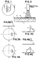
- Figure 1 is a top view of a floptical disk 1.
- the concentric optical servo tracks were etched on the disk surface between B-B'.
- C is a pair of bores on the floptical disk 1 to engage pins to lock the disk 1 for rotation.
- FIG 2 is a cross sectional view taken at A-A' of Figure 1.
- Figure 2 schematically shows the method of removing submicroscopic debris from the floptical medium.
- the floptical disk 1 is placed on the chuck 2 for rotation.
- the laser etched side of the disk is disposed distally to the chuck 2.
- the nozzle 3 of Sno-GunTM is aimed at the laser etched surface of the disk 1 for spraying CO 2 pellets or a jet stream of ice crystals 4.
- the aforementioned Sno GunTM is an example of a nozzle suitable for use.
- the nozzle 3 travels in the horizontal direction as indicated by the arrow 8 from the inner to outer radius of the floptical disk 1.
- the area 6 is being cleaned, and the area 7 is yet to be cleaned. Throughout the areas, the microscopic or submicroscopic particulate waste materials 10 are shown as black dots.
- the area 5 has been already cleaned by the method of the current invention.
- the area 5 has substantially less particulate waste materials 10 than the area 6 or 7 since the areas 6 and 7 have not yet been cleaned.
- the stitch 9 has high concentration of particulate materials 10.
- Each of these particulate waste materials 10 are in the order of microns or less than a micron.
- the ice crystals colliding with the debris on the surface of the disk 1 cause the debris to disassociate from the etched surface or stitches. It is believed that the energy transfer between the ice crystals and the debris causes cleaning as suggested by Witlock in Dry Surface Cleaning with CO 2 Snow , Compressed Air Magazine, August, 1986. Assuming that the disk is stationary, numerous small particles of solid CO 2 moving at high velocity hit the particulate materials 10. Upon collisions, the impact of the CO 2 pellets transfers sufficient momentum to the particulate waste materials 10 to overcome the particle adhesion force. As a result, the waste materials disassociate from the floptical surface. Once the particulate materials are free from the disk surface, they are transported by the flow of air generated by the jet stream of CO 2 .
- the floptical disk is rotated during the debris removal in the current invention.
- the energy transfer between the debris 10 and the disk 1 is in either direction.
- the nozzle 3 is placed so that the direction of the jet stream is against rotation of the disk as shown in Figures 3A-3C.
- Fig. 3A is a top view of the disk 1 in relation to the nozzle 3.
- Fig. 3B is a cross sectional view of the top half of Fig. 3A taken at Y-Y'. Because the nozzle 3 is angled, Figure 3B shows only a distal portion of the nozzle 3.
- the nozzle 3 is perpendicular to the surface of the disk 1.
- Figure 3C is another cross sectional view taken at X-X' of Figure 3A.
- the nozzle 3 is angled at 85° from the disk surface in such a way that the direction of the jet stream from the nozzle 3 as shown by an arrow is against the rotational direction.
- the ice crystals in the CO 2 jet stream collide substantially head-on with the debris or particulate waste materials 10 on the surface of the disk 1.
- the energy level of the debris decreases due to collision with the CO 2 pellets, assuming that the momentum of the ice crystals is larger than that of debris.
- the debris are decelerated and some energy is dissipated as heat due to collision. This momentum change causes a greater energy difference between the decelerated debris and the rotating disk and the debris to readily depart from the disk.
- the disk cleaning with a Sno-Gun is substantially improved over the stationary disk.
- Figure 4A is a top view of the disk 1 in relation to the nozzle 3. As indicated by an arrow, the disk 1 is rotated counterclockwise.
- Figure 4B is a cross sectional view of the top half of Fig. 4A taken at Y-Y'. Because the nozzle is angled, Fig. 4B shows only a proximal portion of the nozzle 3. The nozzle 3 is perpendicular to the surface of the disk 1.
- Figure 4C is another cross sectional view taken at X-X' of Fig. 4A.
- the nozzle 3 is angled at 85° from the disk surface in such a way that the direction of the jet stream from the nozzle 3 as shown by an arrow is the same as that of rotation.
- the ice crystals in the Co 2 jet stream collide with the debris substantially in the same direction on the surface of the disk 1.
- the momentum of the debris is altered so that a greater difference in energy level between the debris and the rotating disk results. This energy difference causes the debris to more readily depart or disassociate from the disk surface than when the CO 2 pellets are applied to the stationary disk.
- an icy jet stream sprayed onto the floptical disk surface lowers the disk surface temperature.
- a single track must be repetitively sprayed with the icy jet stream to substantially remove the particulate waste materials.
- the continuing application of an icy jet stream gradually freezes the disk surface.
- no debris depart or disassociate from the disk surface As a result, Sno-GunTM decreases its effectiveness as it repetitively sprays the same track.
- the external heat application may require monitoring the disk surface temperature and accordingly adjusting the heat application.
- the current invention provides a method of and apparatus for maintaining the rotating disk above the freezing temperature during jet spraying of CO 2 pellets by providing a heat reservoir in the chuck.
- An additional external heat source is not necessary in this embodiment.
- the chuck has a substantially larger thermal mass than the disk, lowering of the disk temperature is quickly recovered by heat transfer from the chuck to the disk. The chuck, then, replenishes heat from environment, assuming that the room temperature is above freezing.
- the chuck 2 is heated with an external heater (not shown). This allows a quick replenishment of the heat reservoir in the chuck 2.
- the current invention simplifies the maintenance of the disk temperature during the microscopic debris removal.
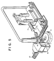
- Figure 5 shows a plan view of the apparatus for removing microscopic and submicroscopic debris from the floptical medium.
- the floptical disk 1 is placed on the chuck 2. While the disk 1 is being rotated by the chuck 2, a gas containing CO 2 pellets is sprayed onto the floptical disk surface through the nozzle 3.
- the position adjustment means 17 moves the nozzle 3 from the inside to outside radius of the rotating floptical disk 1.
- the nozzle 3 travels at a predetermined speed so that each track is sprayed with the CO 2 gas for at least a couple of times.
- the height adjustment means 12 keeps a constant distance between the nozzle 3 and the floptical disk surface 1.
- the angle adjustment means 11 sets the angle of the nozzle in a plane perpendicular to the disk surface.
- the radial angle adjustment means 16 sets an angle with respect to the radius of the disk 1. Still referring to Figure 5, the vacuum means 13 is connected to a low pressure source through the hose 14 and is located near the rotating disk 1. During the cleaning, the vacuum means 13 applies a low pressure gas through the bore 15. The debris departed from the rotating disk 1 due to CO 2 spraying are further transported towards the bore 15 by the air flow created by the vacuum.
- the distance between the nozzle 3 and the rotating disk 1 is kept at approximately 0.75".
- the direction of the nozzle 3 was held perpendicular to a plane of the radius on which the nozzle travelled and 85° from the rotating disk surface so that the direction of spraying is against that of rotation.
- the disk was rotated at 2,400 RPM, while the nozzle 3 travelled 0.3 inches per second above the disk 1 in the direction from the inner to outer radius.
Landscapes
- Engineering & Computer Science (AREA)
- Mechanical Engineering (AREA)
- Manufacturing Of Magnetic Record Carriers (AREA)
Abstract
Description
- This invention relates to a method of cleaning floptical media, and in particular to removing microscopic debris from the floptical media surface and grooves after laser etching.
- US-A-4 869 090 discloses an apparatus for forming unevenness over a surface of a base plate for a magnetic disc, said apparatus comprising rotating means, a chuck on which is mounted said magnetic disc for rotating said disc at a predetermined angular velocity, a sprayer adjustably disposed over the surface of said disc for spraying a low-temperature gas containing ice-crystals onto said surface, sprayer angle adjustment means connected to said sprayer for varying an angle of said sprayer in a predetermined path at a predetermined speed over said rotating disc, said rotating surface of said disc being sprayed by said gas for a predetermined number of repetitions. Further, the document describes a method of using said apparatus.
- Recently, floppy disk systems have been developed that combine magnetic disk recording techniques with the high track capacity servos found in optical disk systems. Such a system is described in AN INTRODUCTION TO THE INSITE 325 FLOPTICAL(R) DISK DRIVE, Godwin, which was presented at the SPIE Optical Data Storage Topical Meeting (1989). Essentially, an optical servo pattern is pre-recorded on a magnetic floppy disk. The optical servo pattern typically consists of a large number of equally spaced concentric tracks about the rotational axis of the disk. Data is stored in the magnetic "tracks" between the optical servo tracks using conventional magnetic recording techniques. An optical servo mechanism is provided to guide the magnetic read/write head accurately over the data between the optical servo tracks. By utilizing optical servo techniques, much higher track densities are available on the relatively inexpensive removable magnetic medium.
- As mentioned, the optical servo pattern typically consists of a large number of equally spaced concentric tracks about the rotational axis of the disk. As disclosed in U.S. Patent No. 4,961,123, each track may be a single continuous groove (Fig. 3), a plurality of equally spaced circular pits (Fig. 8), or a plurality of short equally spaced grooves or stitches (Fig. 9). Various methods and systems exist for inscribing the optical servo tracks on the magnetic medium. For example, U.S. Patent No. 4,961,123, entitled "Magnetic Information Media Storage With Optical Servo Tracks," discloses a method of an apparatus etching the servo track pattern on a disk using a laser.
- U.S. Applications IOM-8721 and IOM-8723 (filed June 10, 1992) show an apparatus and method for etching intermittent grooves in a floptical disk.
- During laser etching of the floptical media, particulate waste is generated. The size of etching debris is in the order of micron or sub-micron. These fine etching debris remain on the floptical media surface as well as in the etched grooves after laser etching is completed. If the floptical medium is not cleaned, these debris damage both the floptical media and the read/write heads of the floptical drive.
- Removal of laser etching debris from the floptical medium surface and grooves is a critical step in the manufacturing process. However, it is difficult to remove these microscopic or sub-microscopic debris from the floptical surface. Especially, it is harder to remove microscopic debris remaining in the stitches or grooves. In order to remove these microscopic debris, it has been attempted to wipe the etched floptical surface with synthetic cloth such as Rayon. The cloth was also used with a solution such as deionized water. However, much of the microscopic debris was not removed by this method, and the microscopic debris remained in the stitches. It has also been known in the relevant art that spraying a gas onto other recording media helps remove some undesirable materials. For example, Sno-Gun™ (Va-Tran Systems, Inc. Chula Vista, CA) has been used to remove dust from a magnetic floppy disk and flux from printed circuit boards and semiconductors. Sno-Gun™ sprays CO2 pellets onto a medium, Sno-Gun™ Cleaner, Description and Operating Instructions, Va-Tran Systems, Inc. While the nozzle of a Sno-Gun travels in a certain direction to remove the undesired materials from the medium, the medium remains stationary. When Sno-Gun™ was applied to a floptical medium as directed in the operating instructions, the removal of the microscopic debris was not complete. Moreover, during the spray cleaning, the low temperature freezes the surface of a floptical medium. This happens especially when the same area is repetitively sprayed with CO2 pellets. Thus, the effectiveness of Sno-Gun™ diminishes as more CO2 pellets are applied.
- None of these prior art techniques solved or ever addressed the above mentioned problem of removing sub-microscopic or microscopic debris from the floptical medium after laser etching. Thus, the object of the current invention is to improve the removal of the microscopic and sub-microscopic debris from a floptical medium. Another object of the current invention is to prevent the floptical medium from being frozen during cleaning so that the microscopic debris removal remains effective. Yet another objective is to improve the microscopic debris removal by creating a larger energy disparity between the debris and the disk.
- The apparatus for removing debris from a floptical medium after laser etching comprises a rotating means, a chuck on which is mounted the floptical medium for rotating the floptical medium and a sprayer for spraying a low-temperature gas containing ice crystals onto the rotating floptical medium at a predetermined angle. The ice crystals collide with the debris, and the debris depart from the floptical medium due to a change in momentum created by the collision. Freezing of the floptical medium surface due to the ice crystals is prevented by thermal energy transfer from the chuck. The apparatus according to the invention is defined in
claims - In an embodiment, an external heat source is applied to the chuck. A low-pressure vacuum is also applied near the rotating floptical medium to further transport the debris that departed from the disk surface.
- The method of removing debris from a floptical medium after laser etching comprises the steps of:
- a) mounting the medium on the chuck for rotation;
- b) rotating the medium,
- c) spraying a low-temperature gas containing ice crystals onto the rotating surface; and
- d) maintaining the disk surface temperature above
freezing. The ice crystals collide with the debris and cause
them to depart from the floptical medium. The temperature
may be maintained by applying external heat. The method
according to the invention is defined in
claims 1 and 2, respectively. -
-
- Figure 1 is a top view of the floptical disk.
- Figure 2 is a cross sectional view of the floptical disk taken at A-A' and the Sno-Gun™ nozzle.
- Figure 3 shows one embodiment where the nozzle is placed in such an angle that the direction of the jet stream is against rotation of the disk.
- Figure 4 shows another embodiment where the nozzle is placed in such an angle that the direction of the jet stream is the same as that of rotation of the disk.
- Figure 5 is a plan view of the floptical disk, the Sno-Gun, the Sno-Gun controlling device and the vacuum device.
-
- Figure 1 is a top view of a floptical disk 1. The concentric optical servo tracks were etched on the disk surface between B-B'. C is a pair of bores on the floptical disk 1 to engage pins to lock the disk 1 for rotation.
- Figure 2 is a cross sectional view taken at A-A' of Figure 1. Figure 2 schematically shows the method of removing submicroscopic debris from the floptical medium. The floptical disk 1 is placed on the
chuck 2 for rotation. The laser etched side of the disk is disposed distally to thechuck 2. While the disk 1 is rotated at approximately 2000 rpm, thenozzle 3 of Sno-Gun™ is aimed at the laser etched surface of the disk 1 for spraying CO2 pellets or a jet stream ofice crystals 4. The aforementioned Sno Gun™ is an example of a nozzle suitable for use. Thenozzle 3 travels in the horizontal direction as indicated by thearrow 8 from the inner to outer radius of the floptical disk 1. Thearea 6 is being cleaned, and thearea 7 is yet to be cleaned. Throughout the areas, the microscopic or submicroscopicparticulate waste materials 10 are shown as black dots. Thearea 5 has been already cleaned by the method of the current invention. Thearea 5 has substantially lessparticulate waste materials 10 than thearea areas particulate materials 10. Each of theseparticulate waste materials 10 are in the order of microns or less than a micron. - The ice crystals colliding with the debris on the surface of the disk 1 cause the debris to disassociate from the etched surface or stitches. It is believed that the energy transfer between the ice crystals and the debris causes cleaning as suggested by Witlock in Dry Surface Cleaning with CO2 Snow, Compressed Air Magazine, August, 1986. Assuming that the disk is stationary, numerous small particles of solid CO2 moving at high velocity hit the
particulate materials 10. Upon collisions, the impact of the CO2 pellets transfers sufficient momentum to theparticulate waste materials 10 to overcome the particle adhesion force. As a result, the waste materials disassociate from the floptical surface. Once the particulate materials are free from the disk surface, they are transported by the flow of air generated by the jet stream of CO2. - In order to improve this removal mechanism, the floptical disk is rotated during the debris removal in the current invention. Depending upon the direction of the jet stream with respect to that of rotation, the energy transfer between the
debris 10 and the disk 1 is in either direction. In one embodiment, thenozzle 3 is placed so that the direction of the jet stream is against rotation of the disk as shown in Figures 3A-3C. Fig. 3A is a top view of the disk 1 in relation to thenozzle 3. As indicated by arrows, the disk 1 is rotated counterclockwise. Fig. 3B is a cross sectional view of the top half of Fig. 3A taken at Y-Y'. Because thenozzle 3 is angled, Figure 3B shows only a distal portion of thenozzle 3. Thenozzle 3 is perpendicular to the surface of the disk 1. Figure 3C is another cross sectional view taken at X-X' of Figure 3A. Thenozzle 3 is angled at 85° from the disk surface in such a way that the direction of the jet stream from thenozzle 3 as shown by an arrow is against the rotational direction. The ice crystals in the CO2 jet stream collide substantially head-on with the debris orparticulate waste materials 10 on the surface of the disk 1. Thus, the energy level of the debris decreases due to collision with the CO2 pellets, assuming that the momentum of the ice crystals is larger than that of debris. The debris are decelerated and some energy is dissipated as heat due to collision. This momentum change causes a greater energy difference between the decelerated debris and the rotating disk and the debris to readily depart from the disk. As a result, the disk cleaning with a Sno-Gun is substantially improved over the stationary disk. - In another embodiment, the direction of the jet stream from the
nozzle 3 is the same as that of rotation as shown in Figure 4. Figure 4A is a top view of the disk 1 in relation to thenozzle 3. As indicated by an arrow, the disk 1 is rotated counterclockwise. Figure 4B is a cross sectional view of the top half of Fig. 4A taken at Y-Y'. Because the nozzle is angled, Fig. 4B shows only a proximal portion of thenozzle 3. Thenozzle 3 is perpendicular to the surface of the disk 1. Figure 4C is another cross sectional view taken at X-X' of Fig. 4A. Thenozzle 3 is angled at 85° from the disk surface in such a way that the direction of the jet stream from thenozzle 3 as shown by an arrow is the same as that of rotation. The ice crystals in the Co2 jet stream collide with the debris substantially in the same direction on the surface of the disk 1. Thus, the energy transfer is from the ice crystals to the debris, and the debris are accelerated. The momentum of the debris is altered so that a greater difference in energy level between the debris and the rotating disk results. This energy difference causes the debris to more readily depart or disassociate from the disk surface than when the CO2 pellets are applied to the stationary disk. - During the course of debris removal, an icy jet stream sprayed onto the floptical disk surface lowers the disk surface temperature. However, a single track must be repetitively sprayed with the icy jet stream to substantially remove the particulate waste materials. Thus, the continuing application of an icy jet stream gradually freezes the disk surface. When the surface is covered with ice, no debris depart or disassociate from the disk surface. As a result, Sno-Gun™ decreases its effectiveness as it repetitively sprays the same track. Although, it is possible to apply heat from an external heat source, the external heat application may require monitoring the disk surface temperature and accordingly adjusting the heat application. The current invention provides a method of and apparatus for maintaining the rotating disk above the freezing temperature during jet spraying of CO2 pellets by providing a heat reservoir in the chuck. An additional external heat source is not necessary in this embodiment. Because the chuck has a substantially larger thermal mass than the disk, lowering of the disk temperature is quickly recovered by heat transfer from the chuck to the disk. The chuck, then, replenishes heat from environment, assuming that the room temperature is above freezing. In another embodiment, the
chuck 2 is heated with an external heater (not shown). This allows a quick replenishment of the heat reservoir in thechuck 2. Thus, the current invention simplifies the maintenance of the disk temperature during the microscopic debris removal. - Figure 5 shows a plan view of the apparatus for removing microscopic and submicroscopic debris from the floptical medium. The floptical disk 1 is placed on the
chuck 2. While the disk 1 is being rotated by thechuck 2, a gas containing CO2 pellets is sprayed onto the floptical disk surface through thenozzle 3. The position adjustment means 17 moves thenozzle 3 from the inside to outside radius of the rotating floptical disk 1. Thenozzle 3 travels at a predetermined speed so that each track is sprayed with the CO2 gas for at least a couple of times. The height adjustment means 12 keeps a constant distance between thenozzle 3 and the floptical disk surface 1. The angle adjustment means 11 sets the angle of the nozzle in a plane perpendicular to the disk surface. The radial angle adjustment means 16 sets an angle with respect to the radius of the disk 1. Still referring to Figure 5, the vacuum means 13 is connected to a low pressure source through thehose 14 and is located near the rotating disk 1. During the cleaning, the vacuum means 13 applies a low pressure gas through thebore 15. The debris departed from the rotating disk 1 due to CO2 spraying are further transported towards thebore 15 by the air flow created by the vacuum. - In the above described apparatus, the best result has been achieved when the following parameters were used. The distance between the
nozzle 3 and the rotating disk 1 is kept at approximately 0.75". The direction of thenozzle 3 was held perpendicular to a plane of the radius on which the nozzle travelled and 85° from the rotating disk surface so that the direction of spraying is against that of rotation. The disk was rotated at 2,400 RPM, while thenozzle 3 travelled 0.3 inches per second above the disk 1 in the direction from the inner to outer radius. - The specification disclosed an efficient and effective debris removal system. However, the present invention may be embodied in other specific forms without departing from the scope of the invention which is defined in the appended claims.
Claims (23)
- A method of removing debris from a floptical medium after laser etching, comprising the steps of :a) mounting said floptical medium on a chuck having a thermal mass, a laser-etched surface of said floptical medium being placed distally to said chuck;b) rotating said chuck and said floptical medium at a predetermined angular velocity;c) spraying a low-temperature gas containing ice crystals onto a surface of said rotating floptical medium until said debris are substantially removed, said ice crystals colliding with said debris on said rotating floptical medium and causing said debris to depart from said floptical medium, andd) maintaining said rotating floptical medium above a freezing temperature during step c), said thermal mass of said chuck being substantially larger than that of said floptical medium, said thermal mass preventing said rotating floptical medium from being frozen during said debris removal.
- A method of removing microscopic debris from a floptical disk after creating stitches by laser etching, comprising the steps of :a) mounting said floptical disk on a chuck having a thermal mass, a surface containing said stitches being placed distally to said chuck;b) rotating said chuck and said floptical disk at a predetermined angular velocity;c) spraying a low-temperature gas containing ice crystals onto said surface of said rotating floptical disk, said spraying traversing from an inside to outside radius, each stitch being sprayed by said gas for a predetermined number of repetitions until said microscopic debris are substantially removed, said ice crystals colliding with said microscopic debris left in said stitches and causing said microscopic debris to be removed from said stitches; andd) maintaining said rotating floptical disk above a freezing temperature during step c), said thermal mass of said chuck being substantially larger than that of said floptical disk, said thermal mass preventing said rotating floptical disk from being frozen during said microscopic debris removal.
- Apparatus for removing debris from a floptical medium after etching, said apparatus comprising:a chuck on which is mounted said floptical medium roatating means for rotating said chuck at a predetermined angular velocity; an etched surface of said floptical medium being placed distally to said chuck, said chuck having a thermal mass, anda sprayer adjustably disposed over said etched surface of the rotating floptical medium for spraying a low-temperature gas containing ice crystals onto said medium, said ice crystals colliding with said debris and causing said debris to depart from said rotating etched surface, said thermal mass of said chuck being substantially larger than that of said floptical medium, said thermal mass preventing said rotating floptical medium from being frozen during said debris removal;sprayer angle adjustment means connected to said sprayer for varying an angle of said sprayer with respect to said etched surface andposition adjustment means connected to said sprayer for moving said sprayer in a predetermined path at a predetermined speed over said floptical medium.
- An apparatus for removing microscopic debris from a floptical disk after laser etching, comprising:a chuck on which is mounted said floptical disk having stitches created by laser etching, microscopic debris being left in said stitches and on a surface of said floptical disk; rotating means for rotating said chuck on which is mounted said floptical disk, said surface containing said stitches being placed distally to said chuck said chuck having a thermal mass which is substantially larger than that of said floptical disk;a sprayer adjustably disposed over said stitched surface of said rotating floptical disk for spraying a low-temperature gas containing ice crystals onto said rotating stitched surface at a predetermined angle with respect to said rotating stitched surface at a predetermined distance from said rotating stitched surface and in a predetermined direction with respect to that of said rotating stitched surface said ice crystals colliding with said debris and causing said debris to depart from said rotating stitched surface said thermal mass preventing said rotating floptical medium from being frozen during said debris removal;sprayer angle adjustment means connected to said sprayer for varying an angle of said sprayer with respect to said etched surface;low pressure means connected to a low pressure Source and placed near said rotating floptical disk for further transporting said departed debris from said floptical disk towards said low pressure means; andposition adjustment means connected to said sprayer for moving said sprayer in a predetermined path at a predetermined speed over said rotating floptical disk, each stitch being sprayed by said gas for a predetermined number of repetitions.
- A method or apparatus recited in any of claims 1 to 4 wherein said gas is CO2.
- A method or apparatus recited in any of claims 1 to 4 wherein said angular velocity is approximately 2000 rpm.
- A method or apparatus recited in any of claims 1 to 4 wherein said chuck is an at least one-inch thick aluminum assembly.
- A method recited in claim 1 or 2 wherein a direction of said spraying is between 0 and less than 90 degrees with respect to said rotating surface in a plane perpendicular to said rotating surface, said spraying direction being opposite to said rotation.
- A method recited in claim 1 or 2 wherein a direction of said spraying is perpendicular to said surface of said rotating floptical medium.
- A method recited in claim 1 or 2 wherein a direction of said spraying is between 0 and less than 90 degrees in a plane perpendicular to said rotating surface, said spraying direction being the same as said rotation.
- A method recited in any one of claims 8 to 10 wherein said floptical medium is a floptical disk, said floptical disk having stitches, said debris remaining in said stitches prior to said spraying, said spraying traversing from an inside to outside radius, each stitch being sprayed by said gas for at least several hours.
- A method or apparatus recited in any of claims 1 to 4 wherein said thermal mass is replenished by an external heat source.
- A method recited in claim 1 or 2 wherein step c) further comprises a step of applying a low-pressure air in the vicinity of said rotating floptical medium for further transporting said departed debris.
- A method recited in claim 1 wherein said debris is approximately micron in size.
- A method or apparatus recited in claim 2 or 4 wherein said predetermined number of repetitions is at least several times.
- Apparatus according to claim 3 wherein said sprayer is placed at a nozzle between 0 and less than 90 degrees in a plane perpendicular to said rotating surface, said sprayer spraying in an opposite direction to said rotation.
- Apparatus according to claim 3 wherein said sprayer sprays in a perpendicular direction to said surface of said rotating floptical medium.
- Apparatus according to claim 3 wherein said sprayer is placed at an angle between 0 and less than 90 degrees in a plane perpendicular to said operating surface, said sprayer spraying in the same direction as said rotation.
- Apparatus according to any one of claims 16 to 18 wherein said floptical medium is a floptical disk, said sprayer traversing from an inside to outside radius and allowing each stitch to be sprayed by said gas for at least several times.
- Apparatus according to claim 3 further comprising:low pressure means connected to a low pressure source and placed near said rotating floptical medium for further transporting said departed debris from said rotating floptical medium towards said low pressure means.
- Apparatus according to claim 4 wherein said predetermined angle is between 0 and less than 90 degrees in a plane perpendicular to said rotating surface, said sprayer being placed perpendicular to a plane of a radius of said rotating disk, said predetermined direction is the opposite direction to said rotation.
- Apparatus according to claim 4 wherein said predetermined angle is perpendicular to said surface of said rotating floptical disk.
- Apparatus according to claim 4 wherein said predetermined angle is between 0 and less than 90 degrees in a plane perpendicular to said rotating surface, said sprayer being placed perpendicular to a plane of a radius of said rotating disk, said predetermined direction is the same direction as said rotation.
Applications Claiming Priority (3)
| Application Number | Priority Date | Filing Date | Title |
|---|---|---|---|
| US90206492A | 1992-06-22 | 1992-06-22 | |
| US902064 | 1992-06-22 | ||
| PCT/US1993/005543 WO1994000274A1 (en) | 1992-06-22 | 1993-06-10 | A method of and apparatus for removing debris from the floptical medium |
Publications (3)
| Publication Number | Publication Date |
|---|---|
| EP0647170A1 EP0647170A1 (en) | 1995-04-12 |
| EP0647170A4 EP0647170A4 (en) | 1996-01-31 |
| EP0647170B1 true EP0647170B1 (en) | 2000-05-17 |
Family
ID=25415252
Family Applications (1)
| Application Number | Title | Priority Date | Filing Date |
|---|---|---|---|
| EP93925178A Expired - Lifetime EP0647170B1 (en) | 1992-06-22 | 1993-06-10 | A method of and apparatus for removing debris from the floptical medium |
Country Status (5)
| Country | Link |
|---|---|
| US (1) | US5419733A (en) |
| EP (1) | EP0647170B1 (en) |
| JP (1) | JPH07508686A (en) |
| DE (1) | DE69328683D1 (en) |
| WO (1) | WO1994000274A1 (en) |
Families Citing this family (13)
| Publication number | Priority date | Publication date | Assignee | Title |
|---|---|---|---|---|
| US5364474A (en) * | 1993-07-23 | 1994-11-15 | Williford Jr John F | Method for removing particulate matter |
| JP3704411B2 (en) * | 1996-12-26 | 2005-10-12 | 富士通株式会社 | Substrate processing method and processing apparatus |
| US6099396A (en) * | 1997-03-14 | 2000-08-08 | Eco-Snow Systems, Inc. | Carbon dioxide jet spray pallet cleaning system |
| US6324026B1 (en) | 1998-07-01 | 2001-11-27 | Iomega Corporation | Readable indelible mark on storage media |
| US6259575B1 (en) | 1998-07-01 | 2001-07-10 | Iomega Corporation | Readable indelible mark on storage media |
| US6120357A (en) * | 1999-02-22 | 2000-09-19 | Imation Corp. | System and method for CO2 cleaning of data storage disks |
| US6478879B1 (en) | 2000-09-13 | 2002-11-12 | Imation Corp. | System and method for carbon dioxide cleaning of data storage tape |
| US7803471B1 (en) * | 2000-12-28 | 2010-09-28 | Hitachi Maxell, Ltd. | Magnetic tape, its cleaning method, and optical servotrack forming/cleaning apparatus |
| US6719612B2 (en) * | 2001-05-14 | 2004-04-13 | Universal Ice Blast, Inc. | Ice blast cleaning cabinet |
| US20040029494A1 (en) * | 2002-08-09 | 2004-02-12 | Souvik Banerjee | Post-CMP cleaning of semiconductor wafer surfaces using a combination of aqueous and CO2 based cryogenic cleaning techniques |
| US20090126760A1 (en) * | 2005-01-12 | 2009-05-21 | Boc, Inc. | System for cleaning a surface using crogenic aerosol and fluid reactant |
| JP4528677B2 (en) * | 2005-06-24 | 2010-08-18 | 株式会社東芝 | Patterned medium manufacturing method and manufacturing apparatus |
| JP6869766B2 (en) * | 2017-03-23 | 2021-05-12 | 株式会社栗本鐵工所 | Blast processing method |
Family Cites Families (9)
| Publication number | Priority date | Publication date | Assignee | Title |
|---|---|---|---|---|
| DE2502961A1 (en) * | 1975-01-24 | 1976-07-29 | Precitec Gmbh | DEVICE FOR COMPENSATING THE RESISTANCE VALUE OF AN ELECTRICALLY CONDUCTIVE LAYER |
| JPS58223563A (en) * | 1982-06-15 | 1983-12-26 | Ishikawajima Harima Heavy Ind Co Ltd | Ice plast method |
| US4806171A (en) * | 1987-04-22 | 1989-02-21 | The Boc Group, Inc. | Apparatus and method for removing minute particles from a substrate |
| JPH0646451B2 (en) * | 1987-12-11 | 1994-06-15 | 大陽酸素株式会社 | Magnetic disk substrate processing method |
| JPH02130921A (en) * | 1988-11-11 | 1990-05-18 | Taiyo Sanso Co Ltd | Cleaning equipment for solid surface |
| US4962891A (en) * | 1988-12-06 | 1990-10-16 | The Boc Group, Inc. | Apparatus for removing small particles from a substrate |
| JPH0349224A (en) * | 1989-07-17 | 1991-03-04 | Mitsubishi Electric Corp | Treating method for substrate |
| JPH0744166B2 (en) * | 1990-07-31 | 1995-05-15 | 三菱電機株式会社 | Semiconductor wafer cleaning equipment |
| US5315793A (en) * | 1991-10-01 | 1994-05-31 | Hughes Aircraft Company | System for precision cleaning by jet spray |
-
1993
- 1993-06-10 EP EP93925178A patent/EP0647170B1/en not_active Expired - Lifetime
- 1993-06-10 WO PCT/US1993/005543 patent/WO1994000274A1/en not_active Ceased
- 1993-06-10 JP JP6502394A patent/JPH07508686A/en active Pending
- 1993-06-10 DE DE69328683T patent/DE69328683D1/en not_active Expired - Lifetime
-
1994
- 1994-01-05 US US08/177,789 patent/US5419733A/en not_active Expired - Fee Related
Also Published As
| Publication number | Publication date |
|---|---|
| US5419733A (en) | 1995-05-30 |
| EP0647170A1 (en) | 1995-04-12 |
| JPH07508686A (en) | 1995-09-28 |
| WO1994000274A1 (en) | 1994-01-06 |
| EP0647170A4 (en) | 1996-01-31 |
| DE69328683D1 (en) | 2000-06-21 |
Similar Documents
| Publication | Publication Date | Title |
|---|---|---|
| US5419733A (en) | Method of and apparatus for removing debris from the floptical medium | |
| EP0450313B1 (en) | Laser etching of materials in liquids | |
| KR100483343B1 (en) | Rotatable and translatable spray nozzle | |
| JPH11288913A (en) | Substrate cleaning assembly and substrate cleaning method | |
| US6069770A (en) | Method for producing sliders | |
| US6804086B2 (en) | Unitary crystalline slider with edges rounded by laser ablation | |
| US11776823B2 (en) | Substrate processing method and substrate processing apparatus | |
| EP0644814B1 (en) | Exhaust and particle wastes collecting device for laser etching | |
| US4490766A (en) | Magnetic recording disk cleaning using controlled actuator motion | |
| US5196974A (en) | Rail-type floating magnetic head slider | |
| US6428715B1 (en) | Method for producing sliders | |
| JPH0646451B2 (en) | Magnetic disk substrate processing method | |
| JP2004223639A (en) | Thin film structure processing equipment | |
| US6589353B1 (en) | Treatment of air-bearing surface of a disc drive slider with light and oxidizing gas | |
| JP3199266B2 (en) | Laser surface treatment of magnetic recording media | |
| WO1999030865A1 (en) | Method and apparatus for laser surface cleaning | |
| JP2004089823A (en) | Method and apparatus for cleaning substrate surface | |
| US7419421B2 (en) | Slider having rounded corners and edges, and method for producing the same | |
| JPH07254144A (en) | Magnetic disk manufacturing method | |
| US5930091A (en) | Magnetic disk having CSS area with concave and convex portions and apparatus containing the same | |
| US5030480A (en) | Process for coating a magnetic disk | |
| JP2836352B2 (en) | Semiconductor wafer cleaning equipment | |
| JP2000149300A (en) | Optical head device | |
| WO1999009549A1 (en) | Textured work-hardened magnetic media and their fabrication | |
| JP2944006B2 (en) | Evacuation method for magnetic head loading |
Legal Events
| Date | Code | Title | Description |
|---|---|---|---|
| PUAI | Public reference made under article 153(3) epc to a published international application that has entered the european phase |
Free format text: ORIGINAL CODE: 0009012 |
|
| 17P | Request for examination filed |
Effective date: 19950123 |
|
| AK | Designated contracting states |
Kind code of ref document: A1 Designated state(s): DE FR GB |
|
| A4 | Supplementary search report drawn up and despatched |
Effective date: 19951215 |
|
| AK | Designated contracting states |
Kind code of ref document: A4 Designated state(s): DE FR GB |
|
| 17Q | First examination report despatched |
Effective date: 19981006 |
|
| GRAG | Despatch of communication of intention to grant |
Free format text: ORIGINAL CODE: EPIDOS AGRA |
|
| GRAG | Despatch of communication of intention to grant |
Free format text: ORIGINAL CODE: EPIDOS AGRA |
|
| GRAG | Despatch of communication of intention to grant |
Free format text: ORIGINAL CODE: EPIDOS AGRA |
|
| GRAH | Despatch of communication of intention to grant a patent |
Free format text: ORIGINAL CODE: EPIDOS IGRA |
|
| GRAH | Despatch of communication of intention to grant a patent |
Free format text: ORIGINAL CODE: EPIDOS IGRA |
|
| GRAA | (expected) grant |
Free format text: ORIGINAL CODE: 0009210 |
|
| AK | Designated contracting states |
Kind code of ref document: B1 Designated state(s): DE FR GB |
|
| PG25 | Lapsed in a contracting state [announced via postgrant information from national office to epo] |
Ref country code: FR Free format text: LAPSE BECAUSE OF FAILURE TO SUBMIT A TRANSLATION OF THE DESCRIPTION OR TO PAY THE FEE WITHIN THE PRESCRIBED TIME-LIMIT Effective date: 20000517 |
|
| REF | Corresponds to: |
Ref document number: 69328683 Country of ref document: DE Date of ref document: 20000621 |
|
| PG25 | Lapsed in a contracting state [announced via postgrant information from national office to epo] |
Ref country code: GB Free format text: LAPSE BECAUSE OF NON-PAYMENT OF DUE FEES Effective date: 20000817 |
|
| PG25 | Lapsed in a contracting state [announced via postgrant information from national office to epo] |
Ref country code: DE Free format text: LAPSE BECAUSE OF FAILURE TO SUBMIT A TRANSLATION OF THE DESCRIPTION OR TO PAY THE FEE WITHIN THE PRESCRIBED TIME-LIMIT Effective date: 20000818 |
|
| EN | Fr: translation not filed | ||
| PLBE | No opposition filed within time limit |
Free format text: ORIGINAL CODE: 0009261 |
|
| STAA | Information on the status of an ep patent application or granted ep patent |
Free format text: STATUS: NO OPPOSITION FILED WITHIN TIME LIMIT |
|
| GBPC | Gb: european patent ceased through non-payment of renewal fee |
Effective date: 20000817 |
|
| 26N | No opposition filed |