EP0646487B1 - Apparatus for compensation of a malfunctioning inverter - Google Patents
Apparatus for compensation of a malfunctioning inverter Download PDFInfo
- Publication number
- EP0646487B1 EP0646487B1 EP94850167A EP94850167A EP0646487B1 EP 0646487 B1 EP0646487 B1 EP 0646487B1 EP 94850167 A EP94850167 A EP 94850167A EP 94850167 A EP94850167 A EP 94850167A EP 0646487 B1 EP0646487 B1 EP 0646487B1
- Authority
- EP
- European Patent Office
- Prior art keywords
- inverters
- inverter
- auxiliary
- main
- power
- Prior art date
- Legal status (The legal status is an assumption and is not a legal conclusion. Google has not performed a legal analysis and makes no representation as to the accuracy of the status listed.)
- Expired - Lifetime
Links
- 230000001419 dependent effect Effects 0.000 claims 1
- 238000004804 winding Methods 0.000 abstract description 15
- 230000003137 locomotive effect Effects 0.000 description 4
- 238000000034 method Methods 0.000 description 4
- 230000007257 malfunction Effects 0.000 description 2
- 239000004065 semiconductor Substances 0.000 description 2
- 230000009466 transformation Effects 0.000 description 2
- 238000004378 air conditioning Methods 0.000 description 1
- 238000003491 array Methods 0.000 description 1
- 230000005540 biological transmission Effects 0.000 description 1
- 238000001816 cooling Methods 0.000 description 1
- 230000008878 coupling Effects 0.000 description 1
- 238000010168 coupling process Methods 0.000 description 1
- 238000005859 coupling reaction Methods 0.000 description 1
- 230000000694 effects Effects 0.000 description 1
- 230000007935 neutral effect Effects 0.000 description 1
- 230000004044 response Effects 0.000 description 1
- 230000007704 transition Effects 0.000 description 1
- 230000001960 triggered effect Effects 0.000 description 1
Images

Classifications
-
- B—PERFORMING OPERATIONS; TRANSPORTING
- B60—VEHICLES IN GENERAL
- B60L—PROPULSION OF ELECTRICALLY-PROPELLED VEHICLES; SUPPLYING ELECTRIC POWER FOR AUXILIARY EQUIPMENT OF ELECTRICALLY-PROPELLED VEHICLES; ELECTRODYNAMIC BRAKE SYSTEMS FOR VEHICLES IN GENERAL; MAGNETIC SUSPENSION OR LEVITATION FOR VEHICLES; MONITORING OPERATING VARIABLES OF ELECTRICALLY-PROPELLED VEHICLES; ELECTRIC SAFETY DEVICES FOR ELECTRICALLY-PROPELLED VEHICLES
- B60L9/00—Electric propulsion with power supply external to the vehicle
- B60L9/16—Electric propulsion with power supply external to the vehicle using AC induction motors
- B60L9/18—Electric propulsion with power supply external to the vehicle using AC induction motors fed from DC supply lines
- B60L9/22—Electric propulsion with power supply external to the vehicle using AC induction motors fed from DC supply lines polyphase motors
-
- B—PERFORMING OPERATIONS; TRANSPORTING
- B60—VEHICLES IN GENERAL
- B60L—PROPULSION OF ELECTRICALLY-PROPELLED VEHICLES; SUPPLYING ELECTRIC POWER FOR AUXILIARY EQUIPMENT OF ELECTRICALLY-PROPELLED VEHICLES; ELECTRODYNAMIC BRAKE SYSTEMS FOR VEHICLES IN GENERAL; MAGNETIC SUSPENSION OR LEVITATION FOR VEHICLES; MONITORING OPERATING VARIABLES OF ELECTRICALLY-PROPELLED VEHICLES; ELECTRIC SAFETY DEVICES FOR ELECTRICALLY-PROPELLED VEHICLES
- B60L3/00—Electric devices on electrically-propelled vehicles for safety purposes; Monitoring operating variables, e.g. speed, deceleration or energy consumption
- B60L3/0023—Detecting, eliminating, remedying or compensating for drive train abnormalities, e.g. failures within the drive train
-
- B—PERFORMING OPERATIONS; TRANSPORTING
- B60—VEHICLES IN GENERAL
- B60L—PROPULSION OF ELECTRICALLY-PROPELLED VEHICLES; SUPPLYING ELECTRIC POWER FOR AUXILIARY EQUIPMENT OF ELECTRICALLY-PROPELLED VEHICLES; ELECTRODYNAMIC BRAKE SYSTEMS FOR VEHICLES IN GENERAL; MAGNETIC SUSPENSION OR LEVITATION FOR VEHICLES; MONITORING OPERATING VARIABLES OF ELECTRICALLY-PROPELLED VEHICLES; ELECTRIC SAFETY DEVICES FOR ELECTRICALLY-PROPELLED VEHICLES
- B60L3/00—Electric devices on electrically-propelled vehicles for safety purposes; Monitoring operating variables, e.g. speed, deceleration or energy consumption
- B60L3/0023—Detecting, eliminating, remedying or compensating for drive train abnormalities, e.g. failures within the drive train
- B60L3/003—Detecting, eliminating, remedying or compensating for drive train abnormalities, e.g. failures within the drive train relating to inverters
-
- B—PERFORMING OPERATIONS; TRANSPORTING
- B60—VEHICLES IN GENERAL
- B60L—PROPULSION OF ELECTRICALLY-PROPELLED VEHICLES; SUPPLYING ELECTRIC POWER FOR AUXILIARY EQUIPMENT OF ELECTRICALLY-PROPELLED VEHICLES; ELECTRODYNAMIC BRAKE SYSTEMS FOR VEHICLES IN GENERAL; MAGNETIC SUSPENSION OR LEVITATION FOR VEHICLES; MONITORING OPERATING VARIABLES OF ELECTRICALLY-PROPELLED VEHICLES; ELECTRIC SAFETY DEVICES FOR ELECTRICALLY-PROPELLED VEHICLES
- B60L3/00—Electric devices on electrically-propelled vehicles for safety purposes; Monitoring operating variables, e.g. speed, deceleration or energy consumption
- B60L3/0092—Electric devices on electrically-propelled vehicles for safety purposes; Monitoring operating variables, e.g. speed, deceleration or energy consumption with use of redundant elements for safety purposes
-
- B—PERFORMING OPERATIONS; TRANSPORTING
- B60—VEHICLES IN GENERAL
- B60L—PROPULSION OF ELECTRICALLY-PROPELLED VEHICLES; SUPPLYING ELECTRIC POWER FOR AUXILIARY EQUIPMENT OF ELECTRICALLY-PROPELLED VEHICLES; ELECTRODYNAMIC BRAKE SYSTEMS FOR VEHICLES IN GENERAL; MAGNETIC SUSPENSION OR LEVITATION FOR VEHICLES; MONITORING OPERATING VARIABLES OF ELECTRICALLY-PROPELLED VEHICLES; ELECTRIC SAFETY DEVICES FOR ELECTRICALLY-PROPELLED VEHICLES
- B60L2200/00—Type of vehicles
- B60L2200/26—Rail vehicles
Definitions
- a method for compensating for the dropout or malfunctioning of an inverter in a system in which several inverters are connected in series to a source of direct current is provided.
- the invention relates to an inverter arrangement according to Claim 1.
- the invention is primarily intended for use for traction purposes in electrified railroads that are supplied with direct current, although the invention is not limited to this application and can be used in other applications.
- inverters include controllable semiconductor components and find particular use in transmitting power between direct current systems and alternating current systems. For instance, when control is effected with the aid of a control system it is possible to generate from a direct current source a three-phase alternating current having practically any desired frequency. This is utilized in many electrified railroad systems with direct current supply and short-circuited alternating current motors, which can be given a starting torque, by initially supplying the motors at a low frequency (e.g. 2 Hz) and then subsequently supplying the motors at a higher frequency (e.g. up to 200 Hz).
- a low frequency e.g. 2 Hz
- a higher frequency e.g. up to 200 Hz
- Inverters can be constructed with series-connected valve elements (thyristors extinguishable thyristors, transistors), to a number of valves. Each element is only able to take-up a limited voltage drop, although very high voltages can be taken-up as a result of the series connection, as is the case with high-voltage direct current transmission. If a single valve element breaks down (short-circuits), a valve will still remain serviceable in many instances. The valve will become unserviceable, however, should too many valve elements break down. When a moderate direct-current voltage is applied and the valve contains only a few valve elements, the valve will become unserviceable after only a very few of the elements have short-circuited. When each valve is comprised of only one single valve element, for instance an extinguishable thyristor, it may require only one single element to fail in order to knock out a complete inverter.
- valve elements thyristors extinguishable thyristors, transistors
- a total dropout of an inverter cannot be accepted.
- One example in this respect is found in railroad locomotives, where a redundancy is necessary for the locomotive to at least be able to crawl to the next station.
- One known method of achieving this involves coupling two inverters in series to the direct-current source, so as to obtain two separate alternating currents which can each be applied to a respective motor or to different windings on one and the same motor. Should one of the inverters drop out, that inverter is connected in parallel with a resistance which takes-up the drop in voltage that should have been taken up by the inverter that has dropped out.
- a relevant case in railroad operations is that which occurs when alternating currents from inverters connected in series on the direct-current side are each allowed to supply a respective drive motor.
- One condition in this regard is that both inverters deliver the same power, since otherwise the input direct-current voltage would not distribute its voltage drop equally over the inverters. Admittedly, total symmetry is not necessary provided that no inverter obtains a direct-current voltage which exceeds the maximum allowed voltage.
- main inverters for instance two, which each deliver an alternating current for main power, e.g. for motor operation.
- an auxiliary system for delivering electrical power to other systems, for instance lighting systems, fans, compressors and air-conditioning systems, where it is desired to obtain more conventional alternating current frequencies (50 or 60 Hz).
- the alternating current outputs of the auxiliary inverters are each connected to a primary winding array in a common transformer, the secondary windings of which supply the consumer of the auxiliary system.
- the whole of the direct current delivered by the direct-current source can then be allowed to pass through an auxiliary inverter should its corresponding main inverter drop out.
- the alternating current power generated therewith in the auxiliary inverter will be conducted to the aforesaid transformer and made available on the alternating current output to other auxiliary inverters, so that the power can be redelivered to the direct current side.
- the transformer and also the auxiliary inverters will preferably have the capacity to practice the invention .
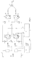
- Figure 1 is a diagrammatic illustration of a system that has two main inverters and two additional inverters.
- Figure 2 illustrates an example of a known inverter that can be used when practicing the invention.
- Figure 3 illustrates an example of control-pulse activated voltages in an inverter according to Figure 2.
- FIG. 1 illustrates a system according to the principles of the invention, more specifically a system intended for railroad operations.
- a direct-current source 1, 2 delivers two three-phase alternating currents to a drive-motor arrangement T on lines 5 and 6 through the medium of two inverters 3, 4.
- the drive-motor arrangement T may include one or more drive motors.
- the inverters can be connected by means of disconnecting switches 7 and are controlled with pulses from a control unit C via lines 9, wherein the control unit can obtain speed signals from the drive unit T via a line 9a, particularly in the case of railroad vehicles, therewith enabling the frequency of the alternating current to be adapted to motor speed.
- the direct-current voltage is divided equally between the two inverters 3 and 4. In principle, this will apply automatically provided that the inverters have mutually the same load on the alternating current sides.
- auxiliary power system Parallel with this array of main inverters intended for the drive motors T is an auxiliary power system which includes two further inverters 10, 11 which are also mutually connected in series to the same DC source 1, 2.
- the alternating current outputs of these inverters are each connected to a respective primary winding of a transformer 12, the secondary windings of which deliver three-phase current in lines 13 for general use, such as for lighting, fans, etc.
- These inverters can also be disconnected by disconnecting switches 7 and are controlled by the control unit (C) such as to obtain in principle a constant system frequency (50 or 60 Hz).
- the three-phase transformer is something special, since it is provided with three winding arrays, two three-phase "primary windings" and a three-phase secondary winding.
- the transformation ratio between the "primary windings” will preferably be 1:1, whereas the transformation ratios to the secondary windings are given by the desired service voltage.
- each primary winding shall deliver 150 kVA.
- the junction points of the alternating current sides between respective pairs of inverters 3, 4 and 10, 11 are connected to a line 14.
- the division of the direct-current voltage U Line between the inverters 3 and 4 will be the same as that between the inverters 10 and 11.
- the power output of the motor unit T is 3 MW, whereas the power output for the auxiliary power from the transformer 12 may be only 300 kW.
- one of the alternating current lines, for instance the line 5 is subjected to a lower load than the other line (something which may happen with slipping), it is possible that the direct current through the inverter 3 will tend to decrease.
- this is compensated for by the inverter 10 drawing more current and therewith delivering more power to the transformer 12.
- This surplus power will primarily reduce the power outtake from the inverter 11, the direct current of which will decrease.
- the line 14 is therewith able to deliver surplus current corresponding to the difference between the direct currents through the inverters 10 and 11 to the point 8, and therewith enable the inverter 4 to obtain more direct current than that which passes through the inverter 3.
- the inverter is duly isolated although in a more pronounced fashion, such that the inverter 10 will deliver, through the transformer 12, a positive power to the inverter 11, the direct current of which is therewith directed to the input voltage, and hence the inverter 4 will be supplied with direct current from both inverters 10 and 11.
- the direct current through the inverter will be 500 A since a current of 350 A is delivered through the inverter 10 and through the inverter 11, which delivers current from the negative pole of the direct current source to the line 14, 150 A.
- the power taken up by the inverter 10 is divided on the output from the secondary side of the transformer and on a supply to the direct current side of the inverter 4.
- the transformer will transform 375 kVA in normal operation, but will transform 656 kVA when performing under the thus dimensioned redundancy, corresponding to what is supplied from the supplying primary winding set-up. It is thus evident that when practicing the invention, there is required a particular type of transformer which is dimensioned for the purpose and the two primary windings of which are capable of withstanding more than three times the load in the case of redundancy.
- Figure 1 illustrates in broken lines two further main inverters which are connected pair-wise in series to the same direct current source.
- This modified embodiment may be appropriate for a locomotive having four motor-provided drive axles, each of which thus obtains driving power from a respective main inverter of the four main inverters provided.
- the advantages afforded by the invention will also be obtained in this case, as the skilled person will understand.
- An emergency traction power which is some percentage higher can then be obtained should one of the main inverters malfunction.
- the voltage will be equalized between series-connected main inverters when the power outtake is uneven as a result of slipping, for instance.
- pulsewidth modulation More complicated pulse modulations are known, which give less harmonics contents.
- more complicated pulse modulations which are used at relatively low levels with the fundamental harmonic of the alternating-current voltage, a switch is made relatively more often between the two valves in one phase. This method is known generally as pulsewidth modulation.
Landscapes
- Engineering & Computer Science (AREA)
- Mechanical Engineering (AREA)
- Sustainable Development (AREA)
- Sustainable Energy (AREA)
- Power Engineering (AREA)
- Transportation (AREA)
- Life Sciences & Earth Sciences (AREA)
- Stand-By Power Supply Arrangements (AREA)
- Electric Propulsion And Braking For Vehicles (AREA)
- Networks Using Active Elements (AREA)
- Supplying Of Containers To The Packaging Station (AREA)
- Control Of Motors That Do Not Use Commutators (AREA)
- Supply And Distribution Of Alternating Current (AREA)
- Inverter Devices (AREA)
Abstract
Description
Claims (5)
- An inverter arrangement having a direct-current input (1, 2) and at least two alternating-current outputs (5, 6), each being supplied from a respective main inverter (3, 4) which are connected in series to the direct current input, wherein the alternating current outputs of said inverters are connected to at least one motor (T), and an inverter control unit (C), characterized in that each said main inverter (3, 4) is connected in parallel with an auxiliary inverter (10, 11); in that the alternating current outputs of the auxiliary inverters are connected to a common transformer (12), wherein the transformer is constructed to transfer alternating current power from one of the auxiliary inverters, whose corresponding parallel-connected main inverter is out of operation, to at least one other auxiliary inverter; and in that the control unit (C) is adapted to control at least the auxiliary inverters by means of pulsewidth modulation in a four quadrant operation, enabling electric power to be delivered from an auxiliary inverter, whose corresponding parallel-connected main inverter is out of operation, via the transformer and via the alternating current output of at least one other auxiliary inverter to the direct current input of this latter inverter.
- An arrangement according to Claim 1, characterized in that the main inverters are two in number.
- An arrangement according to Claim 1 or 2, characterized in that all inverters are voltage rigid.
- An arrangement according to any one of Claims 1-3, characterized in that a speed sensing signal (9a) is applied from said at least one motor to the inverter control unit (C) so as to adjust the main inverter to a speed-dependent frequency.
- An arrangement according to any of claims 1-4, characterized in that disconnecting switches (7)are arranged for disconnecting or isolating each of said main inventers (3, 4)in case of its failure.
Applications Claiming Priority (2)
| Application Number | Priority Date | Filing Date | Title |
|---|---|---|---|
| SE9303190 | 1993-09-30 | ||
| SE9303190A SE502191C2 (en) | 1993-09-30 | 1993-09-30 | Method and apparatus for compensating the failure of an inverter |
Publications (2)
| Publication Number | Publication Date |
|---|---|
| EP0646487A1 EP0646487A1 (en) | 1995-04-05 |
| EP0646487B1 true EP0646487B1 (en) | 1998-08-12 |
Family
ID=20391265
Family Applications (1)
| Application Number | Title | Priority Date | Filing Date |
|---|---|---|---|
| EP94850167A Expired - Lifetime EP0646487B1 (en) | 1993-09-30 | 1994-09-29 | Apparatus for compensation of a malfunctioning inverter |
Country Status (4)
| Country | Link |
|---|---|
| EP (1) | EP0646487B1 (en) |
| AT (1) | ATE169572T1 (en) |
| DE (1) | DE69412408T2 (en) |
| SE (1) | SE502191C2 (en) |
Cited By (1)
| Publication number | Priority date | Publication date | Assignee | Title |
|---|---|---|---|---|
| US9991767B2 (en) | 2014-12-30 | 2018-06-05 | Progress Rail Services Corporation | Head end power module having two inverters |
Families Citing this family (3)
| Publication number | Priority date | Publication date | Assignee | Title |
|---|---|---|---|---|
| DE19610800C1 (en) * | 1996-03-19 | 1997-07-24 | Siemens Ag | Fault-tolerant traction drive converter for rail vehicles |
| DE29715187U1 (en) * | 1997-06-23 | 1998-02-05 | AFT-Automatisierungs- und Fördertechnik GmbH, 79650 Schopfheim | Floor conveyor system with track-guided industrial trucks |
| JP5017163B2 (en) * | 2008-04-01 | 2012-09-05 | 株式会社日立製作所 | Railway vehicle drive system |
Family Cites Families (2)
| Publication number | Priority date | Publication date | Assignee | Title |
|---|---|---|---|---|
| EP0284869B1 (en) * | 1987-03-31 | 1991-10-16 | Siemens Aktiengesellschaft | Power supply circuit using dc series supply |
| JPH0583948A (en) * | 1991-09-13 | 1993-04-02 | East Japan Railway Co | Vehicle drive |
-
1993
- 1993-09-30 SE SE9303190A patent/SE502191C2/en not_active IP Right Cessation
-
1994
- 1994-09-29 DE DE69412408T patent/DE69412408T2/en not_active Expired - Fee Related
- 1994-09-29 AT AT94850167T patent/ATE169572T1/en not_active IP Right Cessation
- 1994-09-29 EP EP94850167A patent/EP0646487B1/en not_active Expired - Lifetime
Cited By (1)
| Publication number | Priority date | Publication date | Assignee | Title |
|---|---|---|---|---|
| US9991767B2 (en) | 2014-12-30 | 2018-06-05 | Progress Rail Services Corporation | Head end power module having two inverters |
Also Published As
| Publication number | Publication date |
|---|---|
| DE69412408D1 (en) | 1998-09-17 |
| SE9303190L (en) | 1995-03-31 |
| SE502191C2 (en) | 1995-09-11 |
| SE9303190D0 (en) | 1993-09-30 |
| ATE169572T1 (en) | 1998-08-15 |
| DE69412408T2 (en) | 1999-04-29 |
| EP0646487A1 (en) | 1995-04-05 |
Similar Documents
| Publication | Publication Date | Title |
|---|---|---|
| US12028009B2 (en) | Protection system for aircraft electric propulsion motor and motor controller | |
| CN107112765B (en) | Power distribution on a ship | |
| US9991719B2 (en) | Systems and methods for reducing circulating current and phase to phase imbalance in a parallel modular converter system | |
| US7508147B2 (en) | Variable-frequency drive with regeneration capability | |
| US9941772B2 (en) | Marine propulsion systems | |
| EP1029732A2 (en) | Apparatus for driving a car using inverter-controlled motors and a gear mechanism | |
| US9793710B2 (en) | Energy storing device with cooling elements, and method for cooling energy storing cells | |
| WO2008081189A1 (en) | Power systems | |
| JPH11318086A (en) | Stationary power converter supplied with unlimited voltage | |
| CA2097972A1 (en) | Ac variable speed driving apparatus and electric vehicle using the same | |
| US11025069B2 (en) | System for distributing mixed DC and AC electrical power for supplying variable frequency loads and fixed frequency loads | |
| US5629591A (en) | High-availability multicurrent power supply system for the traction unit of a railway locomotive | |
| MX2007014842A (en) | Inverter operation with over-modulation. | |
| GB2050089A (en) | Traction equipment | |
| EP0646487A1 (en) | A method and apparatus for compensation of a malfunctioning inverter | |
| JP2023540699A (en) | Apparatus and method for operating a three-level or multilevel inverter | |
| SE441733B (en) | DRIVE SYSTEM FOR ELECTRIC TRANSMISSION OF A TRUCK VEHICLE WITH A MEDFORD ENERGY CELL | |
| US5339235A (en) | Fault compensating multi-step wave inverter | |
| CA2933979A1 (en) | Motor control center including an integrated dual bus configuration | |
| US8373301B2 (en) | System and method for providing power to two loads from a single three-phase inverter | |
| PL174478B1 (en) | Circuit arrangement of a current converter used to provide power for a dc circuit | |
| JPH0851703A (en) | PWM converter control method | |
| US6297978B1 (en) | Bypass rectifier connection for alternator transition locomotives | |
| JP3675124B2 (en) | Control device for pulse width modulation control converter | |
| JP2592536B2 (en) | Power converter control device |
Legal Events
| Date | Code | Title | Description |
|---|---|---|---|
| PUAI | Public reference made under article 153(3) epc to a published international application that has entered the european phase |
Free format text: ORIGINAL CODE: 0009012 |
|
| AK | Designated contracting states |
Kind code of ref document: A1 Designated state(s): AT CH DE DK ES FR GB IT LI PT |
|
| 17P | Request for examination filed |
Effective date: 19950921 |
|
| 17Q | First examination report despatched |
Effective date: 19961227 |
|
| GRAG | Despatch of communication of intention to grant |
Free format text: ORIGINAL CODE: EPIDOS AGRA |
|
| GRAG | Despatch of communication of intention to grant |
Free format text: ORIGINAL CODE: EPIDOS AGRA |
|
| GRAH | Despatch of communication of intention to grant a patent |
Free format text: ORIGINAL CODE: EPIDOS IGRA |
|
| GRAH | Despatch of communication of intention to grant a patent |
Free format text: ORIGINAL CODE: EPIDOS IGRA |
|
| GRAA | (expected) grant |
Free format text: ORIGINAL CODE: 0009210 |
|
| AK | Designated contracting states |
Kind code of ref document: B1 Designated state(s): AT CH DE DK ES FR GB IT LI PT |
|
| PG25 | Lapsed in a contracting state [announced via postgrant information from national office to epo] |
Ref country code: LI Free format text: LAPSE BECAUSE OF FAILURE TO SUBMIT A TRANSLATION OF THE DESCRIPTION OR TO PAY THE FEE WITHIN THE PRESCRIBED TIME-LIMIT Effective date: 19980812 Ref country code: IT Free format text: LAPSE BECAUSE OF FAILURE TO SUBMIT A TRANSLATION OF THE DESCRIPTION OR TO PAY THE FEE WITHIN THE PRESCRIBED TIME-LIMIT;WARNING: LAPSES OF ITALIAN PATENTS WITH EFFECTIVE DATE BEFORE 2007 MAY HAVE OCCURRED AT ANY TIME BEFORE 2007. THE CORRECT EFFECTIVE DATE MAY BE DIFFERENT FROM THE ONE RECORDED. Effective date: 19980812 Ref country code: FR Free format text: LAPSE BECAUSE OF FAILURE TO SUBMIT A TRANSLATION OF THE DESCRIPTION OR TO PAY THE FEE WITHIN THE PRESCRIBED TIME-LIMIT Effective date: 19980812 Ref country code: CH Free format text: LAPSE BECAUSE OF FAILURE TO SUBMIT A TRANSLATION OF THE DESCRIPTION OR TO PAY THE FEE WITHIN THE PRESCRIBED TIME-LIMIT Effective date: 19980812 Ref country code: AT Free format text: LAPSE BECAUSE OF FAILURE TO SUBMIT A TRANSLATION OF THE DESCRIPTION OR TO PAY THE FEE WITHIN THE PRESCRIBED TIME-LIMIT Effective date: 19980812 |
|
| REF | Corresponds to: |
Ref document number: 169572 Country of ref document: AT Date of ref document: 19980815 Kind code of ref document: T |
|
| REG | Reference to a national code |
Ref country code: CH Ref legal event code: EP |
|
| PGFP | Annual fee paid to national office [announced via postgrant information from national office to epo] |
Ref country code: FR Payment date: 19980909 Year of fee payment: 5 |
|
| PGFP | Annual fee paid to national office [announced via postgrant information from national office to epo] |
Ref country code: DK Payment date: 19980914 Year of fee payment: 5 Ref country code: AT Payment date: 19980914 Year of fee payment: 5 |
|
| REF | Corresponds to: |
Ref document number: 69412408 Country of ref document: DE Date of ref document: 19980917 |
|
| PGFP | Annual fee paid to national office [announced via postgrant information from national office to epo] |
Ref country code: ES Payment date: 19980921 Year of fee payment: 5 |
|
| PGFP | Annual fee paid to national office [announced via postgrant information from national office to epo] |
Ref country code: GB Payment date: 19981001 Year of fee payment: 5 |
|
| PGFP | Annual fee paid to national office [announced via postgrant information from national office to epo] |
Ref country code: CH Payment date: 19981009 Year of fee payment: 5 |
|
| PG25 | Lapsed in a contracting state [announced via postgrant information from national office to epo] |
Ref country code: PT Free format text: LAPSE BECAUSE OF FAILURE TO SUBMIT A TRANSLATION OF THE DESCRIPTION OR TO PAY THE FEE WITHIN THE PRESCRIBED TIME-LIMIT Effective date: 19981112 Ref country code: DK Free format text: LAPSE BECAUSE OF FAILURE TO SUBMIT A TRANSLATION OF THE DESCRIPTION OR TO PAY THE FEE WITHIN THE PRESCRIBED TIME-LIMIT Effective date: 19981112 |
|
| EN | Fr: translation not filed | ||
| PG25 | Lapsed in a contracting state [announced via postgrant information from national office to epo] |
Ref country code: ES Free format text: LAPSE BECAUSE OF FAILURE TO SUBMIT A TRANSLATION OF THE DESCRIPTION OR TO PAY THE FEE WITHIN THE PRESCRIBED TIME-LIMIT Effective date: 19990219 |
|
| REG | Reference to a national code |
Ref country code: CH Ref legal event code: PL |
|
| PLBE | No opposition filed within time limit |
Free format text: ORIGINAL CODE: 0009261 |
|
| STAA | Information on the status of an ep patent application or granted ep patent |
Free format text: STATUS: NO OPPOSITION FILED WITHIN TIME LIMIT |
|
| 26N | No opposition filed | ||
| PG25 | Lapsed in a contracting state [announced via postgrant information from national office to epo] |
Ref country code: GB Free format text: LAPSE BECAUSE OF NON-PAYMENT OF DUE FEES Effective date: 19990929 |
|
| GBPC | Gb: european patent ceased through non-payment of renewal fee |
Effective date: 19990929 |
|
| PGFP | Annual fee paid to national office [announced via postgrant information from national office to epo] |
Ref country code: DE Payment date: 20020827 Year of fee payment: 9 |
|
| PG25 | Lapsed in a contracting state [announced via postgrant information from national office to epo] |
Ref country code: DE Free format text: LAPSE BECAUSE OF NON-PAYMENT OF DUE FEES Effective date: 20040401 |