EP0645796B1 - Cathode ray tube apparatus - Google Patents
Cathode ray tube apparatus Download PDFInfo
- Publication number
- EP0645796B1 EP0645796B1 EP94402173A EP94402173A EP0645796B1 EP 0645796 B1 EP0645796 B1 EP 0645796B1 EP 94402173 A EP94402173 A EP 94402173A EP 94402173 A EP94402173 A EP 94402173A EP 0645796 B1 EP0645796 B1 EP 0645796B1
- Authority
- EP
- European Patent Office
- Prior art keywords
- screening area
- thickness
- panel
- effective screening
- ray tube
- Prior art date
- Legal status (The legal status is an assumption and is not a legal conclusion. Google has not performed a legal analysis and makes no representation as to the accuracy of the status listed.)
- Expired - Lifetime
Links
Images


Classifications
-
- H—ELECTRICITY
- H01—ELECTRIC ELEMENTS
- H01J—ELECTRIC DISCHARGE TUBES OR DISCHARGE LAMPS
- H01J29/00—Details of cathode-ray tubes or of electron-beam tubes of the types covered by group H01J31/00
- H01J29/02—Electrodes; Screens; Mounting, supporting, spacing or insulating thereof
-
- H—ELECTRICITY
- H01—ELECTRIC ELEMENTS
- H01J—ELECTRIC DISCHARGE TUBES OR DISCHARGE LAMPS
- H01J29/00—Details of cathode-ray tubes or of electron-beam tubes of the types covered by group H01J31/00
- H01J29/86—Vessels; Containers; Vacuum locks
- H01J29/861—Vessels or containers characterised by the form or the structure thereof
-
- H—ELECTRICITY
- H01—ELECTRIC ELEMENTS
- H01J—ELECTRIC DISCHARGE TUBES OR DISCHARGE LAMPS
- H01J2229/00—Details of cathode ray tubes or electron beam tubes
- H01J2229/86—Vessels and containers
- H01J2229/8613—Faceplates
- H01J2229/8616—Faceplates characterised by shape
Definitions
- This invention relates to a projection television CRT (cathode-ray tube), the CRT having a panel which is convex on the inside (a panel display).
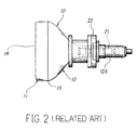
- FIG. 1 illustrates a projector in the related art.
- a video image displayed on a CRT for projecting 2 is magnified by a lens 3, reflected from a mirror 4, and projected onto a screen 5.
- the CRT for projecting 2 comprises a glass tube 10 for displaying the video image, an electron gun 21 built into the glass tube 10, a deflection yoke 22, and so on.
- the glass tube 10 consists of a panel 11 which is rectangular in shape in front having a display area 14 onto the inside of which a phosphor is coated, and a funnel 12.
- a frit seal 13 is welded between the panel 11 and the funnel 12 so that the glass tube 10 is closed tightly.
- the electron gun 21 mounted in the neck 12A of the funnel 12 emits an electron beam, corresponding to a video signal, which is deflected by the deflection yoke 22 and scanned horizontally and vertically so as to be projected onto the phosphor inside the display area 14. In such fashion, the video image is displayed in the display area 14.
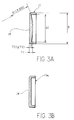
- the panel 11 is either a panel 11 convex on the inside, as illustrated in FIG. 3A, or a panel 11a flat on the inside, as illustrated in FIG. 3B.
- the inside portion of the display area 14 of the panel 11 convex on the inside protrudes inward in an arc shape, extending in all directions with a predetermined radius R1 of, for example, approximately 350 mm.
- R1 a predetermined radius of, for example, approximately 350 mm.
- the inside portion of the display area 14 is a part of a spherical surface.
- the inside portion of the display area 14 is flat on the inside.
- the thickness T1 of the center of the display area 14 is fixed based on optical conditions, and the thickness T2 of the peripheral area surrounding the display area 14 must be set at a greater thickness than the standard thickness Tf of, for example, 5 to 6 mm. In this way, the size of the effective screening area of the display area in which the video image is normally displayed is restricted.
- the problem described above is solved by a projection CRT, according to claim 1.
- the CRT according to the present invention having a panel convex on the inside, has the effective screening area having a thickness greater than the standard thickness, and the non-screening area, which is outside the effective screening area and formed such that the inside portion of the non-screening area is flat or protuberant so as to allow the non-screening area to have a thickness greater than the standard thickness.
- a projection television CRT is described below with reference to the drawings.
- the inside portion of the effective screening area A2 inside the rectangular display area 14 of the panel 11 protrudes inward in an arc shape, extending in all directions, at a predetermined radius R1 and has a predetermined thickness T1 at the center.
- the four corners of the display area 14 are outside of a circular boundary line 31 that establishes the standard thickness Tf for the strength necessary to allow for normal usage without breaking.
- Non-screening areas H which are outside the boundary line 31 and outside the predetermined radius R1 are flat or protuberant and have a greater thickness than the standard thickness Tf.
- the effective screening area of the panel 11 can be made larger than the conventional effective screening area A1, which conventional effective screening area had to be smaller than the boundary line 31, including the four comers, while maintaining necessary strength.
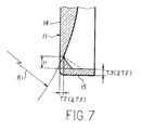
- FIG.7 One embodiment of a projection television CRT, according to this invention, is described below with reference to Figs.4 to 6 and a second embodiment is illustrated by Fig.7.
- the same reference numerals will denote the parts previously described, and detailed descriptions will be omitted.
- FIG. 4 illustrates the structure of a projection television CRT 2 in accordance with this invention.
- the CRT for projecting 2 comprises a glass tube 10, an electron gun 21 built in the glass tube 10, a deflection yoke 22, and so on.
- the glass tube 10 consists of a panel 11 convex on the inside and a funnel 12.
- a frit seal 13 is welded between the panel 11 and the funnel 12 so that the glass tube 10 is closed tightly.
- the electron gun 21 and the deflection yoke 22 are mounted in the neck 12A of the funnel 12.
- the panel 11 comprises the rectangular display area 14 and the rim 15 surrounding the display area 14.
- FIG. 4 is a vertical cross-sectional view (above the center line C) and a diagonal cross-sectional view (below the center line C) of the panel 11.
- the display area 14 is a part of the spherical surface, excluding four corners of the non-screening areas H.
- the center portion of the display area 14 has a predetermined thickness T1, and the thickness T2 of the non-screening areas H and the thickness T3 of the rim 15 are greater than the thickness of the standard thickness Tf.
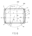
- the panel 11 has a boundary line 31 describing a circle with center at the center of the display area 14 with a radius R2, and has the standard thickness Tf at the circumference as shown in FIG.5.
- the radius R2 of the boundary line 31 is determined by the radius R1 of the protruding arc and the thickness T1 of the center of the display area 14.
- the conventional effective screening area A1 is small, including the four comers, as shown with a dotted line.
- the non-screening areas H are outside the boundary line 31 as indicated by a oblique lines, and the inside portions of the non-screening areas H, as shown in FIG 4, are outside of the sphere with the radius R1, are flat and have thickness T2 which is greater than the standard thickness Tf.
- the four comers of the display area 14 of the panel 11 are located outside of the boundary line 31.
- the inside portion of the non-screening areas H is outside of the radius R1 and flat.
- the thickness of the non-screening area H is greater than the standard thickness Tf. Accordingly, the effective screening area A2 can be made larger while maintaining necessary strength.
- a first effective screening area 32A is set with its four corners at the circumference of the boundary line 31, so that the panel 11 displays a video image at an aspect ratio 4:3.
- a second effective screening area 32B is set to fall at right angles with the first effective screening area 32A so that the panel 11 displays a video image at an aspect ratio 16:9.
- the effective screening area A2 corresponds to the outline consisting of the four outer lines of the effective screening areas 32A or 32B, in other words, the upper and lower side lines of the first effective screening area and the right and left side lines of the second effective screening area 32B.
- the inside portion of the non-screening areas H is flat, it may also protrude outside of the sphere with the radius R1 as drawn with a solid or broken line in FIG. 7.
- the inside portion of the effective screening area protrudes inward in an arc shape, extending in all directions, with a predetermined radius, and has a greater thickness than a predetermined standard thickness.
- the inside portion of the non-screening area, which is outside said effective screening area, is outside of the circle of predetermined radius and flat or protuberant, and has a greater thickness than the predetermined standard thickness. Accordingly, through this invention, the effective screening area can be made larger than the conventional types while maintaining necessary strength.
Description
Claims (5)
- A projection television cathode ray tube apparatus, having a panel (11) formed such that an inside portion of an effective screening area (A2) that displays video images protrudes inward in an arc shape, extending in all directions, wherein :said inside portion of said effective screening area (A2), in addition to protruding inward in an arc shape at a predetermined radius (R1), has a thickness greater than a predetermined standard thickness (Tf); andan inside portion of a non-screening area (H), located outside of said effective screening area (A2), is outside of the arc formed by said predetermined radius (R1), is flat or protuberant, and has a thickness (T2) greater than said standard thickness (Tf).
- The cathode ray tube apparatus in accordance with claim 1, wherein the outlines for said effective screening area (A2) comprise:upper and lower outlines for a first effective screening area (32A) which displays video images of a first aspect ratio; andright and left outlines for a second effective screening area (32B) which displays video images of a second aspect ratio.
- The cathode ray tube apparatus in accordance with claim 2, wherein said non-screening area (H) is set outside a circle (31) circumscribed about said first aspect with its center at the center of said panel.
- The cathode ray tube apparatus in accordance with claim 2, wherein non-screening areas (H) are set in the four corners of said panel (11), outside said effective screening area (A2) which has said first and second aspect ratios.
- The cathode ray tube apparatus in accordance with claim 1, wherein the thickness on a boundary line (31) between said effective screening area (A2) and said non-screening area (H) is equal to said standard thickness (Tf).
Applications Claiming Priority (2)
| Application Number | Priority Date | Filing Date | Title |
|---|---|---|---|
| JP243344/93 | 1993-09-29 | ||
| JP24334493A JP3427440B2 (en) | 1993-09-29 | 1993-09-29 | Cathode ray tube for projector |
Publications (3)
| Publication Number | Publication Date |
|---|---|
| EP0645796A2 EP0645796A2 (en) | 1995-03-29 |
| EP0645796A3 EP0645796A3 (en) | 1996-10-30 |
| EP0645796B1 true EP0645796B1 (en) | 1998-07-15 |
Family
ID=17102435
Family Applications (1)
| Application Number | Title | Priority Date | Filing Date |
|---|---|---|---|
| EP94402173A Expired - Lifetime EP0645796B1 (en) | 1993-09-29 | 1994-09-29 | Cathode ray tube apparatus |
Country Status (5)
| Country | Link |
|---|---|
| US (1) | US5552663A (en) |
| EP (1) | EP0645796B1 (en) |
| JP (1) | JP3427440B2 (en) |
| KR (1) | KR950009855A (en) |
| DE (1) | DE69411650T2 (en) |
Families Citing this family (5)
| Publication number | Priority date | Publication date | Assignee | Title |
|---|---|---|---|---|
| JP2993437B2 (en) * | 1996-08-23 | 1999-12-20 | ソニー株式会社 | Glass bulb for color picture tube and color picture tube |
| DE69918874T2 (en) * | 1998-01-30 | 2005-07-21 | Hitachi, Ltd. | cathode ray tube |
| KR100267963B1 (en) * | 1998-08-17 | 2000-10-16 | 구자홍 | Cathode ray panel |
| WO2000067284A1 (en) * | 1999-04-28 | 2000-11-09 | Hitachi, Ltd. | Color cathode-ray tube |
| KR100839407B1 (en) * | 2002-01-21 | 2008-06-19 | 삼성에스디아이 주식회사 | Monochrome cathode ray tube for projection system and manufacturing method of the crt |
Family Cites Families (5)
| Publication number | Priority date | Publication date | Assignee | Title |
|---|---|---|---|---|
| US2172775A (en) * | 1935-01-30 | 1939-09-12 | Telefunken Gmbh | Optical system |
| US4409515A (en) * | 1978-02-06 | 1983-10-11 | Kloss Henry E | Projection television tube and process for forming same |
| DE3475140D1 (en) * | 1984-06-01 | 1988-12-15 | Philips Nv | Projection cathode ray tube and image display device provided with such a tube |
| US4904899A (en) * | 1987-06-26 | 1990-02-27 | Asahi Glass Company Ltd. | Projection cathode ray tube |
| JPH05341167A (en) * | 1992-06-08 | 1993-12-24 | Matsushita Electric Ind Co Ltd | Lens holding member and formation of thin film |
-
1993
- 1993-09-29 JP JP24334493A patent/JP3427440B2/en not_active Expired - Fee Related
-
1994
- 1994-09-22 US US08/310,325 patent/US5552663A/en not_active Expired - Fee Related
- 1994-09-24 KR KR1019940024052A patent/KR950009855A/en not_active Application Discontinuation
- 1994-09-29 DE DE69411650T patent/DE69411650T2/en not_active Expired - Fee Related
- 1994-09-29 EP EP94402173A patent/EP0645796B1/en not_active Expired - Lifetime
Also Published As
| Publication number | Publication date |
|---|---|
| JP3427440B2 (en) | 2003-07-14 |
| EP0645796A3 (en) | 1996-10-30 |
| DE69411650D1 (en) | 1998-08-20 |
| KR950009855A (en) | 1995-04-26 |
| JPH0799029A (en) | 1995-04-11 |
| EP0645796A2 (en) | 1995-03-29 |
| US5552663A (en) | 1996-09-03 |
| DE69411650T2 (en) | 1998-11-05 |
Similar Documents
| Publication | Publication Date | Title |
|---|---|---|
| US6002203A (en) | Cathode ray tube having an envelope shaped to reduce beam deflection power requirements | |
| US6459196B1 (en) | Cathode-ray tube | |
| US6639345B2 (en) | Color cathode ray tube | |
| EP0645796B1 (en) | Cathode ray tube apparatus | |
| US6384525B1 (en) | Cathode-ray tube having a non-circular yoke section | |
| JP2002042671A (en) | Color picture tube | |
| US6208067B1 (en) | Color cathode ray tube | |
| US6664724B2 (en) | Shadow mask for color CRT | |
| JP2001236898A (en) | Internal magnetic shield and cathode-ray tube | |
| KR20020091804A (en) | Color cathod ray tube having improved color purity | |
| US6680565B2 (en) | Cathode-ray tube | |
| US7105993B2 (en) | Shadow mask for cathode ray tube having an aperture area in which a curvature of radii in the horizontal and vertical directions satisfy a particular condition | |
| JP2928035B2 (en) | Cathode ray tube | |
| US6774553B2 (en) | Cathode-ray tube | |
| US20060097619A1 (en) | Projection-type cathode ray tube | |
| JP2644221B2 (en) | Cathode ray tube device | |
| US6342757B1 (en) | Cathode ray tube for multimedia | |
| JPH0251831A (en) | Cathode-ray tube | |
| US5757120A (en) | Color cathode ray tube with decenterable magnetic body | |
| KR950001083B1 (en) | Crt | |
| JP2000340132A (en) | Color cathode-ray tube | |
| US20030146685A1 (en) | Cathode ray tube | |
| JP3178943B2 (en) | Picture tube device | |
| JPH11260293A (en) | Cathode-ray tube | |
| KR100607245B1 (en) | Shadow mask of CRT |
Legal Events
| Date | Code | Title | Description |
|---|---|---|---|
| PUAI | Public reference made under article 153(3) epc to a published international application that has entered the european phase |
Free format text: ORIGINAL CODE: 0009012 |
|
| AK | Designated contracting states |
Kind code of ref document: A2 Designated state(s): DE FR GB |
|
| PUAL | Search report despatched |
Free format text: ORIGINAL CODE: 0009013 |
|
| AK | Designated contracting states |
Kind code of ref document: A3 Designated state(s): DE FR GB |
|
| 17P | Request for examination filed |
Effective date: 19970408 |
|
| GRAG | Despatch of communication of intention to grant |
Free format text: ORIGINAL CODE: EPIDOS AGRA |
|
| 17Q | First examination report despatched |
Effective date: 19970820 |
|
| GRAG | Despatch of communication of intention to grant |
Free format text: ORIGINAL CODE: EPIDOS AGRA |
|
| GRAG | Despatch of communication of intention to grant |
Free format text: ORIGINAL CODE: EPIDOS AGRA |
|
| GRAH | Despatch of communication of intention to grant a patent |
Free format text: ORIGINAL CODE: EPIDOS IGRA |
|
| GRAH | Despatch of communication of intention to grant a patent |
Free format text: ORIGINAL CODE: EPIDOS IGRA |
|
| GRAA | (expected) grant |
Free format text: ORIGINAL CODE: 0009210 |
|
| AK | Designated contracting states |
Kind code of ref document: B1 Designated state(s): DE FR GB |
|
| REF | Corresponds to: |
Ref document number: 69411650 Country of ref document: DE Date of ref document: 19980820 |
|
| ET | Fr: translation filed | ||
| PLBE | No opposition filed within time limit |
Free format text: ORIGINAL CODE: 0009261 |
|
| STAA | Information on the status of an ep patent application or granted ep patent |
Free format text: STATUS: NO OPPOSITION FILED WITHIN TIME LIMIT |
|
| 26N | No opposition filed | ||
| PGFP | Annual fee paid to national office [announced via postgrant information from national office to epo] |
Ref country code: FR Payment date: 20010911 Year of fee payment: 8 |
|
| PGFP | Annual fee paid to national office [announced via postgrant information from national office to epo] |
Ref country code: GB Payment date: 20011003 Year of fee payment: 8 |
|
| PGFP | Annual fee paid to national office [announced via postgrant information from national office to epo] |
Ref country code: DE Payment date: 20011015 Year of fee payment: 8 |
|
| REG | Reference to a national code |
Ref country code: GB Ref legal event code: IF02 |
|
| PG25 | Lapsed in a contracting state [announced via postgrant information from national office to epo] |
Ref country code: GB Free format text: LAPSE BECAUSE OF NON-PAYMENT OF DUE FEES Effective date: 20020929 |
|
| PG25 | Lapsed in a contracting state [announced via postgrant information from national office to epo] |
Ref country code: DE Free format text: LAPSE BECAUSE OF NON-PAYMENT OF DUE FEES Effective date: 20030401 |
|
| GBPC | Gb: european patent ceased through non-payment of renewal fee |
Effective date: 20020929 |
|
| PG25 | Lapsed in a contracting state [announced via postgrant information from national office to epo] |
Ref country code: FR Free format text: LAPSE BECAUSE OF NON-PAYMENT OF DUE FEES Effective date: 20030603 |
|
| REG | Reference to a national code |
Ref country code: FR Ref legal event code: ST |