EP0644360A1 - Manual modification of automatic mode shift points - Google Patents
Manual modification of automatic mode shift points Download PDFInfo
- Publication number
- EP0644360A1 EP0644360A1 EP94306786A EP94306786A EP0644360A1 EP 0644360 A1 EP0644360 A1 EP 0644360A1 EP 94306786 A EP94306786 A EP 94306786A EP 94306786 A EP94306786 A EP 94306786A EP 0644360 A1 EP0644360 A1 EP 0644360A1
- Authority
- EP
- European Patent Office
- Prior art keywords
- value
- engine speed
- upshift
- downshift
- transmission
- Prior art date
- Legal status (The legal status is an assumption and is not a legal conclusion. Google has not performed a legal analysis and makes no representation as to the accuracy of the status listed.)
- Granted
Links
Images


Classifications
-
- F—MECHANICAL ENGINEERING; LIGHTING; HEATING; WEAPONS; BLASTING
- F16—ENGINEERING ELEMENTS AND UNITS; GENERAL MEASURES FOR PRODUCING AND MAINTAINING EFFECTIVE FUNCTIONING OF MACHINES OR INSTALLATIONS; THERMAL INSULATION IN GENERAL
- F16H—GEARING
- F16H59/00—Control inputs to control units of change-speed-, or reversing-gearings for conveying rotary motion
- F16H59/02—Selector apparatus
- F16H59/08—Range selector apparatus
-
- F—MECHANICAL ENGINEERING; LIGHTING; HEATING; WEAPONS; BLASTING
- F16—ENGINEERING ELEMENTS AND UNITS; GENERAL MEASURES FOR PRODUCING AND MAINTAINING EFFECTIVE FUNCTIONING OF MACHINES OR INSTALLATIONS; THERMAL INSULATION IN GENERAL
- F16H—GEARING
- F16H59/00—Control inputs to control units of change-speed-, or reversing-gearings for conveying rotary motion
-
- F—MECHANICAL ENGINEERING; LIGHTING; HEATING; WEAPONS; BLASTING
- F16—ENGINEERING ELEMENTS AND UNITS; GENERAL MEASURES FOR PRODUCING AND MAINTAINING EFFECTIVE FUNCTIONING OF MACHINES OR INSTALLATIONS; THERMAL INSULATION IN GENERAL
- F16H—GEARING
- F16H61/00—Control functions within control units of change-speed- or reversing-gearings for conveying rotary motion ; Control of exclusively fluid gearing, friction gearing, gearings with endless flexible members or other particular types of gearing
- F16H61/02—Control functions within control units of change-speed- or reversing-gearings for conveying rotary motion ; Control of exclusively fluid gearing, friction gearing, gearings with endless flexible members or other particular types of gearing characterised by the signals used
- F16H61/0202—Control functions within control units of change-speed- or reversing-gearings for conveying rotary motion ; Control of exclusively fluid gearing, friction gearing, gearings with endless flexible members or other particular types of gearing characterised by the signals used the signals being electric
- F16H61/0204—Control functions within control units of change-speed- or reversing-gearings for conveying rotary motion ; Control of exclusively fluid gearing, friction gearing, gearings with endless flexible members or other particular types of gearing characterised by the signals used the signals being electric for gearshift control, e.g. control functions for performing shifting or generation of shift signal
- F16H61/0213—Control functions within control units of change-speed- or reversing-gearings for conveying rotary motion ; Control of exclusively fluid gearing, friction gearing, gearings with endless flexible members or other particular types of gearing characterised by the signals used the signals being electric for gearshift control, e.g. control functions for performing shifting or generation of shift signal characterised by the method for generating shift signals
-
- B—PERFORMING OPERATIONS; TRANSPORTING
- B60—VEHICLES IN GENERAL
- B60W—CONJOINT CONTROL OF VEHICLE SUB-UNITS OF DIFFERENT TYPE OR DIFFERENT FUNCTION; CONTROL SYSTEMS SPECIALLY ADAPTED FOR HYBRID VEHICLES; ROAD VEHICLE DRIVE CONTROL SYSTEMS FOR PURPOSES NOT RELATED TO THE CONTROL OF A PARTICULAR SUB-UNIT
- B60W2510/00—Input parameters relating to a particular sub-units
- B60W2510/06—Combustion engines, Gas turbines
- B60W2510/0638—Engine speed
-
- F—MECHANICAL ENGINEERING; LIGHTING; HEATING; WEAPONS; BLASTING
- F16—ENGINEERING ELEMENTS AND UNITS; GENERAL MEASURES FOR PRODUCING AND MAINTAINING EFFECTIVE FUNCTIONING OF MACHINES OR INSTALLATIONS; THERMAL INSULATION IN GENERAL
- F16H—GEARING
- F16H59/00—Control inputs to control units of change-speed-, or reversing-gearings for conveying rotary motion
- F16H2059/006—Overriding automatic control
-
- F—MECHANICAL ENGINEERING; LIGHTING; HEATING; WEAPONS; BLASTING
- F16—ENGINEERING ELEMENTS AND UNITS; GENERAL MEASURES FOR PRODUCING AND MAINTAINING EFFECTIVE FUNCTIONING OF MACHINES OR INSTALLATIONS; THERMAL INSULATION IN GENERAL
- F16H—GEARING
- F16H59/00—Control inputs to control units of change-speed-, or reversing-gearings for conveying rotary motion
- F16H59/02—Selector apparatus
- F16H59/08—Range selector apparatus
- F16H2059/082—Range selector apparatus with different modes
-
- F—MECHANICAL ENGINEERING; LIGHTING; HEATING; WEAPONS; BLASTING
- F16—ENGINEERING ELEMENTS AND UNITS; GENERAL MEASURES FOR PRODUCING AND MAINTAINING EFFECTIVE FUNCTIONING OF MACHINES OR INSTALLATIONS; THERMAL INSULATION IN GENERAL
- F16H—GEARING
- F16H59/00—Control inputs to control units of change-speed-, or reversing-gearings for conveying rotary motion
- F16H59/02—Selector apparatus
- F16H59/08—Range selector apparatus
- F16H59/10—Range selector apparatus comprising levers
- F16H59/105—Range selector apparatus comprising levers consisting of electrical switches or sensors
-
- F—MECHANICAL ENGINEERING; LIGHTING; HEATING; WEAPONS; BLASTING
- F16—ENGINEERING ELEMENTS AND UNITS; GENERAL MEASURES FOR PRODUCING AND MAINTAINING EFFECTIVE FUNCTIONING OF MACHINES OR INSTALLATIONS; THERMAL INSULATION IN GENERAL
- F16H—GEARING
- F16H59/00—Control inputs to control units of change-speed-, or reversing-gearings for conveying rotary motion
- F16H59/36—Inputs being a function of speed
- F16H59/38—Inputs being a function of speed of gearing elements
- F16H59/40—Output shaft speed
-
- F—MECHANICAL ENGINEERING; LIGHTING; HEATING; WEAPONS; BLASTING
- F16—ENGINEERING ELEMENTS AND UNITS; GENERAL MEASURES FOR PRODUCING AND MAINTAINING EFFECTIVE FUNCTIONING OF MACHINES OR INSTALLATIONS; THERMAL INSULATION IN GENERAL
- F16H—GEARING
- F16H59/00—Control inputs to control units of change-speed-, or reversing-gearings for conveying rotary motion
- F16H59/36—Inputs being a function of speed
- F16H59/38—Inputs being a function of speed of gearing elements
- F16H59/42—Input shaft speed
-
- F—MECHANICAL ENGINEERING; LIGHTING; HEATING; WEAPONS; BLASTING
- F16—ENGINEERING ELEMENTS AND UNITS; GENERAL MEASURES FOR PRODUCING AND MAINTAINING EFFECTIVE FUNCTIONING OF MACHINES OR INSTALLATIONS; THERMAL INSULATION IN GENERAL
- F16H—GEARING
- F16H59/00—Control inputs to control units of change-speed-, or reversing-gearings for conveying rotary motion
- F16H59/36—Inputs being a function of speed
- F16H59/44—Inputs being a function of speed dependent on machine speed of the machine, e.g. the vehicle
-
- F—MECHANICAL ENGINEERING; LIGHTING; HEATING; WEAPONS; BLASTING
- F16—ENGINEERING ELEMENTS AND UNITS; GENERAL MEASURES FOR PRODUCING AND MAINTAINING EFFECTIVE FUNCTIONING OF MACHINES OR INSTALLATIONS; THERMAL INSULATION IN GENERAL
- F16H—GEARING
- F16H59/00—Control inputs to control units of change-speed-, or reversing-gearings for conveying rotary motion
- F16H59/36—Inputs being a function of speed
- F16H59/46—Inputs being a function of speed dependent on a comparison between speeds
-
- F—MECHANICAL ENGINEERING; LIGHTING; HEATING; WEAPONS; BLASTING
- F16—ENGINEERING ELEMENTS AND UNITS; GENERAL MEASURES FOR PRODUCING AND MAINTAINING EFFECTIVE FUNCTIONING OF MACHINES OR INSTALLATIONS; THERMAL INSULATION IN GENERAL
- F16H—GEARING
- F16H61/00—Control functions within control units of change-speed- or reversing-gearings for conveying rotary motion ; Control of exclusively fluid gearing, friction gearing, gearings with endless flexible members or other particular types of gearing
- F16H61/04—Smoothing ratio shift
- F16H61/0403—Synchronisation before shifting
-
- F—MECHANICAL ENGINEERING; LIGHTING; HEATING; WEAPONS; BLASTING
- F16—ENGINEERING ELEMENTS AND UNITS; GENERAL MEASURES FOR PRODUCING AND MAINTAINING EFFECTIVE FUNCTIONING OF MACHINES OR INSTALLATIONS; THERMAL INSULATION IN GENERAL
- F16H—GEARING
- F16H61/00—Control functions within control units of change-speed- or reversing-gearings for conveying rotary motion ; Control of exclusively fluid gearing, friction gearing, gearings with endless flexible members or other particular types of gearing
- F16H61/70—Control functions within control units of change-speed- or reversing-gearings for conveying rotary motion ; Control of exclusively fluid gearing, friction gearing, gearings with endless flexible members or other particular types of gearing specially adapted for change-speed gearing in group arrangement, i.e. with separate change-speed gear trains arranged in series, e.g. range or overdrive-type gearing arrangements
- F16H61/702—Control functions within control units of change-speed- or reversing-gearings for conveying rotary motion ; Control of exclusively fluid gearing, friction gearing, gearings with endless flexible members or other particular types of gearing specially adapted for change-speed gearing in group arrangement, i.e. with separate change-speed gear trains arranged in series, e.g. range or overdrive-type gearing arrangements using electric or electrohydraulic control means
-
- Y—GENERAL TAGGING OF NEW TECHNOLOGICAL DEVELOPMENTS; GENERAL TAGGING OF CROSS-SECTIONAL TECHNOLOGIES SPANNING OVER SEVERAL SECTIONS OF THE IPC; TECHNICAL SUBJECTS COVERED BY FORMER USPC CROSS-REFERENCE ART COLLECTIONS [XRACs] AND DIGESTS
- Y10—TECHNICAL SUBJECTS COVERED BY FORMER USPC
- Y10T—TECHNICAL SUBJECTS COVERED BY FORMER US CLASSIFICATION
- Y10T74/00—Machine element or mechanism
- Y10T74/19—Gearing
- Y10T74/19219—Interchangeably locked
- Y10T74/19251—Control mechanism
- Y10T74/19256—Automatic
- Y10T74/1926—Speed responsive
Landscapes
- Engineering & Computer Science (AREA)
- General Engineering & Computer Science (AREA)
- Mechanical Engineering (AREA)
- Control Of Transmission Device (AREA)
- Arrangement Or Mounting Of Control Devices For Change-Speed Gearing (AREA)
- Measuring Pulse, Heart Rate, Blood Pressure Or Blood Flow (AREA)
- Radar Systems Or Details Thereof (AREA)
- Control Of Driving Devices And Active Controlling Of Vehicle (AREA)
- Control Of Vehicle Engines Or Engines For Specific Uses (AREA)
Abstract
Description
- The present invention relates to fully or partially automated vehicular transmission systems having at least one mode of operation wherein shifts from a currently engaged gear ratio into an automatically selected target gear ratio are automatically initiated at a selected engine speed for a given set of vehicle operating parameters. In particular, the present invention relates to fully or partially automated transmission systems of the above-described type wherein the vehicle driver can manually modify, within limits, the engine speeds, often referred to as shift points or shift profiles, at which shifts will be automatically initiated in the automatic shift initiation mode.
- Fully and partially automated vehicular transmission systems having at least one automatic shift initiation mode wherein shifts from a currently engaged gear ratio into a selected target gear ratio are automatically initiated at a selected engine speed for a given set of vehicle operating conditions are well known in the prior art. Examples of such transmission may be seen by reference to U.S. Patent Nos. 4,361,060; 4,430,911; 4,648,290; 4,722,248; 5,053,961; 5,053,962 and 5,109,721, the disclosures of all of which are incorporated herein by reference.
- In such prior art automated transmission systems, it is known to define a standard or default set of conditions, including engine speed, or a related parameter usually called shift points and/or shift profiles, at which, in the automatic shift implementation mode, and in the absence of preset conditions, a shift will be automatically implemented. It is also known to sense for the presence of such preset conditions, and to automatically modify the shift points/shift profiles by increasing or decreasing the engine speeds at shifts are automatically implemented in response to sensing the presence of such conditions. By way of example, in response to overtravel depression of the throttle pedal (i.e. "kick down"), upshifts may be delayed by increasing the engine speeds at which upshifts are initiated. For another example, to prevent "hunting", for a period of time after a downshift, the engine speeds at which upshifts are initiated may be increased and/or for a period of time after an upshift, the engine speeds at which downshifts are initiated may be decreased.
- Examples of such automatic shift point/shift profile modification may be seen by reference to above-mentioned U.S. Patent No. 4,361,060, and to U.S. Patent Nos. 4,551,802; 4,569,255 and 4,852,006, the disclosures of which are incorporated herein by reference.
- While the prior art fully or partially automated transmission systems did incorporate control strategies for automatically adjusting automatic shift initiation mode shift points in response to sensing the occurrence or presence of certain preset conditions, such systems are not totally satisfactory as such systems, in the automatic shift initiation mode of operation, do not allow the vehicle driver to manually temporarily modify the shift points, within limits, to achieve a then desired vehicle performance.
- In accordance with the present invention, the drawbacks of the prior art are minimized or overcome by the provision of a fully or partially automated vehicular transmission having at least one automatic shift implementation mode of operation wherein the vehicle operator may manually adjust the performance of the transmission system by manually increasing and/or decreasing, within limits, the engine speeds at which shifts from a currently engaged ratio into a selected target ratio will be automatically initiated.
- The above is accomplished in a fully or partially automated transmission system by providing the vehicle operator with a mode selector by which the automatic shift initiation mode of operation may be selected and a preference selector, independent of the mode selector, by which the operator can indicate a desire to advance or delay the occurrence of automatically implemented upshifts and downshifts. In a preferred embodiment, the mode selector will allow selection of a manual shift implementation mode of operation, and the preference selector in the manual shift initiation mode of operation will comprise an "up" selector and a "down" selector to allow manual selection of upshifts or downshifts, respectively. In this preferred embodiment, when in the automatic shift initiation mode or operation, an actuation of the "up" selector will signify a driver preference for advanced automatic implementation of upshifting and delayed automatic implementation of downshifting and thus, within limits, the system controller will decrease the engine speeds at which upshifts and downshifts occur. A "down" selection in the automatic shift implementation mode will have the opposite results.
- Accordingly, it is an object of the present invention to provide an at least partially automated vehicular transmission system having an automatic shift initiation mode of operation in which the vehicle operator can manually modify the shifts points/shift profiles to selectively advance or delay the automatic initiation of upshifts and downshifts from the currently engaged gear ratio.
- This and other objects and advantages of the present invention will become apparent for a reading of the detailed description of the preferred embodiment taken in connection with drawings.
-
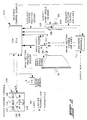
- FIG. 1 is a schematic illustration of a partially automated vehicular mechanical transmission system advantageously utilizing the present invention.
- FIG. 2 is a schematic illustration of a partially automatic shift implementation system for a mechanical transmission system advantageously utilizing the present invention.
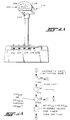
- FIG. 2A is an elevational view of an alternate driver control for the automated transmission system of FIG. 2.
- FIG. 3 is a schematic illustration of typical shift profiles for a heavy duty vehicular automated mechanical transmission.
- FIGS. 4A and 4B are schematic illustrations, in flowchart format, of the present invention.
- Certain terminology will be used in the following description for convenience in reference only and will not be limiting. The term "compound transmission" is used to designate a change speed or change gear transmission having a multiple forward speed main transmission section and a multiple speed auxiliary transmission section connected in series whereby the selected gear reduction in the main transmission section may be compounded by further selected gear reduction in the auxiliary transmission section. "Synchronized clutch assembly" and words of similar import shall designate a clutch assembly utilized to non-rotatably couple a selected gear to a shaft by means of a positive clutch in which attempted engagement of said clutch is prevented until the members of the clutch are at substantially synchronous rotation in a relatively large capacity friction means are utilized with the clutch members and are sufficient, upon initiation of a clutch engagement, to cause the clutch members and all members rotating therewith to rotate at substantially synchronous speed.
- The term "upshift" as used herein, shall mean the shifting from a lower speed gear ratio into a higher speed gear ratio. The term "downshift" as used herein, shall mean the shifting from a higher speed gear ratio to a lower speed gear ratio. The terms "low speed gear", "low gear" and/or "first gear" as used herein, shall all designate the gear ratio utilized for lowest forward speed operation in a transmission or transmission section, i.e., that set of gears having the highest ratio of reduction relative to the input shaft of the transmission.
- The term "automatic shift initiation" is intended to apply to initiation of fully automatic shifts as seen in above-mentioned U.S. Patent Nos. 4,361,060 and 5,109,721, to initiation of fully automatic shifts in only selected groupings of ratios as seen in above-mentioned U.S. Patent No. 4,722,248 and to automatic preselection of a shift and/or issuing of a shift prompt as seen in above-mentioned U.S. Patent Nos. 5,053,961 and 5,053,962.
- Signals indicative of engine speed will include signals from engine speed sensors, signals from input shaft speed sensors, and singles such as output shaft and gear ratio signals which may be used to calculate (ES=OS*GR) and/or estimate engine speed.
- Referring to Figure 1, a range
type compound transmission 10 of the type partially automated by the semi-automatic mechanical transmission system of the present invention is illustrated.Compound transmission 10 comprises a multiple speedmain transmission section 12 connected in series with a range typeauxiliary section 14.Transmission 10 is housed within a housing H and includes aninput shaft 16 driven by a prime mover such as diesel engine E through a selectively disengaged, normally engaged friction master clutch C having an input or drivingportion 18 drivingly connected to theengine crankshaft 20 and a drivenportion 22 rotatably fixed to thetransmission input shaft 16. - The engine E is fuel throttle controlled by a manually or automatically controlled throttle device (not shown) and the master clutch C is manually controlled by a clutch pedal (not shown) or automatically controlled by a clutch actuator, or the like. An input shaft brake B, usually operated by overtravel of the clutch pedal, is preferably provided to provide quicker upshifting as is well known in the prior art.
- Transmissions similar to compound
mechanical transmission 10 are well known in the prior art and may be appreciated by reference to U.S. Pat. Nos. 3,105,395; 3,283,613; 4,735,109 and 4,754,665, the disclosures of which are incorporated herein by reference. Asensor 11 may be provided for sensing the rotational speed of the engine and providing a signal indicative thereof. - In
main transmission section 12, theinput shaft 16 carries aninput gear 24 for simultaneously driving a plurality of substantiallyidentical countershaft assemblies mainshaft 28 which is generally coaxially aligned with theinput shaft 16. Each of the countershaft assemblies comprises acountershaft 30 supported bybearings countershaft gears mainshaft gears mainshaft 28 and are selectively clutchable, one at a time, to themainshaft 28 for rotation therewith by slidingclutch collars Clutch collar 60 may also be utilized toclutch input gear 24 to mainshaft 28 to provide a direct drive relationship betweeninput shaft 16 and mainshaft 28. - Typically,
clutch collars shift housing assembly 70, as well known in the prior art.Clutch collars - Shift housing or
actuator 70 may be actuated by electric motors or by compressed fluid, such as compressed air, and is of the type automatically controllable by a control unit as may be seen by reference to U.S. Patent Nos. 4,445,393; 4,555,959; 4,361,060; 4,676,115; 4,873,881 and 4,899,607, the disclosures of which are incorporated herein by reference. - Mainshaft gear 58 is the reverse gear and is in continuous meshing engagement with
countershaft gears 48 by means of conventional intermediate idler gears (not shown). It should also be noted that whilemain transmission section 12 does provide five selectable forward speed ratios, the lowest forward speed ratio, namely that provided by drivingly connectingmainshaft drive gear 56 tomainshaft 28, is often of such a high gear reduction it has to be considered a low or "creeper" gear which is utilized only for starting of a vehicle under severe conditions and is not usually utilized in the high transmission range. Accordingly, whilemain transmission section 12 does provide five forward speeds, it is usually referred to as a "four plus one" main section as only four of the forward speeds are compounded by the auxiliaryrange transmission section 14 utilized therewith. Similar transmissions provide 10, 13, 16 or 18 forward speeds as may be seen by reference to U.S. Patent Nos. 4,754,665 and 4,974,468. -
Jaw clutches actuator 70. As is well known, only one of theclutches - Auxiliary
transmission range section 14 includes two substantially identicalauxiliary countershaft assemblies auxiliary countershaft 76 supported bybearings section countershaft gears Auxiliary countershaft gears 82 are constantly meshed with and support range/output gear 86 while auxiliarysection countershaft gears 84 are constantly meshed withoutput gear 88 which is fixed totransmission output shaft 90. - A two-position synchronized
jaw clutch assembly 92, which is axially positioned by means of a shift fork (not shown) and the range section shiftingactuator assembly 96, is provided for clutching eithergear 86 tomainshaft 28 for low range operation orgear 88 to mainshaft 28 for direct or high range operation of thecompound transmission 10. -
Range section actuator 96 may be of the type illustrated in U.S. Patent Nos. 3,648,546; 4,440,037 and 4,614,126, the disclosures of which are hereby incorporated by reference. - Although the range type
auxiliary section 14 is illustrated as a two-speed section utilizing spur or helical type gearing, it is understood that the present invention is also applicable to simple transmissions and to range type transmissions utilizing combined splitter/range type auxiliary sections, having three or more selectable range ratios and/or utilizing planetary type gearing. Also, any one or more ofclutches transmission sections 12 and/or 14 may be of the single countershift type. Further, the present invention is also applicable to automated transmissions utilizing friction clutches rather than jaw clutches to engage selected ratios. - The semi-automatic shift
implementation control system 104 for a mechanical transmission system of the present invention is schematically illustrated in Figure 2.Control system 104, in addition to themechanical transmission system 10 described above, includes anelectronic control unit 106, preferably microprocessor based, for receiving input signals from theengine speed sensor 11, inputshaft speed sensor 98, from the output shaft speed sensor 100 (or, alternatively, the mainshaft speed sensor 102) and from thedriver control console 108. TheECU 106 may also receive inputs from an auxiliarysection position sensor 110. - The ECU is effective to process the inputs in accordance with predetermined logic rules to issue issue command output signals to a transmission operator, such as
solenoid manifold 112 which controls themainsection section actuator 70 and theauxiliary section actuator 96, and to thedriver control console 108. ECU's of this type are well known in the prior art as may be seen by reference to U.S. Patent 4,595,986, the disclosure of which is incorporated herein by reference. - The driver control and display console allows the operator to select a manual or hold mode of operation for manually selecting a shift in a given direction (i.e. upshifts or downshifts) or to neutral from the currently engaged ratio, or to select a semi-automatic preselect mode of operation, and provides a display for informing the operator of the current mode of operation (automatic or manual preselection of shifting), the current transmission operation condition (forward, reverse or neutral) and of any ratio change or shift (upshift, downshift or shift to neutral) which has been preselected but not yet implemented.
-
Console 108 includes threeindicator lights transmission 10 is in a forward drive, neutral or reverse drive, respectively, condition. The console also includes three selectively lightedpushbuttons pushbutton 126 allows selection of a shift into neutral. - A selection made by depressing or pushing any one of
buttons buttons 120, 124 and 126) by redepressing the buttons. As an alternative, multiple depressions ofbuttons 120 and 124 may be used as commands for skip shifts. Of course, the buttons and lighted buttons can be replaced by other selection means, such as a toggle switch and/or a toggle switch and light or other indicia member. A separate button or switch for selection of reverse may be provided or reverse may be selected as a downshift from neutral. Also, neutral may be selected as an upshift from reverse or as a downshift from low. - In operation, to select upshifts and downshifts manually, the operator will depress either button 120 or
button 124 as appropriate. The selected button will then be lighted until the selected shift is implemented or until the selection is cancelled. - An alternate to the
control console 108 is illustrated in Figure 2A. Briefly, amode selector 210 is utilized to select reverse (R) 212, neutral (N) 214, drive (automatic) (D) 216, hold (manual) (H) 218 and low (L) 220. The mode selector includes ahandle 222 having a reverseinterlock release button 224 andupshift 226 and downshift 228 selection buttons. The function ofmode selector 210 is substantially identical to console 108 described above. - To implement a selected shift, the manifold 112 is preselected to cause
actuator 70 to be biased to shiftmain transmission section 12 into neutral. This is accomplished by the operator causing a torque break or reversal by manually momentarily decreasing and/or increasing the supply of fuel to the engine and/or manually disengaging the master clutch C. As the transmission is shifted into neutral, and neutral is verified by the ECU (neutral sensed for a period of time such as 1.5 seconds), the neutralcondition indicia button 116 is lighted. If the selected shift is a compound shift, i.e. a shift of both themain section 12 and of therange section 14, such as a shift- from 4th to 5th speeds as seen in Figure 1A, the ECU will issue issue command output signals tomanifold 112 to cause theauxiliary section actuator 96 to complete the range shift after neutral is sensed in the front box. - When the range auxiliary section is engaged in the proper ratio, the ECU will calculate or otherwise determine, and continue to update, an enabling range or band of input shaft speeds, based upon sensed output shaft (vehicle) speed and the ratio to be engaged, which will result in an acceptably synchronous engagement of the ratio to be engaged. As the operator, or a control unit, by throttle manipulation and/or use of the input shaft brake, causes the input shaft speed to fall within the acceptable range, the
ECU 106 will issue issue command output signals tomanifold 112 to causeactuator 70 to engage the mainsection ratio to be engaged. Preferably, the actuator will respond very quickly not requiring the operator to maintain the input shaft speed within the acceptable range for an extended period of time. To select a shift into transmission neutral,selection button 126 is pushed. Indicating light 116 will flash until the ECU confirms that neutral is obtained at which time the light 116 will assume a continuously lighted condition while the transmission remains in neutral. - In the control algorithms, the issuing of command output signals for engagement of a target gear is dependent upon the transmission (i.e. the input shaft) being manually brought to within an acceptable synchronous point. This synchronous point is usually a range of RPMs (error band) centered about an error of zero RPM (i.e. when input shaft speed equals the product of output shaft speed times the numerical value of the target gear ratio, IS = OS*GRT). When the control electronics sense that the input shaft speed falls within the error band it will fire the solenoid of
manifold 112 that will cause the target gear to be engaged. The error bands are selected to give the best shift quality for each gear ratio. These error bands are usually stored in software in the form of tables that are indexed as a function of target gear. When these tables are set up for best shift quality the bands must be made small to minimize "clunking" as the target gear is engaged. With small error bands it is more difficult for the driver to bring the transmission to the correct synchronous point and he may miss it altogether and end up in neutral. - Above-mentioned U.S. Patent No. 5,063,511 provided a missed shift recovery algorithm that will access a second set of tables a short time after neutral has been sensed (one second). In a normal shift, one second is ample time for the driver to have brought the transmission to the synchronous point. If the neutral state has existed for more than the allowed time the algorithms will assume the driver has missed the shift and call for the new set of tables. This second set of tables will open the error bands to allow for a harsher shift which enhances the probability that the driver's efforts will result in engagement of the target gear instead of remaining in a neutral state.
- In the automatic preselection mode of operation, selected by use of lighted
pushbutton 122, or by movingselector 210 to the "D" position, the ECU will, based upon stored logic rules, currently engaged ratio (which may be position sensed and/or calculated by comparing input shaft to output shaft speed) and output shaft speed, determine if an upshift or a downshift is required and preselect same. The operator is informed that an upshift or downshift is preselected and will be semi-automatically implemented by a command output signal fromECU 106 causing either lighted pushbutton 120 or lightedpushbutton 124 to flash and/or an audible shift alert signal. The operator may initiate semi-automatic implementation of the automatically preselected shift as indicated above or may cancel the automatic mode by depression ofpushbutton 122. - As is very well known, in a heavy duty multiple speed mechanical transmission having 9, 10, 12, 13, 16 19 or 20 selectable forward gear ratios (GR), for many vehicle speeds, 3, 4 or 5 of the ratios are permissibly engageable (i.e. at current vehicle speed, and at master clutch (C) lockup, the calculated engine speed (ES=GR*OS) will be above a minimum value (ESMIN) and below a maximum value (ESMAX). The minimum value (ESMIN) is usually about the stall speed of the engine while the maximum value (ESMAX) is slightly below a destructive speed. For a typical vehicular heavy duty diesel engine, the minimum speed is usually about 600 RPM, the maximum speed is about 2200 RPM and the desirable range is about 1300-1600 RPM.
- In the automatic or drive mode of operation of
system 10, shifts are automatically initiated, in this transmission system embodiment preselected, in accordance with shift profiles as is well known in the prior art. Typical shift profiles are schematically illustrated in Figure 3 and are usually determined in theECU 106 by calculation and/or look-up table methods. - Briefly, for a given set of vehicle conditions, such as throttle pedal position, a profile for engine speeds at which upshifts and downshifts should be automatically implemented is generated. Referring to Figure 3,
lines area 244 between the upshift and downshift profiles requires no action, operation inarea 246 to the right of upshift profiles 240 requires initiation of an upshift and operation inarea 248 to the left ofdownshift profile 242 requires initiation of a downshift. As is also well known, to provide an anti-hunting feature, the upshift profile may be temporarily offset to the right after a downshift and/or the downshift profile may be temporarily offset to left after an upshift.Lines 250 and 252, respectively, represent the anti-hunt offset upshift and downshift, respectively, profiles. As may be seen, theoffsets 254 may be by 150 or more RPM. Typically, the shift profiles will return to the default values from the offset values thereof upon the passage of time and/or upon obtaining a certain vehicle or engine speed. - The control of the present invention allows the vehicle operator or driver to manually modify vehicle performance, while operating in the automatic or drive mode of
transmission system 10 by manually causing the engine speeds at which shifts are automatically initiated to be increased or decreased, within limits. - Assuming off-set profile 252 represents the minimum downshift engine speeds (ESMIN DS) and off-set
profile 250 represents the maximum upshift engine speeds (ESMAX US),lines mechanical transmission 10. - In the drive or automatic shift initiation mode of operation, the vehicle driver may use the upshift and downshift
buttons upshift button 226 while in the drive mode will signal a selection of advanced upshifts, and delayed downshifts, causing the ECU to temporarily decrease the engine speeds (ESUS and ESDS) at which upshifts and downshifts will be automatically initiated. By way of example, this can result in moving fromshift profiles 240 and/or 242 to shiftprofiles 256 and/or 252 and/or fromshift profiles 250 and/or 258 to shiftprofiles 240 and/or 258 to shiftprofiles 240 and/or 242. Conversely, manual operation of thedownshift button 228 while in the drive mode will signal a driver request for temporarily advanced downshifts and delayed upshifts, causing the ECU to temporarily increase the engine speeds (ESUS and ESDS) at which upshifts will be automatically initiated. By way of example, this can result in shift fromdownshift profile 252 or 242 to downshiftprofile upshift profile profile - The present invention is illustrated in flowchart format in Figure 4.
- As with the automatic shift profile offsets discussed above, it is preferable that the manually selected shift profile offsets be only temporary and that, after the occurrence of defined preconditions, such as the passage of time, the completion of a shift and/or engine or vehicle speed obtained a reference value, the shift point engine speeds return to the default value (240/242) thereof.
- It may be seen that the present invention allows the operator of a vehicle equipped with an automated transmission and operating in an automatic shift initiation mode to temporarily advance or delay automatic shift initiation to modify vehicle performance for then existing conditions. For example, if a vehicle driver sees a steep grade ahead, he may push the "downshift"
button 228 to delay automatic upshifts and/or advance automatic downshifts. - Although the present invention has been described with a certain degree of particularity, it is understood that various changes to form and detail may be made without departing from the spirit and the scope of the invention as hereinafter claimed.
Claims (27)
- An automated vehicular transmission system comprising a fuel throttle controlled engine (E), a multiple speed change gear transmission (10) having an input shaft (16) and an output shaft (90), a nonpositive coupling drivingly interposed between the engine and the transmission input shaft, a first sensor (11/98/100) for providing a first input signal indicative of engine rotation speed (ES/IS/OS*GR), a mode selector (210) for manual selection of transmission operating modes, including a selectable automatic shift initiation mode, and for providing a second input signal indicative of the selected transmission mode, a control unit (106) for receiving said input signals and for processing same according to predetermined logic rules to issue issue command output signals and actuators (112, 70, 96) responsive to said output signals for controlling shifting of said transmission,
said system in the automatic shift initiation mode effective to automatically initiate upshifts if sensed engine speed (ESS) is greater than an upshift engine speed value (ESUS) and to automatically initiate downshifts if sensed engine speed is less than a downshift engine speed value (ESDS), said upshift and downshift engine speed values having maximum (ESMAX US, ESMAX DS) and minimum (ESMIN US and ESMIN DS) values thereof,
said system characterized by:
a first preference selector (226) for manual selection of advanced automatic upshift initiation and for providing a third input signal indicative thereof, said control unit responsive to manual selection of advanced automatic upshift initiation to decrease the value of the upshift engine speed value but not below said minimum value (ESMIN US) thereof. - The system of claim 1 further characterized by a second preference selector (228) for manual selection of advanced automatic downshift initiation and for providing a fourth input signal indicative thereof, said control unit responsive to manual selection of advanced automatic downshift initiation to increase the value of the downshift engine speed value but not above said maximum value (ESMAX DS) thereof.
- The system of claims 1 or 2 further characterized by said control unit responsive to manual selection of advanced automatic upshift initiation to also decrease the value of the downshift engine speed value but not below the said minimum value (ESMIN DS) thereof.
- The system of claim 2 further characterized by said control unit is responsive to manual selection of advanced automatic upshift initiation to also decrease the value of the downshift engine speed value but not below the said minimum value (ESMIN DS) thereof and is responsive to manual selection of advanced automatic downshift initiation to also increase the value of the upshift engine speed value but above said maximum value (ESMAX US) thereof.
- An automated vehicular transmission system comprising a fuel throttle controlled engine (E), a multiple speed change gear [mech] transmission (10) having an input shaft (16) and an output shaft (90), a nonpositive coupling [clutch] drivingly interposed between the engine and the transmission input shaft, a first sensor (11/98/100) for providing a first input signal indicative of engine rotation speed (ES/IS OS*GR), a mode selector (210) for manual selection of transmission operating modes, including a selectable automatic shift initiation mode, and for providing a second input signal indicative of the selected transmission mode, a central processing unit (106) for receiving said input signals and for processing same according to predetermined logic rules to issue issue command output signals and actuators (112, 70, 96) responsive to said output signals for controlling shifting of said transmission,
said system in the automatic shift initiation mode effective to automatically initiate upshifts if sensed engine speed (ESS) is greater than an upshift engine speed value (ESUS) and to automatically initiate downshifts if sensed engine speed is less than a downshift engine speed value (ESDS), said upshift and downshift engine speed values having maximum (ESMAX US, ESMAX DS) and minimum (ESMIN US and ESMIN DS) values thereof,
said system characterized by:
a second preference selector (228) for manual selection of advanced automatic downshift initiation and for providing a fourth input signal indicative thereof, said control unit responsive to manual selection of advanced automatic downshift initiation to increase the value of the downshift engine speed value but not below said maximum value (ESMAX DS) thereof. - The system of claim 5 further characterized by said control unit is responsive to manual selection of advanced automatic downshift initiation to also increase the value of the upshift engine speed value but above said maximum value (ESMAX DS) thereof.
- An automated vehicular transmission system comprising a fuel throttle controlled engine (E), a multiple speed change gear [mech] transmission (10) having an input shaft (16) and an output shaft (90), a nonpositive coupling [clutch] drivingly interposed between the engine and the transmission input shaft, a first sensor (11/98/100) for providing a first input signal indicative of engine rotation speed (ES/IS OS*GR), a mode selector (210) for manual selection of transmission operating modes, including a selectable automatic shift initiation mode, and for providing a second input signal indicative of the selected transmission mode, a central processing unit (106) for receiving said input signals and for processing same according to predetermined logic rules to issue issue command output signals and actuators (112, 70, 96) responsive to said output signals for controlling shifting of said transmission,
said system in the automatic shift initiation mode effective to automatically initiate upshifts if sensed engine speed (ESS) is greater than an upshift engine speed value (ESUS) and to automatically initiate downshifts if sensed engine speed is less than a downshift engine speed value (ESDS), said upshift and downshift engine speed values having maximum (ESMAX US, ESMAX DS) and minimum (ESMIN US and ESMIN DS) values thereof,
said system characterized by:
a first preference selector (226) for manual selection of delayed automatic downshift initiation and for providing a third input signal indicative thereof, said control unit responsive to manual selection of delayed automatic downshift initiation to decrease the value of the downshift engine speed value but not below said minimum value (ESMIN DS) thereof. - The system of claim 7 further characterized by a second preference selector (228) for manual selection of delayed automatic upshift initiation and for providing a fourth input signal indicative thereof, said control unit responsive to manual selection of delayed automatic upshift initiation to increase the value of the upshift engine speed value but not above said maximum value (ESMAX US) thereof.
- An automated vehicular transmission system comprising a fuel throttle controlled engine (E), a multiple speed change gear [mech] transmission (10) having an input shaft (16) and an output shaft (90), a nonpositive coupling [clutch] drivingly interposed between the engine and the transmission input shaft, a first sensor (11/98/100) for providing a first input signal indicative of engine rotation speed (ES/IS OS*GR), a mode selector (210) for manual selection of transmission operating modes, including a selectable automatic shift initiation mode, and for providing a second input signal indicative of the selected transmission mode, a central processing unit (106) for receiving said input signals and for processing same according to predetermined logic rules to issue issue command output signals and actuators (112, 70, 96) responsive to said output signals for controlling shifting of said transmission,
said system in the automatic shift initiation mode effective to automatically initiate upshifts if sensed engine speed (ESS) is greater than an upshift engine speed value (ESUS) and to automatically initiate downshifts if sensed engine speed is less than a downshift engine speed value (ESDS), said upshift and downshift engine speed values having maximum (ESMAX US, ESMAX DS) and minimum (ESMIN US and ESMIN DS) values thereof,
said system characterized by:
a second preference selector (228) for manual selection of delayed automatic upshift initiation and for providing a fourth input signal indicative thereof, said control unit responsive to manual selection of delayed automatic upshift initiation to increase the value of the upshift engine speed value but not above said maximum value (ESMAX US) thereof. - The system of claims 1, 5, 7 or 9 wherein said transmissions are mechanical transmissions.
- The system of claims 2, 4, 5, 6, 8 or 9 wherein said engine speed values are increased by about 150 RPM.
- The system of claims 1, 2, 3, 4, 6, 7 or 8 wherein said engine speed values are decreased by about 150 RPM.
- The system of claims 6, 8 or 9 wherein said controller is effective to establish a default upshift engine speed value (240) intermediate said minimum and maximum values thereof and said system is effective to increase said upshift engine speed value from said intermediate to said maximum value thereof and from minimum value to said default value thereof.
- The system of claim 4 wherein said controller is effective to establish a default upshift engine speed value (240) intermediate said minimum and maximum values thereof and said system is effective to increase said upshift engine speed value from said intermediate to said maximum value thereof and from minimum value to said default value thereof.
- The system of claim 14 wherein said system is effective to decrease said upshift engine speed value from said default value to said minimum value thereof and from said maximum value to said default value thereof.
- The system of claims 2, 5 or 6 wherein said controller is effective to establish a default downshift engine speed value (242) intermediate said minimum and maximum values thereof and said system is effective to increase said downshift engine speed value from said default value to said maximum value thereof and from minimum value to said default value thereof.
- The system of claim 4 wherein said controller is effective to establish a default downshift engine speed value (242) intermediate said minimum and maximum values thereof and said system is effective to increase said downshift engine speed value from said default value to said maximum value thereof and from minimum value to said default value thereof.
- The system of claim 17 wherein said system is effective to decrease said downshift engine speed value from said default value to said minimum value thereof and from said maximum value to said default value thereof.
- The system of claim 13 wherein said maximum upshift engine value is equal to the last shift downshift offset value thereof.
- An automated vehicular transmission system comprising a fuel throttle controlled engine (E), a multiple speed change gear mechanical transmission (10) having an input shaft (16) and an output shaft (90), a friction clutch drivingly interposed between the engine and the transmission input shaft, a first sensor (11/98/100) for providing a first input signal indicative of engine rotation speed (ES/IS/OS*GR), a mode selector (210) for manual selection of transmission operating modes, including a manual shift initiation mode (H) and an automatic shift initiation mode (D), and for providing a second input signal indicative of the selected transmission mode, an upshift/downshift selector (226/228) for selecting manual initiation of upshifts and downshifts, respectively, in the manual shift initiation mode and for providing third and fourth input signals, respectively indicative of the direction of manually selected shift, a central processing unit (106) for receiving said input signals and for processing same according to predetermined logic rules to issue issue command output signals and actuators (112, 70, 96) responsive to said output signals for controlling shifting of said transmission,
said system in the automatic shift initiation mode effective to automatically initiate upshifts if sensed engine speed (ESS) is greater than an upshift engine speed value (ESUS) and to automatically initiate downshifts if sensed engine speed is less than a downshift engine speed value (ESDS), said upshift and downshift engine speed values having maximum (ESMAX US, ESMAX DS) and minimum (ESMIN US and ESMIN DS) values thereof,
said system characterized by:
means effective in said automatic shift initiation mode responsive to manual selection of an upshift initiation to decrease the value of the upshift and downshift engine speed values but not below said minimum values (ESMIN US and ESMIN DS) thereof and responsive to manual selection of a downshift initiation to increase the values of the upshift and downshift engine speed values but not above said maximum values (ESMAX US) and (ESMAX DS) thereof. - The system of claim 20 wherein said engine speed values are increased by about 150 RPM.
- The system of claim 20 wherein said engine speed values are decreased by about 150 RPM.
- The system of claim 20 wherein said controller is effective to establish a default upshift engine speed value (240) intermediate said minimum and maximum values thereof and said system is effective to increase said upshift engine speed value from said default value to said maximum value thereof and from minimum value to said default value thereof.
- The system of claim 23 wherein said system is effective to decrease said upshift engine speed value from said default value to said minimum value thereof and from said maximum value to said default value thereof.
- The system of claims 23 or 24 wherein, after a predetermined period of time after receipt of said third or fourth input signal, said engine speed values will assume said default values thereof.
- The system of claims 23 or 24 wherein, if after engine speed equals a reference value after receipt of said third or fourth input signal, said engine speed values will assume said default values thereof.
- The system of claim 20 wherein said system, in the manual shift initiation mode, includes means responsive to (i) a selection of a shift from a currently engaged ratio or from neutral into a selected target ratio and (ii) confirmation of a transmission neutral condition for (i) sensing and storing the then current vehicle speed as an initial vehicle speed VSi (ii) and thereafter sensing substantial synchronization of the transmission and (iii) thereafter for issuing command output signals to said actuator to enable the transmission to be shifted into the selected target ratio; said means sensing substantial synchronization of said transmission by comparing said first signal to a reference range determined as a function of said selected target ratio and said second signal.
Applications Claiming Priority (2)
| Application Number | Priority Date | Filing Date | Title |
|---|---|---|---|
| US08/126,843 US5406861A (en) | 1993-09-22 | 1993-09-22 | Manual modification of automatic mode shift points |
| US126843 | 1993-09-22 |
Publications (2)
| Publication Number | Publication Date |
|---|---|
| EP0644360A1 true EP0644360A1 (en) | 1995-03-22 |
| EP0644360B1 EP0644360B1 (en) | 1997-08-20 |
Family
ID=22426972
Family Applications (1)
| Application Number | Title | Priority Date | Filing Date |
|---|---|---|---|
| EP94306786A Expired - Lifetime EP0644360B1 (en) | 1993-09-22 | 1994-09-16 | Manual modification of automatic mode shift points |
Country Status (10)
| Country | Link |
|---|---|
| US (1) | US5406861A (en) |
| EP (1) | EP0644360B1 (en) |
| JP (1) | JPH07167289A (en) |
| KR (1) | KR100299016B1 (en) |
| AT (1) | ATE157151T1 (en) |
| AU (1) | AU672524B2 (en) |
| BR (1) | BR9403613A (en) |
| CA (1) | CA2132562C (en) |
| DE (1) | DE69405066T2 (en) |
| ES (1) | ES2107754T3 (en) |
Cited By (7)
| Publication number | Priority date | Publication date | Assignee | Title |
|---|---|---|---|---|
| DE19747262A1 (en) * | 1997-10-25 | 1999-05-06 | Deere & Co | Transmission control and control method for a powershift transmission |
| DE10003140C1 (en) * | 2000-01-26 | 2001-08-09 | Daimler Chrysler Ag | Mode selector for vehicle transmissions |
| GB2423123A (en) * | 2005-02-11 | 2006-08-16 | Agco Sa | Transmission controller with control dial having two speed matching zones |
| GB2446958A (en) * | 2005-02-11 | 2008-08-27 | Agco Sa | Transmission speed change gearbox operating automatically in a field working mode |
| WO2008150201A1 (en) | 2007-06-08 | 2008-12-11 | Volvo Lastvagnar Ab | A method for adjustment of an automatically selected gear shifting rotational speed limit in a vehicle |
| EP1925857A3 (en) * | 2006-11-27 | 2011-08-03 | ZF Friedrichshafen AG | Method and apparatus for changing shift schedulling modes of automated mechanical transmission |
| US9079575B2 (en) | 2012-11-14 | 2015-07-14 | Caterpillar Inc. | Machine powertrain control system and method |
Families Citing this family (24)
| Publication number | Priority date | Publication date | Assignee | Title |
|---|---|---|---|---|
| GB9525055D0 (en) * | 1995-12-07 | 1996-02-07 | Eaton Corp | Controled for automated mechanical transmission system |
| US5678453A (en) * | 1996-02-01 | 1997-10-21 | Eaton Corporation | Start ratio selection for vehicular automated transmissions |
| GB9617956D0 (en) * | 1996-08-28 | 1996-10-09 | Eaton Corp | Downshift control method/system for vehicular automated mechanical transmission |
| US5846161A (en) * | 1996-12-03 | 1998-12-08 | Caterpillar Inc. | Control system for an automatic transmission having shift points based on part throttle positions which are used when engine speed is lowered below an adjustable minimum engine speed setting |
| US5809835A (en) * | 1997-01-21 | 1998-09-22 | Ford Global Technologies, Inc. | Manual transmission shift lever |
| GB9721823D0 (en) | 1997-10-16 | 1997-12-17 | Eaton Corp | Shift into optimal engine braking control system and method |
| US6285941B1 (en) | 1998-08-31 | 2001-09-04 | Eaton Corporation | Method/system for controlling shifting in an automated mechanical transmission system |
| US6157886A (en) * | 1998-08-31 | 2000-12-05 | Eaton Corporation | Method/system for controlling upshifting in an automated mechanical transmission system |
| US6233512B1 (en) | 1998-09-08 | 2001-05-15 | Eaton Corporation | Method/system for controlling upshifting in an automated mechanical transmission system |
| US6085606A (en) * | 1998-11-03 | 2000-07-11 | Eaton Corporation | Mechanical transmission with reduced ratio steps in upper transmission ratios |
| GB9828452D0 (en) | 1998-12-24 | 1999-02-17 | Eaton Corp | Automated transmission downshift control |
| US6042507A (en) * | 1999-04-22 | 2000-03-28 | Eaton Corporation | Torque converter lockup control |
| US6178366B1 (en) | 1999-07-19 | 2001-01-23 | Eaton Corporation | Method/system for initiating automatic upshifting in an automated mechanical transmission system |
| US6480774B1 (en) | 1999-07-23 | 2002-11-12 | Eaton Corporation | Convertible transmission system |
| US6658339B1 (en) | 1999-11-26 | 2003-12-02 | Eaton Corporation | Driver-programmable driving mode system for automatic transmissions |
| JP2001213201A (en) * | 1999-12-17 | 2001-08-07 | Getrag Getriebe & Zahnradfab Hermann Hagenmeyer Gmbh & Co | Automatic drive mechanism train for automobile and method for controlling drive mechanism train |
| EP1355209A1 (en) | 2002-04-18 | 2003-10-22 | Ford Global Technologies, LLC | Vehicle control system |
| CA2558890C (en) * | 2004-03-16 | 2009-03-03 | The Dial Corporation | Applicator device |
| JP4188359B2 (en) * | 2005-10-31 | 2008-11-26 | 本田技研工業株式会社 | Shift control device for automatic transmission |
| US7747372B2 (en) * | 2007-07-03 | 2010-06-29 | Toyota Motor Engineering & Manufacturing North America, Inc. | Systems and methods for user control of vehicular transmission shift points |
| US7859394B1 (en) * | 2008-01-23 | 2010-12-28 | Fes Llc | Shift light system and method |
| DE102009055833A1 (en) * | 2009-11-26 | 2011-06-01 | GM Global Technology Operations LLC, ( n. d. Ges. d. Staates Delaware ), Detroit | Method for controlling a switching operation of an automatic transmission |
| JP5244169B2 (en) * | 2010-12-24 | 2013-07-24 | 富士重工業株式会社 | Vehicle driving force control device |
| DE102014017175B4 (en) * | 2014-11-20 | 2016-11-10 | Audi Ag | Method and device for operating a motor vehicle |
Citations (7)
| Publication number | Priority date | Publication date | Assignee | Title |
|---|---|---|---|---|
| GB2033981A (en) * | 1978-09-29 | 1980-05-29 | Borg Warner | Multi-ratio Gear Arrangement |
| GB2034422A (en) * | 1978-09-05 | 1980-06-04 | Nissan Motor | Speed-change control system for an automatic transmission |
| EP0171770A2 (en) * | 1984-08-10 | 1986-02-19 | Toyota Jidosha Kabushiki Kaisha | A method of controlling a transmission of a vehicle |
| WO1986005449A1 (en) * | 1985-03-23 | 1986-09-25 | Zahnradfabrik Friedrichshafen Ag | Control device for shifting step-by-step shift gears |
| DE3626100A1 (en) * | 1985-08-10 | 1987-02-19 | Zahnradfabrik Friedrichshafen | Gear change control for automatic gearbox |
| EP0310275A2 (en) * | 1987-09-28 | 1989-04-05 | SATURN CORPORATION (a Delaware corp.) | Failure mode shift pattern alteration for an electronically controlled transmission |
| EP0471102A1 (en) * | 1990-08-14 | 1992-02-19 | Siemens Aktiengesellschaft | Gear box control method for a motor vehicle |
Family Cites Families (13)
| Publication number | Priority date | Publication date | Assignee | Title |
|---|---|---|---|---|
| CA1123202A (en) * | 1978-10-04 | 1982-05-11 | William H. Pullen | Machine tool for dressing the end face of an engine cylinder liner |
| US4551802A (en) * | 1982-11-17 | 1985-11-05 | Eaton Corporation | Automatic transmission control method |
| JPS60116953A (en) * | 1983-11-28 | 1985-06-24 | Mazda Motor Corp | Control device of automatic speed changer |
| GB8418749D0 (en) * | 1984-07-23 | 1984-08-30 | Eaton Ltd | Semi-automatic transmission control |
| US5053962A (en) * | 1989-06-19 | 1991-10-01 | Eaton Corporation | Automatic shift preselection mode for mechanical transmission system with semi-automatic shift implementation |
| US5053961A (en) * | 1989-06-19 | 1991-10-01 | Eaton Corporation | Semi-automatic shift implementation for mechanical transmission system |
| US4991455A (en) * | 1989-12-01 | 1991-02-12 | Ford New Holland, Inc. | High speed deceleration of a power shift transmission |
| US5315514A (en) * | 1990-08-17 | 1994-05-24 | Eaton Corporation | Unexpected N logic for vehicular semi-automated mechanical transmissions |
| US5050079A (en) * | 1990-08-17 | 1991-09-17 | Eaton Corporation | Mode control for mechanical transmission system with semi-automatic shift implementation and manual and automatic shift preselection modes |
| US5109721A (en) * | 1991-05-09 | 1992-05-05 | Eaton Corporation | Range shifting only fault tolerance method/system |
| DE59106771D1 (en) * | 1991-05-17 | 1995-11-30 | Siemens Ag | Motor vehicle transmission with a control unit. |
| US5323669A (en) * | 1992-10-29 | 1994-06-28 | Eaton Corporation | Fault tolerant method of transmission gear selection |
| US5261288A (en) * | 1992-12-18 | 1993-11-16 | Eaton Corporation | Enhanced missed shift from neutral recovery for automated or semi-automated mechanical transmission system |
-
1993
- 1993-09-22 US US08/126,843 patent/US5406861A/en not_active Expired - Lifetime
-
1994
- 1994-09-16 DE DE69405066T patent/DE69405066T2/en not_active Expired - Fee Related
- 1994-09-16 ES ES94306786T patent/ES2107754T3/en not_active Expired - Lifetime
- 1994-09-16 EP EP94306786A patent/EP0644360B1/en not_active Expired - Lifetime
- 1994-09-16 AT AT94306786T patent/ATE157151T1/en not_active IP Right Cessation
- 1994-09-20 AU AU73097/94A patent/AU672524B2/en not_active Ceased
- 1994-09-21 CA CA002132562A patent/CA2132562C/en not_active Expired - Fee Related
- 1994-09-22 JP JP6254321A patent/JPH07167289A/en active Pending
- 1994-09-22 KR KR1019940023891A patent/KR100299016B1/en not_active IP Right Cessation
- 1994-09-22 BR BR9403613A patent/BR9403613A/en not_active IP Right Cessation
Patent Citations (7)
| Publication number | Priority date | Publication date | Assignee | Title |
|---|---|---|---|---|
| GB2034422A (en) * | 1978-09-05 | 1980-06-04 | Nissan Motor | Speed-change control system for an automatic transmission |
| GB2033981A (en) * | 1978-09-29 | 1980-05-29 | Borg Warner | Multi-ratio Gear Arrangement |
| EP0171770A2 (en) * | 1984-08-10 | 1986-02-19 | Toyota Jidosha Kabushiki Kaisha | A method of controlling a transmission of a vehicle |
| WO1986005449A1 (en) * | 1985-03-23 | 1986-09-25 | Zahnradfabrik Friedrichshafen Ag | Control device for shifting step-by-step shift gears |
| DE3626100A1 (en) * | 1985-08-10 | 1987-02-19 | Zahnradfabrik Friedrichshafen | Gear change control for automatic gearbox |
| EP0310275A2 (en) * | 1987-09-28 | 1989-04-05 | SATURN CORPORATION (a Delaware corp.) | Failure mode shift pattern alteration for an electronically controlled transmission |
| EP0471102A1 (en) * | 1990-08-14 | 1992-02-19 | Siemens Aktiengesellschaft | Gear box control method for a motor vehicle |
Non-Patent Citations (1)
| Title |
|---|
| PATENT ABSTRACTS OF JAPAN * |
Cited By (11)
| Publication number | Priority date | Publication date | Assignee | Title |
|---|---|---|---|---|
| DE19747262A1 (en) * | 1997-10-25 | 1999-05-06 | Deere & Co | Transmission control and control method for a powershift transmission |
| US6002976A (en) * | 1997-10-25 | 1999-12-14 | Deere & Company | Transmission shift control system and method |
| DE10003140C1 (en) * | 2000-01-26 | 2001-08-09 | Daimler Chrysler Ag | Mode selector for vehicle transmissions |
| GB2423123A (en) * | 2005-02-11 | 2006-08-16 | Agco Sa | Transmission controller with control dial having two speed matching zones |
| GB2446958A (en) * | 2005-02-11 | 2008-08-27 | Agco Sa | Transmission speed change gearbox operating automatically in a field working mode |
| GB2446958B (en) * | 2005-02-11 | 2009-09-02 | Agco Sa | Multi ratio transmission |
| US8311713B2 (en) | 2005-02-11 | 2012-11-13 | Agco Sa | Multi ratio transmission |
| EP1925857A3 (en) * | 2006-11-27 | 2011-08-03 | ZF Friedrichshafen AG | Method and apparatus for changing shift schedulling modes of automated mechanical transmission |
| WO2008150201A1 (en) | 2007-06-08 | 2008-12-11 | Volvo Lastvagnar Ab | A method for adjustment of an automatically selected gear shifting rotational speed limit in a vehicle |
| EP2156073A4 (en) * | 2007-06-08 | 2018-04-25 | Volvo Lastvagnar AB | A method for adjustment of an automatically selected gear shifting rotational speed limit in a vehicle |
| US9079575B2 (en) | 2012-11-14 | 2015-07-14 | Caterpillar Inc. | Machine powertrain control system and method |
Also Published As
| Publication number | Publication date |
|---|---|
| ATE157151T1 (en) | 1997-09-15 |
| CA2132562C (en) | 2000-09-19 |
| EP0644360B1 (en) | 1997-08-20 |
| US5406861A (en) | 1995-04-18 |
| DE69405066T2 (en) | 1998-03-19 |
| AU672524B2 (en) | 1996-10-03 |
| ES2107754T3 (en) | 1997-12-01 |
| AU7309794A (en) | 1995-04-06 |
| BR9403613A (en) | 1995-05-23 |
| JPH07167289A (en) | 1995-07-04 |
| KR950009029A (en) | 1995-04-21 |
| DE69405066D1 (en) | 1997-09-25 |
| KR100299016B1 (en) | 2001-12-01 |
| CA2132562A1 (en) | 1995-03-23 |
Similar Documents
| Publication | Publication Date | Title |
|---|---|---|
| US5406861A (en) | Manual modification of automatic mode shift points | |
| EP0404353B1 (en) | Semi-automatic shift implementation for mechanical transmission system | |
| CA2049242C (en) | Mode control for mechanical transmission system with semi-automatic shift implementation and manual and automatic shift preselection modes | |
| EP0651181B1 (en) | Driveline torque detection | |
| EP0404387B1 (en) | Automatic shift preselection made for mechanical transmission system with semi-automatic shift | |
| EP0449499B1 (en) | Start from stop control method | |
| US5053959A (en) | Control system and method for sensing and indicating neutral in a semi-automatic mechanical transmission system | |
| CA2049239C (en) | Unexpected n logic | |
| CA2020109C (en) | Shift implementation control system and method for mechanical transmission system | |
| US5761628A (en) | Start gear ratio control system and method utilizing the highest allowable start gear ratio | |
| EP0651180B1 (en) | Range section gearing recovery from not-engaged condition | |
| EP0413412B1 (en) | Semi-automatic shift implementation control system | |
| US5261288A (en) | Enhanced missed shift from neutral recovery for automated or semi-automated mechanical transmission system | |
| US5429559A (en) | Forced engagement logic | |
| EP0576156B1 (en) | Enhanced semi-automated mechanical transmission system | |
| EP0565257A1 (en) | Enhanced semi-automated mechanical transmission system |
Legal Events
| Date | Code | Title | Description |
|---|---|---|---|
| PUAI | Public reference made under article 153(3) epc to a published international application that has entered the european phase |
Free format text: ORIGINAL CODE: 0009012 |
|
| AK | Designated contracting states |
Kind code of ref document: A1 Designated state(s): AT DE ES FR GB IT NL SE |
|
| 17P | Request for examination filed |
Effective date: 19950518 |
|
| 17Q | First examination report despatched |
Effective date: 19960207 |
|
| GRAG | Despatch of communication of intention to grant |
Free format text: ORIGINAL CODE: EPIDOS AGRA |
|
| GRAH | Despatch of communication of intention to grant a patent |
Free format text: ORIGINAL CODE: EPIDOS IGRA |
|
| GRAH | Despatch of communication of intention to grant a patent |
Free format text: ORIGINAL CODE: EPIDOS IGRA |
|
| GRAA | (expected) grant |
Free format text: ORIGINAL CODE: 0009210 |
|
| AK | Designated contracting states |
Kind code of ref document: B1 Designated state(s): AT DE ES FR GB IT NL SE |
|
| REF | Corresponds to: |
Ref document number: 157151 Country of ref document: AT Date of ref document: 19970915 Kind code of ref document: T |
|
| REF | Corresponds to: |
Ref document number: 69405066 Country of ref document: DE Date of ref document: 19970925 |
|
| ET | Fr: translation filed | ||
| ITF | It: translation for a ep patent filed |
Owner name: ING. C. GREGORJ S.P.A. |
|
| REG | Reference to a national code |
Ref country code: ES Ref legal event code: FG2A Ref document number: 2107754 Country of ref document: ES Kind code of ref document: T3 |
|
| PLBE | No opposition filed within time limit |
Free format text: ORIGINAL CODE: 0009261 |
|
| STAA | Information on the status of an ep patent application or granted ep patent |
Free format text: STATUS: NO OPPOSITION FILED WITHIN TIME LIMIT |
|
| 26N | No opposition filed | ||
| REG | Reference to a national code |
Ref country code: GB Ref legal event code: IF02 |
|
| PGFP | Annual fee paid to national office [announced via postgrant information from national office to epo] |
Ref country code: AT Payment date: 20050701 Year of fee payment: 12 |
|
| PGFP | Annual fee paid to national office [announced via postgrant information from national office to epo] |
Ref country code: NL Payment date: 20050808 Year of fee payment: 12 |
|
| PGFP | Annual fee paid to national office [announced via postgrant information from national office to epo] |
Ref country code: FR Payment date: 20050902 Year of fee payment: 12 |
|
| PGFP | Annual fee paid to national office [announced via postgrant information from national office to epo] |
Ref country code: ES Payment date: 20050919 Year of fee payment: 12 |
|
| PG25 | Lapsed in a contracting state [announced via postgrant information from national office to epo] |
Ref country code: AT Free format text: LAPSE BECAUSE OF NON-PAYMENT OF DUE FEES Effective date: 20060916 |
|
| PGFP | Annual fee paid to national office [announced via postgrant information from national office to epo] |
Ref country code: IT Payment date: 20060930 Year of fee payment: 13 |
|
| PG25 | Lapsed in a contracting state [announced via postgrant information from national office to epo] |
Ref country code: NL Free format text: LAPSE BECAUSE OF NON-PAYMENT OF DUE FEES Effective date: 20070401 |
|
| NLV4 | Nl: lapsed or anulled due to non-payment of the annual fee |
Effective date: 20070401 |
|
| REG | Reference to a national code |
Ref country code: FR Ref legal event code: ST Effective date: 20070531 |
|
| REG | Reference to a national code |
Ref country code: ES Ref legal event code: FD2A Effective date: 20060918 |
|
| PG25 | Lapsed in a contracting state [announced via postgrant information from national office to epo] |
Ref country code: ES Free format text: LAPSE BECAUSE OF NON-PAYMENT OF DUE FEES Effective date: 20060918 |
|
| PG25 | Lapsed in a contracting state [announced via postgrant information from national office to epo] |
Ref country code: FR Free format text: LAPSE BECAUSE OF NON-PAYMENT OF DUE FEES Effective date: 20061002 |
|
| PGFP | Annual fee paid to national office [announced via postgrant information from national office to epo] |
Ref country code: GB Payment date: 20080808 Year of fee payment: 15 |
|
| PGFP | Annual fee paid to national office [announced via postgrant information from national office to epo] |
Ref country code: DE Payment date: 20080930 Year of fee payment: 15 |
|
| PGFP | Annual fee paid to national office [announced via postgrant information from national office to epo] |
Ref country code: SE Payment date: 20080905 Year of fee payment: 15 |
|
| PG25 | Lapsed in a contracting state [announced via postgrant information from national office to epo] |
Ref country code: IT Free format text: LAPSE BECAUSE OF NON-PAYMENT OF DUE FEES Effective date: 20070916 |
|
| EUG | Se: european patent has lapsed | ||
| GBPC | Gb: european patent ceased through non-payment of renewal fee |
Effective date: 20090916 |
|
| PG25 | Lapsed in a contracting state [announced via postgrant information from national office to epo] |
Ref country code: DE Free format text: LAPSE BECAUSE OF NON-PAYMENT OF DUE FEES Effective date: 20100401 |
|
| PG25 | Lapsed in a contracting state [announced via postgrant information from national office to epo] |
Ref country code: GB Free format text: LAPSE BECAUSE OF NON-PAYMENT OF DUE FEES Effective date: 20090916 |
|
| PG25 | Lapsed in a contracting state [announced via postgrant information from national office to epo] |
Ref country code: SE Free format text: LAPSE BECAUSE OF NON-PAYMENT OF DUE FEES Effective date: 20090917 |