EP0643505A1 - Multirate frames for a branched star telecommunications network - Google Patents
Multirate frames for a branched star telecommunications network Download PDFInfo
- Publication number
- EP0643505A1 EP0643505A1 EP94401938A EP94401938A EP0643505A1 EP 0643505 A1 EP0643505 A1 EP 0643505A1 EP 94401938 A EP94401938 A EP 94401938A EP 94401938 A EP94401938 A EP 94401938A EP 0643505 A1 EP0643505 A1 EP 0643505A1
- Authority
- EP
- European Patent Office
- Prior art keywords
- terminal equipment
- data
- cells
- frame
- downlink
- Prior art date
- Legal status (The legal status is an assumption and is not a legal conclusion. Google has not performed a legal analysis and makes no representation as to the accuracy of the status listed.)
- Granted
Links
- 230000005540 biological transmission Effects 0.000 claims abstract description 39
- 238000004891 communication Methods 0.000 claims description 23
- 230000000630 rising effect Effects 0.000 claims description 6
- 230000002457 bidirectional effect Effects 0.000 claims description 4
- 230000000737 periodic effect Effects 0.000 claims description 3
- 230000001419 dependent effect Effects 0.000 claims 1
- 238000011144 upstream manufacturing Methods 0.000 claims 1
- 230000003287 optical effect Effects 0.000 abstract description 14
- 239000013307 optical fiber Substances 0.000 abstract description 13
- 230000002441 reversible effect Effects 0.000 abstract description 4
- 238000013459 approach Methods 0.000 description 11
- 238000000034 method Methods 0.000 description 6
- 230000001934 delay Effects 0.000 description 5
- 238000010586 diagram Methods 0.000 description 3
- 239000000835 fiber Substances 0.000 description 3
- IWYDHOAUDWTVEP-UHFFFAOYSA-N mandelic acid Chemical compound OC(=O)C(O)C1=CC=CC=C1 IWYDHOAUDWTVEP-UHFFFAOYSA-N 0.000 description 3
- 230000001360 synchronised effect Effects 0.000 description 3
- 238000012937 correction Methods 0.000 description 2
- 230000002123 temporal effect Effects 0.000 description 2
- 238000006677 Appel reaction Methods 0.000 description 1
- 230000001174 ascending effect Effects 0.000 description 1
- 230000015572 biosynthetic process Effects 0.000 description 1
- 239000000470 constituent Substances 0.000 description 1
- 230000003111 delayed effect Effects 0.000 description 1
- 239000012464 large buffer Substances 0.000 description 1
- 238000004519 manufacturing process Methods 0.000 description 1
- 230000010287 polarization Effects 0.000 description 1
- 230000001629 suppression Effects 0.000 description 1
- 238000012546 transfer Methods 0.000 description 1
Images

Classifications
-
- H—ELECTRICITY
- H04—ELECTRIC COMMUNICATION TECHNIQUE
- H04J—MULTIPLEX COMMUNICATION
- H04J3/00—Time-division multiplex systems
- H04J3/22—Time-division multiplex systems in which the sources have different rates or codes
-
- H—ELECTRICITY
- H04—ELECTRIC COMMUNICATION TECHNIQUE
- H04J—MULTIPLEX COMMUNICATION
- H04J3/00—Time-division multiplex systems
- H04J3/16—Time-division multiplex systems in which the time allocation to individual channels within a transmission cycle is variable, e.g. to accommodate varying complexity of signals, to vary number of channels transmitted
- H04J3/1694—Allocation of channels in TDM/TDMA networks, e.g. distributed multiplexers
-
- H—ELECTRICITY
- H04—ELECTRIC COMMUNICATION TECHNIQUE
- H04J—MULTIPLEX COMMUNICATION
- H04J14/00—Optical multiplex systems
- H04J14/08—Time-division multiplex systems
-
- H—ELECTRICITY
- H04—ELECTRIC COMMUNICATION TECHNIQUE
- H04L—TRANSMISSION OF DIGITAL INFORMATION, e.g. TELEGRAPHIC COMMUNICATION
- H04L12/00—Data switching networks
- H04L12/54—Store-and-forward switching systems
- H04L12/56—Packet switching systems
- H04L12/5601—Transfer mode dependent, e.g. ATM
- H04L2012/5603—Access techniques
- H04L2012/5609—Topology
- H04L2012/561—Star, e.g. cross-connect, concentrator, subscriber group equipment, remote electronics
-
- H—ELECTRICITY
- H04—ELECTRIC COMMUNICATION TECHNIQUE
- H04L—TRANSMISSION OF DIGITAL INFORMATION, e.g. TELEGRAPHIC COMMUNICATION
- H04L12/00—Data switching networks
- H04L12/54—Store-and-forward switching systems
- H04L12/56—Packet switching systems
- H04L12/5601—Transfer mode dependent, e.g. ATM
- H04L2012/5672—Multiplexing, e.g. coding, scrambling
Definitions
- the present invention relates, in general, to time division multiple access and time division multiplexing in telecommunications networks. More particularly, the invention relates to multi-rate frame structures, also called multi-speed frame, for tree-shaped star telecommunications networks, in particular fiber optic networks.
- a multi-bit frame as described in EP-A-0485260, is defined as a frame obtained by time division multiplexing or time division multiple access of data having online rates, i.e. rates in a transmission medium, which are different; thus a time interval, such as frame time cell, having a constant duration can be allocated to a number of bits different from that allocated to another time interval as a function of the bit rates of sources from which the bits originate.
- a multi-rate frame of this type differs from the composition of a conventional frame which results from the time multiplexing of data at different rates, raising these different rates to a single resulting rate online.
- the prior art mainly distinguishes two modes of transmission between two pieces of equipment which are the half-duplex mode, also called half-duplex transmission, and the full-duplex mode, also called two-way simultaneous transmission, which results from wavelength multiplexing.
- the direction of the transmission changes alternately. While one equipment transmits data, the other equipment receives this data, and vice versa. In each piece of equipment, there is a transmission phase and a reception phase which do not overlap.
- the online rate is at least equal to 2D taking into account the alternative time sharing of the transmission medium between the two devices. In fact, a propagation time and an interference suppression guard time increases this online throughput to a value substantially equal to 2.5 D.
- each of the two pieces of equipment connected to respective ends of an optical fiber transmits with a respective wavelength in this optical fiber to the other piece of equipment.
- the half-duplex mode is particularly well suited to low-speed data transmission. Doubling the online speed is not limiting to these speeds for equipment and transmission medium, and it can be implemented by using inexpensive reversible transmission / reception components.
- a single diode can be used in transmission and reception by reversing the polarization thereof. Such a diode has a range of operating frequencies authorizing its use at respective respective frequencies in transmission and reception.
- Wavelength division multiplex transmission mode is the only effective technique for high speed data; it uses expensive optical duplexers necessary for the simultaneous implementation of a reception at a first wavelength and of a transmission at a second wavelength.
- the main objective of this invention is to provide a frame structure for tree-shaped star telecommunications networks implementing the transmission mode by wavelength multiplexing according to which a periodic downward frame, produced by central equipment and intended for a plurality of terminal equipment, and an uplink frame constituted by groups of user cells produced respectively by terminal equipment and intended for the central equipment, are transmitted at two respective respective wavelengths in simultaneous bidirectional mode, while ensuring a half-duplex transmission mode for each low-speed terminal equipment relative to two groups of user data cells of the uplink and downstream frames respectively transmitted by said each low-speed terminal equipment and intended for said each low-speed terminal equipment debit.
- the full-duplex transmission mode is effective for high-speed terminal equipment when possible.
- respective groups of first data cells are allocated in the frames to terminal equipment in communication and the predetermined integer is substantially equal to the half of the predetermined number of time cells in said payload field.
- second data cells in said uplink frame which are associated with second data cells in said downlink frame received by a terminal equipment, are transmitted by said terminal equipment in first time cells of said unoccupied payload field by first data cells.
- a second downlink frame data cell transmitted to a terminal equipment contains the rank of a first cell time not occupied in the rising frame.
- the data rates of the terminal equipment are 192 kbits / s, N x 2048 kbits with N> 1, and 155.520 Mbit / s, and the duration of each time cell coincides with 64 bytes at the rate line of 196.608 Mbit / s associated with the data rate of terminal equipment of 155.520 Mbit / s.
- a time cell contains an ATM packet of 53 bytes.
- central equipment and terminal equipment in a tree-starred optical fiber distribution network contributing to the establishment of frames according to the invention typically consist of an optical line terminal (TLO) 1 and I terminations digital optical network (TNRO) 21 to 2 I.
- Three input / output ports of terminal 1 are respectively connected to links of different natures and bit rates, such as an asynchronous link ATM (Asynchronous Terminal Mode) at a bit rate of 155.520 Mbit / s, a plesiochronous link at a bit rate of N.2048 kbit / s, N being a positive integer, a link in accordance with CCITT Recommendation V5 for basic access to the integrated digital network of ISDN services at 192 kbit / s or an analog link.
- Three inputs of the optical line terminal 1 respectively receive data at high ATM speed, plesiochronous speed and low speed in accordance with recommendation V5.
- the terminal 1 groups the data of each link into data cells having a predetermined duration and multiplexes this data by groups of cells.
- the cells have different online rates which coexist in downlink frames transmitted to the digital terminations 21 to 2 I.
- the optical coupler 11 has a first access connected to the optical line terminal 1 by an optical fiber FO, and I second accesses connected respectively to the I digital terminations 21 to 2 I by I optical fibers FO1 to FO I.
- the frames produced by the line terminal 1 are routed to each of the digital terminations 21 to 2 I through the coupler 11 and via the respective I optical fibers.
- respective corrective delays are applied to the data transmissions in the digital terminations 21 to 2 I in order to form by time division multiple access, at the level of the coupler 11, uplink frames of contiguous user cell groups, excluding any overlap between cells transmitted by two separate digital terminations and any unnecessary empty data spacing between two successive cells.
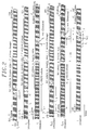
- the first and third lines in Figure 2 respectively show a downlink frame transmitted from line terminal 1 to digital terminations 2aisons to 2 I and a user sector S ' i consisting of a group of elementary data cells and transmitted from a digital termination 2 i to the line terminal 1.
- the downlink frames transmitted from the line terminal 1 to the digital terminations 21 to 2 I , and the uplink frames formed at the coupler 11 and resulting from multiple distribution access in the time of groups of user cells at different bit rates transmitted by I 'user terminals in communication among the I user terminals 31 to 3 I , the whole I' being less than I, have a period T 1 ms and each include 384 elementary data cells.
- Downlink and uplink frames are transmitted simultaneously by multiplexing of first and second different wavelengths.
- the downlink frames are transmitted at the first wavelength from line terminal 1 to the digital terminations 21 to 2 I , and the user sectors, such as the sector S ' i in the third line of FIG. 2, modulate the second wavelength in the digital terminations in communication for transmission to the terminal line 1.
- Each downlink frame successively comprises a management sector G with 8 data cells, a useful data field reserved for 352 cells distributed in at most I 'user sectors, called groups of cells, intended respectively for I' user terminals in communication among the I terminals 31 to 3 I , and an empty sector of SVD data having a length of 24 cells.
- Each uplink frame such as that shown in the sixth line in Figure 2, is delimited by a header alignment sector SAE and an end frame alignment sector SAF which surround a field of data useful for 352 cells including the user cell sectors transmitted to the line terminal 1 respectively from the respective user terminals in communication and a management sector G 'with 8 cells.
- the SAE and SAF header and end-of-frame alignment sectors comprise 10 and 14 elementary data cells respectively.
- asynchronous data at high ATM speed of 155.520 Mbit / s coexist in the uplink and downlink frames with synchronous service data whose rates are, for example, rates of the plesiochronous hierarchy N x 2048 kbit / s.
- the allocation of a bit rate to a user terminal 3 i results from the allocation of a given number of time cells in the uplink and downlink frames to data cells transmitted and received by this terminal.
- Each user terminal in communication is allocated one or more time cells in each frame according to the speed of the terminal.
- user sectors such as sectors S i and S i + 3 in the descending frame and sectors S ' i and S' i + 3 in the ascending frame, formed of consecutive elementary cells in the frame, user sectors can be formed by non-consecutive cells in the frame.
- the time window defining a time cell coincides with a integer number of bits and that a cell start instant coincides with a bit start phase, whatever the bit rate and this although the ATM bit rate at 155.520 Mbit / s is not multiple of the low bit rates of the plesiochronous hierarchy and basic access.
- each time cell since the asynchronous ATM temporal technique is characterized by an information transfer unit, called a packet, comprising (53 x 8) bits at 155.520 Mbit / s, i.e. 53 bytes at 19.440 Mbytes / s, each time cell must have a duration such that it comprises at least (53 x 8) bits at 155.520 Mbit / s.
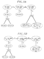
- the second approach shown diagrammatically in FIG. 3B, aims to satisfy the requirements (a) and (b) set out above and, moreover, to the following requirement: (c ')
- the broadband online associated with the ATM bandwidth is only a multiple of the number of bits per elementary data cell, which bits are at the online bandwidth associated with the ATM data bandwidth, and this broadband is not an integral multiple ATM speed.
- This second approach sacrificing the requirement for an online broadband which is a multiple of the ATM throughput, unlike the first approach, implies a higher cost of the clock components for sending and receiving ATM data online.
- each elementary data cell must contain a number of bits, at the line rate associated with the ATM rate, substantially greater than or equal to the number of bits in a standardized ATM packet, namely (8 x 53) bits, so that a cell contains an ATM packet.
- N3 is at least equal to 23.
- the latter high speed value is difficult to implement.
- this first approach can be adopted for asynchronous services at bit rates lower than the standardized ATM bit rate of 155,520 Mbit / s.
- FIG. 3B Only the second approach (FIG. 3B) provides more acceptable solutions for a number of bits per elementary cell at the line rate associated with the ATM rate equal to or substantially greater than (53 ⁇ 8) bits, by sacrificing the fact of having a high online speed associated with the ATM speed multiple of the ATM speed, and therefore to use clocks of transmission and reception of online data at a lower cost.
- terminations 21 to 2 I and the line terminal 1 There are two types of terminations: on the one hand, so-called high-speed terminations typically operating at ATM or at high rates of the plesiochronous hierarchy and using optical duplexers, and, on the other hand, so-called low-rate terminations operating for example at low rates of the plesiochronous hierarchy or at the basic ISDN access rate and using reversible optical components.
- the first and last lines of FIG. 2 respectively show a downlink frame transmitted from the line terminal 1 to each of the digital terminations 21 to 2 I and an uplink frame.
- the management sectors G ′ and G, with eight cells each, in the uplink and downlink frames are intended respectively for first management words to request the allocation of elementary cells of data by the digital terminations 21 and 2 I , and second management words for assigning elementary cells to these requesting terminations, these second words being transmitted by the line terminal 1.
- the first and second management words have respective online bit rates associated with the data rates of the user terminals 31 to 3 I so that they can be sent, received and interpreted directly by the 21 to 2 I terminations without requiring additional synchronization means.
- management sectors G and G ′ are thus defined three sub-sectors with online bit rates D1, D2 and D3 associated respectively with low speed, medium speed and high data speed of terminals 31 to 3 I. Each of these sub-sectors is intended, in turn, for each of the terminations in communication at the speed concerned.
- the management sectors G and G ′ further contain respective synchronization words at the different online bit rates intended to periodically synchronize the terminations and the line terminal.
- the downlink frame also contains 352 useful data cells forming the user sectors, such as the sectors S i and S i + 3 respectively intended for digital low-speed terminations 2 i and 2 i + 3 .
- the downlink frame shown in the first line is received with respective delays ⁇ i and ⁇ i + 3 by the two low bit rate terminations 2 i and 2 i + 3 to which are respectively for the S i and S i + 3 sectors.
- the delays ⁇ i and ⁇ i + 3 depend on the lengths L i and L i + 3 of the respective optical fibers separating the line terminal 1 and the low-speed digital terminations 2 i and 2 i + 3 .
- the digital terminations 21 to 2 I are synchronized periodically at the frame frequency with respective synchronization words at the various online rates provided in the management sector G. Thanks to the prior transmission of first and second management words in the sectors of management G and G ', respective sectors of elementary cells are assigned to the I' ends in communication among the I terminations 21 to 2 I. A user sector constituting a group of cells is assigned to a termination given by the line terminal 1 by introducing the ranks of these cells in the frame, in respective management words of management sectors G.
- the synchronization words at the different bit rates transmitted in the management sector G allow the different terminations to be synchronized with the frame and thus establish respective time windows coinciding with the time cells containing the data cells which are respectively intended for them.
- the third and fifth lines in Figure 2 show two user sectors S ' i and S' i + 3 transmitted respectively low-speed terminations 2 i and 2 i + 3 to line terminal 1 and intended to form part of 'a rising frame shown in the sixth line in this figure 2.
- the sectors S' i and S ' i + 3 are shown inserted in a frame only for the purpose of explanation; only the sectors S ' i and S' i + 3 are actually established and transmitted respectively by the low-speed terminations 2 i and 2 i + 3 .
- the first useful field cell in the down frame corresponds to the 177th useful field cell in the up frame and the 177th and 352nd cells in the down frame correspond to the first and 176th up frame cells.
- the full duplex transmission mode implementing this row shift between uplink frame cells and associated downlink frame cells for low bit rate terminations ensures that low bit rate terminations transmit and receive in alternating using reversible optical components since data cells are not simultaneously transmitted and received by the same digital termination 2 i , and, on the other hand, guarantees that high-speed terminations transmit and receive simultaneously data cells using optical duplexers.
- high-speed terminations are assigned up and down frame cells which are not occupied by data cells transmitted and received by the low-rate terminations.
- the rank of an uplink frame cell associated with a downlink frame cell does not systematically correspond to the rank of said downlink frame cell added to the rank of the middle cell of the useful data field, namely 352 / 2.
- the first cell, or the first sector, free of uplink frame is allocated to the digital termination at high data rate for which a cell, or sector, of downlink frame is intended.
- a time cell or a group of time cells not occupied by low bit rate data in the down frame corresponds to a cell or a group of cells not occupied by low bit rate data in the up frame and having a location necessarily offset by a half-period of useful data field with respect to that in the downlink frame.
- the line terminal 1 searches for a first cell or a first group of available cells in the uplink frame to allocate it to the high speed digital termination by transmitting the row or rows in binary code of these cells in the downlink frame.
- the prior art only provides, as described in FR-B-2 636 482 and EP-A-485 260, for guaranteeing a half-day transmission by proposing that a downlink frame including sectors d the user is transmitted from the line terminal 1 to the terminals 21 to 2 I and that, following the reception by all the terminals 21 to 2 I of the entire downlink frame, the respective user sectors are transmitted by the termination in communication 21 to 2 I to line terminal 1 to form a rising frame.
- the prior art is not optimal with respect to broadband transmissions since a termination cannot simultaneously transmit and receive.
- the number of cells allocated to a low-speed digital termination is at most equal to half the number of cells in the payload field . This limitation of the number of cells allocated to the same digital termination at low speed avoids any simultaneous transmission and reception of cells by this digital termination given the offset numeric of rows between uplink frame cells and associated down frame cells.
- the (64-53) x8 bit locations not used by an ATM packet in each downlink frame cell and therefore empty of useful data are filled by the line terminal 1 by a rank in binary code to be assigned to an uplink frame cell associated with said each cell.
- This solution avoids resorting to the management sector G systematically for each packet of an ATM burst and therefore aims to satisfy real-time operating constraints relating to ATM.
Abstract
Description
La présente invention concerne, de manière générale, l'accès multiple à répartition dans le temps et le multiplexage temporel dans des réseaux de télécommunications. Plus particulièrement, l'invention a trait à des structures de trame multidébit, également appelée trame multivitesse, pour réseaux de télécommunications étoilés arborescents notamment des réseaux à fibre optique.The present invention relates, in general, to time division multiple access and time division multiplexing in telecommunications networks. More particularly, the invention relates to multi-rate frame structures, also called multi-speed frame, for tree-shaped star telecommunications networks, in particular fiber optic networks.
Une trame multidébit, comme décrit dans la EP-A-0485260, est définie comme une trame obtenue par multiplexage à division du temps ou accès multiple à répartition dans le temps de données ayant des débits en ligne, c'est à dire des débits dans un support de transmission, qui sont différents ; ainsi un intervalle de temps, tel que cellule temporelle de trame, ayant une durée constante peut être alloué à un nombre de bits différent de celui alloué à un autre intervalle de temps en fonction des débits de sources dont sont issus les bits. Une trame multidébit de ce type diffère de la composition d'une trame classique qui résulte du multiplexage temporel de données à débits différents, en élevant ces débits différents à un unique débit résultant en ligne.A multi-bit frame, as described in EP-A-0485260, is defined as a frame obtained by time division multiplexing or time division multiple access of data having online rates, i.e. rates in a transmission medium, which are different; thus a time interval, such as frame time cell, having a constant duration can be allocated to a number of bits different from that allocated to another time interval as a function of the bit rates of sources from which the bits originate. A multi-rate frame of this type differs from the composition of a conventional frame which results from the time multiplexing of data at different rates, raising these different rates to a single resulting rate online.
Dans les réseaux partagés à fibre optique, la technique antérieure distingue principalement deux modes de transmission entre deux équipements qui sont le mode semi-duplex, dit également transmission à l'alternat, et le mode full-duplex, dit également transmission bidirectionnelle simultanée, qui résulte d'un multiplexage en longueur d'onde.In shared fiber-optic networks, the prior art mainly distinguishes two modes of transmission between two pieces of equipment which are the half-duplex mode, also called half-duplex transmission, and the full-duplex mode, also called two-way simultaneous transmission, which results from wavelength multiplexing.
Dans le mode semi-duplex, le sens de la transmission change alternativement. Pendant que l'un des équipements émet des données, l'autre équipement reçoit ces données, et inversement. Dans chaque équipement, il y a une phase d'émission et une phase de réception qui ne se recouvrent pas. Pour un débit de données prédéterminé D entre les deux équipements, le débit en ligne est au moins égal à 2D compte tenu du partage temporel alternatif du support de transmission entre les deux équipements. En fait, un temps de propagation et un temps de garde de suppression d'interférence augmente ce débit en ligne à une valeur sensiblement égale à 2,5 D.In the half-duplex mode, the direction of the transmission changes alternately. While one equipment transmits data, the other equipment receives this data, and vice versa. In each piece of equipment, there is a transmission phase and a reception phase which do not overlap. For a predetermined data rate D between the two devices, the online rate is at least equal to 2D taking into account the alternative time sharing of the transmission medium between the two devices. In fact, a propagation time and an interference suppression guard time increases this online throughput to a value substantially equal to 2.5 D.
Dans le mode de transmission full-duplex par multiplexage en longueur d'onde, chacun des deux équipements raccordés à des extrémités respectives d'une fibre optique émet avec une longueur d'onde respective dans cette fibre optique vers l'autre équipement.In the full-duplex transmission mode by wavelength multiplexing, each of the two pieces of equipment connected to respective ends of an optical fiber transmits with a respective wavelength in this optical fiber to the other piece of equipment.
Chacun de ces deux modes de transmission possède ses propres avantages et inconvénients.Each of these two modes of transmission has its own advantages and disadvantages.
Le mode semi-duplex est particulièrement bien adapté à la transmission de données à bas débit. Le doublement du débit en ligne n'est pas limitatif à ces débits pour les équipements et support de transmission, et il peut être mis en oeuvre par utilisation de composants réversibles d'émission/réception peu coûteux. Notamment, une seule diode peut être utilisée en émission et réception en inversant la polarisation de celle-ci. Une telle diode présente une plage de fréquences de fonctionnement autorisant son utilisation à des fréquences respectives différentes en émission et réception. Le mode de transmission par multiplexage en longueur d'onde est la seule technique efficace pour des données à haut débit ; il recourt à des duplexeurs optiques coûteux nécessaires pour la mise en oeuvre simultanément d'une réception à une première longueur d'onde et d'une transmission à une seconde longueur d'onde.The half-duplex mode is particularly well suited to low-speed data transmission. Doubling the online speed is not limiting to these speeds for equipment and transmission medium, and it can be implemented by using inexpensive reversible transmission / reception components. In particular, a single diode can be used in transmission and reception by reversing the polarization thereof. Such a diode has a range of operating frequencies authorizing its use at respective respective frequencies in transmission and reception. Wavelength division multiplex transmission mode is the only effective technique for high speed data; it uses expensive optical duplexers necessary for the simultaneous implementation of a reception at a first wavelength and of a transmission at a second wavelength.
Le principal objectif de cette invention est de fournir une structure de trame pour réseaux de télécommunications étoilés arborescents mettant en oeuvre le mode de transmission par multiplexage en longueur d'onde selon lequel une trame descendante périodique, produite par un équipement central et destinée à une pluralité d'équipements terminaux, et une trame montante constituée par des groupes de cellules d'usager respectivement produits par des équipements terminaux et destinés à l'équipement central, sont transmises à deux longueurs d'onde respectives différentes en mode bidirectionnel simultané, tout en garantissant un mode de transmission à l'alternat pour chaque équipement terminal à bas débit relativement à deux groupes de cellules de données d'usager des trames montante et descendante respectivement transmis par ledit chaque équipement terminal à bas débit et destiné à ledit chaque équipement terminal à bas débit. Le mode de transmission full-duplex est par contre effectif pour les équipements terminaux à haut débit lorsque cela est possible.The main objective of this invention is to provide a frame structure for tree-shaped star telecommunications networks implementing the transmission mode by wavelength multiplexing according to which a periodic downward frame, produced by central equipment and intended for a plurality of terminal equipment, and an uplink frame constituted by groups of user cells produced respectively by terminal equipment and intended for the central equipment, are transmitted at two respective respective wavelengths in simultaneous bidirectional mode, while ensuring a half-duplex transmission mode for each low-speed terminal equipment relative to two groups of user data cells of the uplink and downstream frames respectively transmitted by said each low-speed terminal equipment and intended for said each low-speed terminal equipment debit. On the other hand, the full-duplex transmission mode is effective for high-speed terminal equipment when possible.
Afin de garantir un mode de transmission à l'alternat pour chaque équipement terminal à bas débit transmettant et recevant des premières cellules de données, des trames descendante et montante périodiques multidébits transmises en mode full-duplex à travers une ligne bidirectionnelle arborescente respectivement à une première longueur d'onde depuis un équipement central vers une pluralité d'équipements terminaux et à une seconde longueur d'onde différente de la première longueur d'onde depuis la pluralité d'équipements terminaux vers l'équipement central, les équipements terminaux recevant et transmettant des cellules de données ayant une durée constante respectivement avec des débits en ligne respectifs différents,
dans lesdites trames descendante et montante, un champ de données utiles étant réservé à des cellules temporelles consécutives en un nombre prédéterminé qui sont destinées à être occupées par des cellules de données respectivement reçues et transmises par des équipements terminaux en communication avec l'équipement central , chaque cellule de données dans ledit champ de données utiles étant localisée par un rang,
sont caractérisées en ce que
à des premières cellules de données dans la trame descendante qui sont reçues par un équipement terminal en communication et qui ont des rangs donnés dans ledit champ de données utiles correspondent des premières cellules de données dans la trame montante transmises par ledit équipement terminal en communication qui ont des rangs dans ledit champ de données utiles respectivement égaux à des premières sommes d'un entier prédéterminé au moins égal à un et desdits rangs donnés modulo le nombre prédéterminé de cellules temporelles dans ledit champ de données utiles.In order to guarantee a half-duplex transmission mode for each low-speed terminal device transmitting and receiving first data cells, periodic multi-bit down and up frames transmitted in full-duplex mode through a bidirectional line tree respectively at a first wavelength from a central equipment to a plurality of terminal equipment and at a second wavelength different from the first wavelength from the plurality of terminal equipment to the central equipment, the terminal equipment receiving and transmitting data cells having a constant duration respectively with different respective online bit rates,
in said downlink and uplink frames, a useful data field being reserved for consecutive time cells in a predetermined number which are intended to be occupied by data cells respectively received and transmitted by terminal equipment in communication with the central equipment, each data cell in said useful data field being located by a row,
are characterized in that
first data cells in the down frame which are received by a terminal equipment in communication and which have given ranks in said useful data field correspond to first data cells in the up frame transmitted by said terminal equipment in communication which have rows in said useful data field respectively equal to first sums of a predetermined integer at least equal to one and said rows given modulo the predetermined number of time cells in said useful data field.
En pratique, des groupes respectifs de premières cellules de données sont attribués dans les trames à des équipements terminaux en communication et l'entier prédéterminé est sensiblement égal à la moitié du nombre prédéterminé de cellules temporelles dans ledit champ de données utiles.In practice, respective groups of first data cells are allocated in the frames to terminal equipment in communication and the predetermined integer is substantially equal to the half of the predetermined number of time cells in said payload field.
Par contre, pour les terminaisons à haut débit transmettant et recevant des secondes cellules de données, le mode full-duplex est garanti dans la mesure du possible. Pour cela, des secondes cellules de données dans ladite trame montante, qui sont associées à des secondes cellules de données dans ladite trame descendante reçues par un équipement terminal, sont transmises par ledit équipement terminal dans des premières cellules temporelles dudit champ de données utiles non occupées par des premières cellules de données.On the other hand, for high-speed terminations transmitting and receiving second data cells, full-duplex mode is guaranteed as far as possible. For this, second data cells in said uplink frame, which are associated with second data cells in said downlink frame received by a terminal equipment, are transmitted by said terminal equipment in first time cells of said unoccupied payload field by first data cells.
Compte tenu du caractère sporadique des communications ATM et afin d'éviter d'avoir recours systématiquement à un secteur de gestion prévu dans la trame descendante, une seconde cellule de données de trame descendante transmise à un équipement terminal contient le rang d'une première cellule temporelle non occupée dans la trame montante.Given the sporadic nature of ATM communications and in order to avoid systematically having to use a management sector provided for in the downlink frame, a second downlink frame data cell transmitted to a terminal equipment contains the rank of a first cell time not occupied in the rising frame.
Selon une réalisation préférée de l'invention, les débits de données des équipements terminaux sont 192 kbits/s, N x 2048 kbits avec N > 1, et 155,520 Mbit/s, et la durée de chaque cellule temporelle coïncide avec 64 octets au débit en ligne de 196,608 Mbit/s associé au débit de données d'équipement terminal de 155,520 Mbit/s. Ainsi une cellule temporelle contient un paquet ATM de 53 octets.According to a preferred embodiment of the invention, the data rates of the terminal equipment are 192 kbits / s, N x 2048 kbits with N> 1, and 155.520 Mbit / s, and the duration of each time cell coincides with 64 bytes at the rate line of 196.608 Mbit / s associated with the data rate of terminal equipment of 155.520 Mbit / s. Thus a time cell contains an ATM packet of 53 bytes.
D'autres caractéristiques et avantages de la présente invention apparaîtront plus clairement à la lecture de la description suivante de plusieurs réalisations préférées de l'invention en référence aux dessins annexés correspondants dans lesquels :
- la figure 1 est un bloc-diagramme schématique d'un réseau de distribution étoilé arborescent à fibre optique selon la technique antérieure ;
- la figure 2 montre des diagrammes temporels de trames montante et descendante transmises entre un terminal de ligne et des terminaisons de réseau dans le réseau de distribution de la figure 1 ; et
- les figures 3A et 3B sont des diagrammes respectifs de deux plans de fréquence de débits de données en ligne dans les trames de la figure 2.
- FIG. 1 is a schematic block diagram of an arborescent star distribution network with optical fiber according to the prior art;
- FIG. 2 shows time diagrams of up and down frames transmitted between a line terminal and network terminations in the distribution network of FIG. 1; and
- FIGS. 3A and 3B are respective diagrams of two frequency plans of online data rates in the frames of FIG. 2.
En référence à la figure 1, un équipement central et des équipements terminaux dans un réseau de distribution étoilé arborescent à fibre optique contribuant à l'établissement de trames selon l'invention consistent typiquement en un terminal de ligne optique (TLO) 1 et I terminaisons numériques de réseau optique (TNRO) 2₁ à 2I. Trois ports d'entrée/sortie du terminal 1 sont connectés respectivement à des liaisons de natures et débits différents, telles qu'une liaison asynchrone A.T.M. (Asynchronous Terminal Mode) à un débit de 155,520 Mbit/s, une liaison plésiochrone à un débit de N.2048 kbit/s, N étant un entier positif, une liaison conforme à la Recommandation V5 du C.C.I.T.T. pour l'accès de base au réseau numérique à intégration de services RNIS à 192 kbit/s ou encore une liaison analogique. Un coupleur optique passif 11, ou bien plusieurs coupleurs optiques (non représentés) répartis suivant une ligne de transmission bidirectionnelle arborescente, couple le terminal 1 aux I terminaisons numériques 2₁ à 2I qui sont respectivement connectées à I terminaux d'usager 3₁ à 3I.With reference to FIG. 1, central equipment and terminal equipment in a tree-starred optical fiber distribution network contributing to the establishment of frames according to the invention typically consist of an optical line terminal (TLO) 1 and I terminations digital optical network (TNRO) 2₁ to 2 I. Three input / output ports of
Trois entrées du terminal de ligne optique 1 reçoivent respectivement des données au haut débit ATM, au débit plésiochrone et au bas débit conforme à la recommandation V5. Le terminal 1 regroupe les données de chaque liaison en des cellules de données ayant une durée prédéterminée et multiplexe ces données par groupes de cellules. Les cellules ont différents débits en ligne qui coexistent dans des trames descendantes transmises vers les terminaisons numériques 2₁ à 2I. Le coupleur optique 11 possède un premier accès relié au terminal de ligne optique 1 par une fibre optique FO, et I seconds accès reliés respectivement aux I terminaisons numériques 2₁ à 2I par I fibres optiques FO₁ à FOI. Les trames produites par le terminal de ligne 1 sont acheminées vers chacune des terminaisons numériques 2₁ à 2I à travers le coupleur 11 et via les I fibres optiques respectives.Three inputs of the
Il est à noter, tout au long de la description qui suit, que les problèmes de synchronisation relatifs à la formation des trames montantes reçues par le terminal de ligne 1 à partir de groupes de cellules respectifs transmis par les terminaisons numériques (usagers) 2₁ à 2I ne sont pas considérés. Le procédé retenu pour cette synchronisation est par exemple celui décrit dans le brevet français FR-B-2 636 482. Ce procédé considère la disparité des temps de propagation de données entre les différentes terminaisons numériques 2₁ à 2I et le terminal de ligne 1, puisque les fibres optiques entre les terminaisons numériques 2₁ à 2I et le coupleur passif 11 ont des longueurs respectives L₁ à LI différentes. En fonction des longueurs de fibre optique respectives L₁ à LI, des retards correcteurs respectifs sont appliqués aux transmissions de données dans les terminaisons numériques 2₁ à 2I afin de former par accès multiple à répartition dans le temps, au niveau du coupleur 11, des trames montantes de groupes de cellules d'usager contigus, en excluant tout chevauchement entre cellules transmises par deux terminaisons numériques distinctes et tout espacement inutile vide de données entre deux cellules successives.It should be noted, throughout the following description, that the synchronization problems relating to the formation of uplink frames received by the
Les première et troisième lignes dans la figure 2 respectivement montrent une trame descendante transmise du terminal de ligne 1 vers les terminaisons numériques 2₁ à 2I et un secteur d'usager S'i constitué par un groupe de cellules de données élémentaires et transmis depuis une terminaison numérique 2i vers le terminal de ligne 1. Les trames descendantes, transmises du terminal de ligne 1 vers les terminaisons numériques 2₁ à 2I, et les trames montantes formées au niveau du coupleur 11 et résultant d'un accès multiple à répartition dans le temps de groupes de cellules d'usager à différents débits transmis par I' terminaux d'usager en communication parmi les I terminaux d'usager 3₁ à 3I, l'entier I' étant inférieur à I, ont une période T = 1 ms et comprennent chacune 384 cellules de données élémentaires. Des trames descendantes et montantes sont transmises simultanément par multiplexage de première et seconde longueurs d'onde différentes. Les trames descendantes sont transmises à la première longueur d'onde du terminal de ligne 1 vers les terminaisons numériques 2₁ à 2I, et les secteurs d'usager, tels que le secteur S'i à la troisième ligne de la figure 2, modulent la seconde longueur d'onde dans I' terminaisons numériques en communication pour une transmission vers le terminal de ligne 1.The first and third lines in Figure 2 respectively show a downlink frame transmitted from
Chaque trame descendante comprend successivement un secteur de gestion G à 8 cellules de données, un champ de données utiles réservé à 352 cellules réparties dans au plus I' secteurs d'usagers, dits groupes de cellules, destinés respectivement à I' terminaux d'usager en communication parmi les I terminaux 3₁ à 3I, et un secteur vide de données SVD ayant une longueur de 24 cellules. Chaque trame montante, telle que celle montrée à la sixième ligne dans la figure 2, est délimitée par un secteur d'alignement d'en-tête SAE et un secteur d'alignement de fin de trame SAF qui encadrent un champ de données utiles à 352 cellules incluant I' secteurs de cellules d'usager transmis vers le terminal de ligne 1 respectivement depuis les terminaux d'usager en communication respectifs et un secteur de gestion G' à 8 cellules. Les secteurs d'alignement d'en-tête et de fin de trame SAE et SAF comprennent respectivement 10 et 14 cellules élémentaires de données.Each downlink frame successively comprises a management sector G with 8 data cells, a useful data field reserved for 352 cells distributed in at most I 'user sectors, called groups of cells, intended respectively for I' user terminals in communication among the
Selon l'invention, des données à caractère asynchrone au haut débit ATM de 155,520 Mbit/s coexistent dans les trames montantes et descendantes avec des données de service synchrone dont les débits sont, par exemple, des débits de la hiérarchie plésiochrone N x 2048 kbit/s. L'attribution d'un débit à un terminal d'usager 3i résulte de l'allocation d'un nombre donné de cellules temporelles des trames montante et descendante à des cellules de données transmises et reçues par ce terminal. A chaque terminal d'usager en communication est attribuée une ou plusieurs cellules temporelles dans chaque trame en fonction du débit du terminal. Bien que la figure 2 montre des secteurs d'usager, tels que les secteurs Si et Si+3 dans la trame descendante et les secteurs S'i et S'i+3 dans la trame montante, formés de cellules élémentaires consécutives dans la trame, des secteurs d'usager peuvent être formés par des cellules non consécutives dans la trame.According to the invention, asynchronous data at high ATM speed of 155.520 Mbit / s coexist in the uplink and downlink frames with synchronous service data whose rates are, for example, rates of the plesiochronous hierarchy N x 2048 kbit / s. The allocation of a bit rate to a
Pour la définition de la taille des cellules temporelles, deux contraintes doivent être satisfaites. D'une part, afin de faciliter la synchronisation, tant en émission qu'en réception, des terminaisons numériques avec les cellules de données dans les cellules temporelles qui leur sont allouées, il est nécessaire que la fenêtre temporelle définissant une cellule temporelle coïncide avec un nombre entier de bits et qu'un instant de début de cellule coïncide avec une phase de début de bit, quel que soit le débit et cela bien que le débit ATM à 155,520 Mbit/s ne soit pas multiple des bas débits de la hiérarchie plésiochrone et d'accès de base. D'autre part, puisque la technique temporelle asynchrone ATM est caractérisée par une unité de transfert d'informations, appelé paquet, comprenant (53 x 8) bits à 155,520 Mbit/s, c'est-à-dire 53 octets à 19,440 Moctets/s, chaque cellule temporelle doit avoir une durée telle qu'elle comprend au moins (53 x 8) bits à 155,520 Mbit/s.For the definition of the size of the time cells, two constraints must be satisfied. On the one hand, in order to facilitate the synchronization, both in transmission and in reception, of the digital terminations with the data cells in the time cells which are allocated to them, it is necessary that the time window defining a time cell coincides with a integer number of bits and that a cell start instant coincides with a bit start phase, whatever the bit rate and this although the ATM bit rate at 155.520 Mbit / s is not multiple of the low bit rates of the plesiochronous hierarchy and basic access. On the other hand, since the asynchronous ATM temporal technique is characterized by an information transfer unit, called a packet, comprising (53 x 8) bits at 155.520 Mbit / s, i.e. 53 bytes at 19.440 Mbytes / s, each time cell must have a duration such that it comprises at least (53 x 8) bits at 155.520 Mbit / s.
Pour satisfaire ces deux contraintes, deux approches sont offertes en posant comme condition que les débits en ligne dans des trames montantes et descendantes respectivement associés aux débits ATM, plésiochrone et d'accès de base sont multiples entre eux afin que chaque cellule temporelle de trame soit limitée à un intervalle temporel coïncidant avec un nombre entier de bits, quel que soit le débit en ligne. Cette condition conduit à choisir des horloges d'émission et de réception de données en ligne dans les terminaisons numériques 2₁ à 2I et le terminal de ligne 1 avec des fréquences respectives supérieures, ou le cas échéant égales, aux fréquences des données produites par les terminaux d'usager 3₁ à 3I, afin de ne pas installer des mémoires tampons de tailles prohibitives dans les terminaisons 2₁ à 2I et le terminal de ligne 1 pour compenser des écarts entre débits en ligne et débits de données associés.To satisfy these two constraints, two approaches are offered with the condition that the online bit rates in uplink frames and downstream respectively associated with ATM, plesiochronous and basic access rates are multiple between them so that each frame time cell is limited to a time interval coinciding with an integer number of bits, whatever the online rate. This condition leads to choosing clocks for sending and receiving data online in the digital terminals 2₁ to 2 I and the
La première approche, représentée sous forme schématique à la figure 3A, vise à satisfaire aux exigences suivantes :
- (a) Les débits en ligne sont multiples de l'un d'eux, comme signalé par les coefficients entiers k₁ et k₂.
- (b) Les débits en ligne sont multiples des débits de données associés, ou multiples d'un plus petit commun multiple PPCM d'un ensemble de débits de données, tel que le débit en ligne de 768 Mbit/s pour les débits de
données 192 Mbit/s et 256 Mbit/s, comme signalé par les coefficients entiers N1, N2 et N3. Cette exigence facilite la réalisation de chacune des horloges de réception et d'émission de données en ligne dans les terminaisons numériques et le terminal de ligne en combinant un multiplieur de fréquence avec une horloge couramment employée à une fréquence correspondante à un débit de données, ce qui évite ainsi de faire appel à des composants peu répandus ou spécifiques qui sont donc de coût plus élevé. - (c) Le haut débit en ligne associé au débit de données ATM est d'une part, comme mentionné en (b), multiple du débit ATM et, d'autre part, multiple entier du nombre de bits par cellule élémentaire de données, lesquels bits sont au débit en ligne associé au débit de données ATM. Le premier point précité résulte de la considération énoncée dans le paragraphe (b) ci-dessus concernant le coût des horloges aux fréquences des débits en ligne, et le second point garantit un nombre entier de cellules élémentaires par trame. Les trames montantes et descendantes ont une période égale à 1 ms et le débit en ligne associé au débit de données ATM s'écrit sous la forme datm kbit/s, soit datm bit/ms, et donc le nombre de bits par trame au débit en ligne associé au débit ATM est égal à datm. Si ce nombre datm est multiple du nombre de bits par cellule élémentaire au débit en ligne associé au débit ATM, il y a donc un nombre entier de cellules dans la trame. Ce second point assure une continuité de synchronisation d'une trame à la trame suivante.
- (a) Online debits are multiple of one of them, as indicated by the integer coefficients k₁ and k₂.
- (b) Online rates are multiple of the associated data rates, or multiples of a smaller common multiple PPCM of a set of data rates, such as the online rate of 768 Mbit / s for
data rates 192 Mbit / s and 256 Mbit / s, as indicated by the integer coefficients N1, N2 and N3. This requirement facilitates the production of each of the clocks for receiving and transmitting data online in the digital terminations and the line terminal by combining a frequency multiplier with a clock commonly used at a frequency corresponding to a data rate, this who avoids thus to use uncommon or specific components which are therefore of higher cost. - (c) The online broadband associated with the ATM data rate is on the one hand, as mentioned in (b), a multiple of the ATM rate and, on the other hand, an integer multiple of the number of bits per elementary data cell, which bits are at the online rate associated with the ATM data rate. The first point mentioned above results from the consideration stated in paragraph (b) above concerning the cost of clocks at the frequencies of the line speeds, and the second point guarantees an integer number of elementary cells per frame. The uplink and downlink frames have a period equal to 1 ms and the online bit rate associated with the ATM data rate is written in the form of atm kbit / s, i.e. atm bit / ms, and therefore the number of bits per frame the online speed associated with the ATM speed is equal to d atm . If this number of atm is multiple of the number of bits per elementary cell at the line rate associated with the ATM rate, there is therefore an integer number of cells in the frame. This second point ensures continuity of synchronization from one frame to the next frame.
La seconde approche, schématisée dans la figure 3B, vise à satisfaire aux exigences (a) et (b) énoncées ci-dessus et, en outre , à l'exigence suivante :
(c') Le haut débit en ligne associé au débit ATM est uniquement multiple du nombre de bits par cellule élémentaire de données, lesquels bits sont au débit en ligne associé au débit des données ATM, et ce haut débit n'est pas multiple entier du débit ATM.The second approach, shown diagrammatically in FIG. 3B, aims to satisfy the requirements (a) and (b) set out above and, moreover, to the following requirement:
(c ') The broadband online associated with the ATM bandwidth is only a multiple of the number of bits per elementary data cell, which bits are at the online bandwidth associated with the ATM data bandwidth, and this broadband is not an integral multiple ATM speed.
Cette seconde approche, sacrifiant l'exigence d'un haut débit en ligne qui est multiple du débit ATM, contrairement à la première approche, implique un coût plus élevé des composants d'horloge d'émission et de réception des données ATM en ligne.This second approach, sacrificing the requirement for an online broadband which is a multiple of the ATM throughput, unlike the first approach, implies a higher cost of the clock components for sending and receiving ATM data online.
En pratique, la première approche pose aujourd'hui des problèmes de faisabilité, les fréquences d'horloge d'émission et de réception des données ATM en ligne pouvant devenir trop élevées. Chacune de ces approches est basée en outre sur le fait que chaque cellule élémentaire de données doit contenir un nombre de bits, au débit en ligne associé au débit ATM, sensiblement supérieur ou égal au nombre de bits dans un paquet ATM normalisé, soit (8 x 53) bits, afin qu'une cellule contienne un paquet ATM.In practice, the first approach today poses feasibility problems, since the clock frequencies for transmitting and receiving ATM data online may become too high. Each of these approaches is further based on the fact that each elementary data cell must contain a number of bits, at the line rate associated with the ATM rate, substantially greater than or equal to the number of bits in a standardized ATM packet, namely (8 x 53) bits, so that a cell contains an ATM packet.
A titre d'exemple, pour la première approche (figure 3A), il est proposé une cellule élémentaire à (60 x 8) bits au haut débit en ligne associé au débit ATM. Le plus petit commun multiple PPCM de (60x8) et 155520 est égal à 311040. Le débit en ligne minimal associé au débit ATM doit donc être choisi égal à 311040 kbit/s. Par ailleurs, et comme représenté par les coefficients entiers N2, N3 et k2, dans la figure 3A, cette première approche doit satisfaire la condition :![]()
soit:![]()
soit:![]()
![]()
is: ![]()
is: ![]()
Par comparaison entre les différents nombres et coefficients de part et d'autre de l'égalité de la dernière équation ci-dessus, N3 est au moins égal à 2³. Ainsi, le haut débit en ligne associé au débit ATM doit être choisi au minimum égal à 2³ x 311040 kbit/s = 2488320 kbit/s. Cette dernière valeur de haut débit est difficilement mise en oeuvre. Toutefois, cette première approche peut être retenue pour des services asynchrones à des débits inférieurs au débit ATM normalisé de 155,520 Mbit/s.By comparison between the different numbers and coefficients on either side of the equality of the last equation above, N3 is at least equal to 2³. Thus, the online broadband associated with the ATM speed must be chosen at least equal to 2³ x 311040 kbit / s = 2488320 kbit / s. The latter high speed value is difficult to implement. However, this first approach can be adopted for asynchronous services at bit rates lower than the standardized ATM bit rate of 155,520 Mbit / s.
Seule la seconde approche (figure 3B) fournit des solutions plus acceptables pour un nombre de bits par cellule élémentaire au débit en ligne associé au débit ATM égal ou sensiblement supérieur à (53 x 8) bits, en sacrifiant le fait d'avoir un haut débit en ligne associé au débit ATM multiple du débit ATM, et donc d'utiliser des horloges d'émission et de réception de données en ligne de moindre coût.Only the second approach (FIG. 3B) provides more acceptable solutions for a number of bits per elementary cell at the line rate associated with the ATM rate equal to or substantially greater than (53 × 8) bits, by sacrificing the fact of having a high online speed associated with the ATM speed multiple of the ATM speed, and therefore to use clocks of transmission and reception of online data at a lower cost.
La solution optimale est trouvée pour (64 x 8) bits par cellule élémentaire au haut débit en ligne associé au débit ATM. Cette solution, en se référant à la figure 3B, conduit aux deux équations eql et eq2 suivantes :![]()
![]()
soit :![]()
![]()
soit :![]()
![]()
![]()
![]()
is : ![]()
![]()
is : ![]()
![]()
De ces deux équations ainsi réduites sont déduits les résultats fréquentiels suivants, sachant que le haut débit en ligne associé au débit ATM doit être supérieur ou égal au débit ATM :
N3' = 384
k2' = 8
k1 = 8
N2 = 12
N1 = 4From these two equations thus reduced are deduced the following frequency results, knowing that the online broadband associated with the ATM speed must be greater than or equal to the ATM speed:
N3 '= 384
k2 '= 8
k1 = 8
N2 = 12
N1 = 4
Ainsi des débits en ligne D1, D2 et D3, respectivement associés aux débits de données 768 kbit/s, 2,048 Mbit/s et 155,520 Mbit/s, prennent les valeurs :
D1 = 3,072 Mbit/s
D2 = 24,576 Mbit/s
D3 = 196,608 Mbit/sThus, online rates D1, D2 and D3, respectively associated with
D1 = 3.072 Mbit / s
D2 = 24.576 Mbit / s
D3 = 196.608 Mbit / s
Chaque cellule élémentaire de données d'une trame montante ou descendante peut contenir 64 x 8 bits au débit en ligne D3 = 196,608 Mbit/s, ou 64 bits au débit en ligne D2 = 24,576 Mbit/s, ou bien 8 bits au débit en ligne D1 = 3,072 Mbit/s.Each elementary data cell of an uplink or downlink frame can contain 64 x 8 bits at the line speed D3 = 196.608 Mbit / s, or 64 bits at the line speed D2 = 24.576 Mbit / s, or else 8 bits at the line speed line D1 = 3.072 Mbit / s.
En référence de nouveau à la figure 2, les structures des trames montantes et descendantes transmises entre les terminaisons numériques 2₁ à 2I et le terminal de ligne 1 sont maintenant décrites en détail. On distingue deux types de terminaisons: d'une part les terminaisons dites à haut débit opérant typiquement au débit ATM ou à des débits élevés de la hiérarchie plésiochrone et utilisant des duplexeurs optiques, et, d'autre part, les terminaisons dites à bas débit fonctionnant par exemple aux bas débits de la hiérarchie plésiochrone ou au débit d'accès de base RNIS et utilisant des composants optiques réversibles.Referring again to FIG. 2, the structures of the up and down frames transmitted between the digital terminations 2₁ to 2 I and the
Les première et dernière lignes de la figure 2 montrent respectivement une trame descendante transmise du terminal de ligne 1 vers chacune des terminaisons numériques 2₁ à 2I et une trame montante. Les secteurs de gestion G' et G, à huit cellules chacun, dans les trames montante et descendante sont destinés respectivement à des premiers mots de gestion pour demander l'attribution de cellules élémentaires de données par les terminaisons numériques 2₁ et 2I, et des seconds mots de gestion pour attribuer des cellules élémentaires à ces terminaisons demanderesses, ces seconds mots étant transmis par le terminal de ligne 1. Les premiers et seconds mots de gestion ont des débits en ligne respectifs associés aux débits de données des terminaux d'usager 3₁ à 3I afin qu'ils puissent être émis, reçus et interprétés directement par les terminaisons 2₁ à 2I sans nécessiter des moyens de synchronisation supplémentaires. Dans les secteurs de gestion G et G' sont ainsi définis trois sous-secteurs aux débits en ligne D1, D2 et D3 associés respectivement aux bas débit, moyen débit et haut débit de données des terminaux 3₁ à 3I. Chacun de ces sous-secteurs est destiné, tour à tour, à chacune des terminaisons en communication au débit concerné. Les secteurs de gestion G et G' contiennent, en outre, des mots de synchronisation respectifs aux différents débits en ligne destinés à synchroniser périodiquement les terminaisons et le terminal de ligne.The first and last lines of FIG. 2 respectively show a downlink frame transmitted from the
La trame descendante contient également 352 cellules de données utiles formant I' secteurs d'usager, tels que les secteurs Si et Si+3 respectivement destinés aux terminaisons numériques à bas débit 2i et 2i+3.The downlink frame also contains 352 useful data cells forming the user sectors, such as the sectors S i and S i + 3 respectively intended for digital low-speed terminations 2 i and 2 i + 3 .
Comme montré aux deuxième et quatrième lignes de la figure 2, la trame descendante montrée à la première ligne est reçue avec des retards respectifs τi et τi+3 par les deux terminaisons à bas debit 2i et 2i+3 auxquelles sont respectivement destinés les secteurs Si et Si+3. Les retards τi et τi+3 dépendent des longueurs Li et Li+3 des fibres optiques respectives séparant le terminal de ligne 1 et les terminaisons numériques à bas débit 2i et 2i+3.As shown in the second and fourth lines of Figure 2, the downlink frame shown in the first line is received with respective delays τ i and τ i + 3 by the two low bit rate terminations 2 i and 2 i + 3 to which are respectively for the S i and S i + 3 sectors. The delays τ i and τ i + 3 depend on the lengths L i and L i + 3 of the respective optical fibers separating the
Les terminaisons numériques 2₁ à 2I sont synchronisées périodiquement à la fréquence de trame avec des mots de synchronisation respectifs aux différents débits en ligne prévus dans le secteur de gestion G. Grâce à la transmission préalable de premiers et seconds mots de gestion dans les secteurs de gestion G et G', des secteurs respectifs de cellules élémentaires sont attribués aux I' terminaisons en communication parmi les I terminaisons 2₁ à 2I. Un secteur d'usager constituant un groupe de cellules est attribué à une terminaison donnée par le terminal de ligne 1 en introduisant les rangs de ces cellules dans la trame, dans des mots de gestion respectifs de secteurs de gestion G. Les mots de synchronisation aux différents débits transmis dans le secteur de gestion G permettent aux différentes terminaisons d'être synchronisées avec la trame et ainsi établir des fenêtres temporelles respectives coïncidant avec les cellules temporelles contenant les cellules de données qui leur sont respectivement destinées.The digital terminations 2₁ to 2 I are synchronized periodically at the frame frequency with respective synchronization words at the various online rates provided in the management sector G. Thanks to the prior transmission of first and second management words in the sectors of management G and G ', respective sectors of elementary cells are assigned to the I' ends in communication among the I terminations 2₁ to 2 I. A user sector constituting a group of cells is assigned to a termination given by the
Les troisième et cinquième lignes de la figure 2 montrent deux secteurs d'usager S'i et S'i+3 transmis respectivement des terminaisons à bas débit 2i et 2i+3 vers le terminal de ligne 1 et destinés à former partie d'une trame montante montrée à la sixième ligne dans cette figure 2. Les secteurs S'i et S'i+3 sont représentés insérés dans une trame seulement à des fins d'explication ; seuls les secteurs S'i et S'i+3 sont effectivement établis et transmis respectivement par les terminaisons à bas débit 2i et 2i+3. Les parties hachurées en traits obliques dans les trames montrées aux troisième et cinquième lignes dans la figure 2, correspondent en fait à des temps morts de transmission respectivement dans les terminaisons à bas débit 2i et 2i+3.The third and fifth lines in Figure 2 show two user sectors S ' i and S' i + 3 transmitted respectively low-speed terminations 2 i and 2 i + 3 to
Chaque terminaison 2₁ à 2I est resynchronisée à chaque période de trame. Dans l'exemple montré à la troisième ligne, respectivement cinquième ligne, dans la figure 2, la terminaison à bas debit 2i, respectivement 2i+3, produit, en réponse à l'instant de début de réception de la trame descendante, chaque cellule d'un secteur S'i, respectivement S'i+3, de trame montante après une somme de premier et second retard suivants:
- (1)- Le premier retard est égal au produit de la durée d'une cellule par une somme d'un premier rang Ci, respectivement Ci+3, d'une cellule qui est associée à ladite chaque cellule d'un secteur de trame montante et qui est reçue dans le champ de données utiles de la trame descendante dans le secteur Si, respectivement Si+3, et d'un second rang, ici 352/2, d'une cellule médiane dans le champ de données utiles. Chaque cellule de trame montante possède une cellule associée dans une trame descendante puisque l'attribution d'un débit à une terminaison se caractérise par l'affectation de cellules en nombre égal dans les trames montantes et trames descendantes successives.
- (2)- Le second retard est la somme d'un temps de garde et d'un retard correcteur. Le retard correcteur est calculé selon le procédé défini dans la FR-A-2 636 482 et dépend de la longueur Li, respectivement Li+3, de la fibre optique FOi, respectivement FOi+3, séparant le terminal de ligne 1 de la terminaison à bas débit 2i, respectivement 2i+3. Le temps de garde est constant dans toutes les terminaisons 2i à 2I et égal à la durée d'au moins huit cellules consécutives incluses dans le secteur de gestion G ou G' afin que les terminaisons et le terminal 1 ne transmettent pas pendant la réception d'un secteur de gestion. Ce temps de garde serait en outre nécessaire au basculement de l'état de réception à l'état d'émission relativement à un secteur dans une terminaison à bas débit fonctionnant à l'alternat si l'émission d'un secteur, dans une trame montante, n'était pas différé de 352/2 cellules par rapport à la réception du secteur de même rang dans la trame descendante. Les retards correcteurs compensent les différences de temps de propagation proportionnels aux longueurs des fibres optiques FO₁ à FOI afin que les secteurs émis par les terminaisons en communication constituent sans chevauchement temporel la trame montante au niveau du coupleur 11 . Plus la terminaison est éloignée du coupleur 11, plus le retard correcteur est faible. Puisque la trame montante et la trame descendante contiennent 24 cellules vides dans les secteurs SVD et SAE et SAF, le retard correcteur peut être au plus égal à 24 - 8 = 16 cellules pour la terminaison la plus proche du coupleur 11. Ainsi, par exemple, selon la troisième ligne dans la figure 2, un retard correcteur 14 - 8 = 6 cellules est imposé dans la terminaison à bas débit 2i. Selon la cinquième ligne dans la figure 2, un retard correcteur de 10 - 8 = 2 cellules est imposé dans la terminaison 2i+3 qui est plus éloignée du coupleur 11 que la terminaison 2i.
- (1) - The first delay is equal to the product of the duration of a cell by a sum of a first rank C i , respectively C i + 3 , of a cell which is associated with said each cell of a sector of uplink frame and which is received in the payload field of the downlink in the sector S i , respectively S i + 3 , and of a second rank, here 352/2, of a median cell in the field of useful data. Each uplink frame cell has an associated cell in a frame downlink since the allocation of a throughput to a termination is characterized by the allocation of cells in equal number in the successive uplink and downlink frames.
- (2) - The second delay is the sum of a guard time and a corrective delay. The corrective delay is calculated according to the method defined in FR-A-2 636 482 and depends on the length L i , respectively L i + 3 , of the optical fiber FO i , respectively FO i + 3 , separating the
line terminal 1 of the low-speed termination 2 i , respectively 2 i + 3 . The guard time is constant in all the terminations 2 i to 2 I and equal to the duration of at least eight consecutive cells included in the management sector G or G 'so that the terminations and theterminal 1 do not transmit during the reception of a management area. This guard time would also be necessary for switching from the reception state to the transmission state relative to a sector in a low-speed termination operating in the half-cycle if the transmission of a sector, in a frame up, was not delayed by 352/2 cells compared to the reception of the sector of the same rank in the down frame. The corrective delays compensate for the differences in propagation time proportional to the lengths of the optical fibers FO₁ to FO I so that the sectors emitted by the terminations in communication constitute the uplink frame at thecoupler 11 without temporal overlap. The further the termination is from thecoupler 11, the smaller the correction delay. Since the rising frame and the falling frame contain 24 empty cells in the sectors SVD and SAE and SAF, the corrective delay can be at most equal to 24 - 8 = 16 cells for the termination closest to thecoupler 11. Thus, for example, according to the third line in FIG. 2, a corrector delay 14 - 8 = 6 cells is imposed in the low-rate termination 2 i . According to the fifth line in FIG. 2, a correction delay of 10 - 8 = 2 cells is imposed in the termination 2 i + 3 which is further from thecoupler 11 than the termination 2 i .
Selon la définition du premier retard et en référence à la trame montante montrée à la sixième ligne dans la figure 2 , chaque cellule d'un secteur S'i transmis de la terminaison à bas débit 2i vers le terminal de ligne 1 a un rang dans le champ de données utiles de la trame montante égal à la somme modulo 352 du rang Ci d'une cellule associée à ladite chaque cellule et transmise par le terminal de ligne 1 dans le secteur Si vers la terminaison 2i, et du rang 352/2 = 176 de la cellule médiane dans le champ de données utiles. Ainsi, la première cellule de champ utile dans la trame descendante correspond à la 177ième cellule de champ utile dans la trame montante et les 177ième et 352ième cellules dans la trame descendante correspondent aux première et 176ième cellules de trame montante.According to the definition of the first delay and with reference to the uplink frame shown in the sixth line in FIG. 2, each cell of a sector S ' i transmitted from the low-speed termination 2 i to the
Le mode de transmission full duplex mettant en oeuvre ce décalage de rang entre cellules de trame montante et cellules associées de trame descendante pour les terminaisons à bas débit, d'une part garantit que les terminaisons à bas débit transmettent et reçoivent en mode à l'alternat en utilisant des composants optiques réversibles puisque des cellules de données ne sont pas simultanément émises et reçues par une même terminaison numérique 2i, et, d'autre part garantit que les terminaisons à haut débit transmettent et reçoivent simultanément des cellules de données au moyen de duplexeurs optiques. En effet, selon l'invention, aux terminaisons à haut débit sont attribuées des cellules de trame montante et descendante qui ne sont pas occupées par des cellules de données émises et reçues par les terminaisons à bas débit. Pour ces terminaisons à haut débit, le rang d'une cellule de trame montante associée à une cellule de trame descendante ne correspond pas systématiquement au rang de ladite cellule de trame descendante additionné au rang de la cellule médiane du champ de données utiles, soit 352/2. La première cellule, ou le premier secteur, libre de trame montante est allouée à la terminaison numérique au haut débit de données à laquelle est destinée une cellule, ou un secteur, de trame descendante. En fonction de l'occupation des cellules temporelles de trame montante et des cellules temporelles de trame descendante ayant des rangs respectifs égaux aux sommes des rangs desdites cellules de trame montante et du rang d'une cellule médiane de champ de données utiles par des cellules de données émises et reçues par les terminaisons à bas débit, des émission et réception simultanées sont possibles dans une terminaison à haut débit notamment lorsque les trames montantes et descendantes sont peu remplies par des données émises et reçues par des terminaisons à bas débit. Il est à noter qu'à une cellule temporelle ou un groupe de cellules temporelles non occupée par des données à bas débit dans la trame descendante correspond une cellule ou un groupe de cellules non occupée par des données à bas débit dans la trame montante et ayant un emplacement nécessairement décalé d'une demi-période de champ de données utiles par rapport à celui dans la trame descendante. Dès qu'une cellule ou un groupe de cellules de données à haut débit est à transmettre par une terminaison à haut débit, le terminal de ligne 1 recherche une première cellule ou un premier groupe de cellules disponible dans la trame montante pour l'allouer à la terminaison numérique à haut débit en transmettant le ou les rangs en code binaire de ces cellules dans la trame descendante.The full duplex transmission mode implementing this row shift between uplink frame cells and associated downlink frame cells for low bit rate terminations, on the one hand ensures that low bit rate terminations transmit and receive in alternating using reversible optical components since data cells are not simultaneously transmitted and received by the same digital termination 2 i , and, on the other hand, guarantees that high-speed terminations transmit and receive simultaneously data cells using optical duplexers. In fact, according to the invention, high-speed terminations are assigned up and down frame cells which are not occupied by data cells transmitted and received by the low-rate terminations. For these broadband terminations, the rank of an uplink frame cell associated with a downlink frame cell does not systematically correspond to the rank of said downlink frame cell added to the rank of the middle cell of the useful data field, namely 352 / 2. The first cell, or the first sector, free of uplink frame is allocated to the digital termination at high data rate for which a cell, or sector, of downlink frame is intended. As a function of the occupancy of the uplink time cells and of the downlink time cells having respective ranks equal to the sums of the ranks of said uplink cells and the rank of a median field of useful data field by cells of data transmitted and received by low speed terminations, simultaneous transmission and reception are possible in a high speed termination in particular when the uplink and downlink frames are little filled with data transmitted and received by low speed terminations. It should be noted that a time cell or a group of time cells not occupied by low bit rate data in the down frame corresponds to a cell or a group of cells not occupied by low bit rate data in the up frame and having a location necessarily offset by a half-period of useful data field with respect to that in the downlink frame. From that a cell or a group of high speed data cells is to be transmitted by a high speed termination, the
Concernant la caractéristique précitée, la technique antérieure prévoit uniquement, comme décrit dans le FR-B-2 636 482 et la EP-A-485 260, de garantir une transmission à l'alternat en proposant qu'une trame descendante incluant des secteurs d'usager soit transmise du terminal de ligne 1 vers les terminaisons 2₁ à 2I et que, suite à la réception par toutes les terminaisons 2₁ à 2I de l'intégralité de la trame descendante, des secteurs d'usager respectifs soient transmis par les terminaisons en communication 2₁ à 2I vers le terminal de ligne 1 pour former une trame montante. Ainsi, la technique antérieure n'est pas optimale relativement aux transmissions à haut débit puisque une terminaison ne peut simultanément émettre et recevoir.With regard to the aforementioned characteristic, the prior art only provides, as described in FR-B-2 636 482 and EP-A-485 260, for guaranteeing a half-day transmission by proposing that a downlink frame including sectors d the user is transmitted from the
Afin d'éviter toute superposition de cellules transmises par et destinées à une même terminaison numérique à bas débit, le nombre de cellules attribuées à une terminaison numérique à bas débit est au plus égal à la moitié du nombre de cellules dans le champ de données utiles. Cette limitation du nombre de cellules attribuées à une même terminaison numérique à bas débit évite toute simultanéité d'émission et de réception de cellules par cette terminaison numérique compte tenu du décalage numérique de rangs entre cellules de trame montante et cellules de trame descendante associées.In order to avoid any overlapping of cells transmitted by and intended for the same low-speed digital termination, the number of cells allocated to a low-speed digital termination is at most equal to half the number of cells in the payload field . This limitation of the number of cells allocated to the same digital termination at low speed avoids any simultaneous transmission and reception of cells by this digital termination given the offset numeric of rows between uplink frame cells and associated down frame cells.
Selon une variante de l'invention, notamment destinée à s'adapter au caractère sporadique des transmissions asynchrones au débit ATM, les (64-53)x8 emplacements de bit non utilisés par un paquet ATM dans chaque cellule de trame descendante et donc vides de données utiles, selon l'exemple d'une cellule à (64x8) bits au haut débit en ligne préconisé ci-dessus, sont remplis par le terminal de ligne 1 par un rang en code binaire à attribuer à une cellule de trame montante associée à ladite chaque cellule. Cette solution évite de recourir au secteur de gestion G systématiquement pour chaque paquet d'une rafale ATM et vise ainsi à satisfaire à des contraintes de fonctionnement en temps réel relatives à l'ATM.According to a variant of the invention, in particular intended to adapt to the sporadic nature of asynchronous transmissions at ATM speed, the (64-53) x8 bit locations not used by an ATM packet in each downlink frame cell and therefore empty of useful data, according to the example of a cell with (64 × 8) bits at high speed online recommended above, are filled by the
Claims (9)
dans lesdites trames descendante et montante, un champ de données utiles étant réservé à des cellules temporelles consécutives en un nombre prédéterminé qui sont destinées à être occupées par des cellules de données respectivement reçues (Si, Si+3) et transmises (S'i,S'i+3) par des équipements terminaux en communication (2i, 2i+3) avec l'équipement central (1), chaque cellule de données dans ledit champ de données utiles étant localisée par un rang,
caractérisées en ce que
à des premières cellules de données (Si, Si+3) dans la trame descendante qui sont reçues par un équipement terminal en communication et qui ont des rangs donnés (Ci , Ci+3) dans ledit champ de données utiles correspondent des premières cellules de données (S'i, S'i+3) dans la trame montante transmises par ledit équipement terminal en communication qui ont des rangs dans ledit champ de données utiles respectivement égaux à des premières sommes d'un entier prédéterminé au moins égal à un et desdits rangs donnés modulo le nombre prédéterminé de cellules temporelles (352) dans ledit champ de données utiles. 1 - Multidbit periodic downlink and uplink frames transmitted in full-duplex mode through a tree-line bidirectional line (11) respectively at a first wavelength from a central device (1) to a plurality of terminal devices (2₁-2 I ) and at a second wavelength different from the first wavelength from the plurality of terminal equipment (2₁-2 I ) to the central equipment (1), the terminal equipment receiving and transmitting data cells having a constant duration respectively with different respective online bit rates (D1, D2, D3),
in said downlink and uplink frames, a useful data field being reserved for consecutive time cells in a predetermined number which are intended to be occupied by data cells respectively received (S i , S i + 3 ) and transmitted (S ' i , S ' i + 3 ) by terminal equipment in communication (2 i , 2 i + 3 ) with the central equipment (1), each data cell in said useful data field being located by a row,
characterized in that
to first data cells (S i , S i + 3 ) in the downlink frame which are received by a terminal equipment in communication and which have given ranks (C i , C i + 3 ) in said useful data field correspond first data cells (S ' i , S' i + 3 ) in the uplink frame transmitted by said terminal equipment in communication which have ranks in said useful data field respectively equal to first sums of at least a predetermined integer equal to one and of said given rows modulo the predetermined number of time cells (352) in said useful data field.
Applications Claiming Priority (2)
| Application Number | Priority Date | Filing Date | Title |
|---|---|---|---|
| FR9311079 | 1993-09-15 | ||
| FR9311079A FR2710216B1 (en) | 1993-09-15 | 1993-09-15 | Multi-bit frames for tree-starred telecommunications network. |
Publications (2)
| Publication Number | Publication Date |
|---|---|
| EP0643505A1 true EP0643505A1 (en) | 1995-03-15 |
| EP0643505B1 EP0643505B1 (en) | 2001-03-21 |
Family
ID=9450957
Family Applications (1)
| Application Number | Title | Priority Date | Filing Date |
|---|---|---|---|
| EP94401938A Expired - Lifetime EP0643505B1 (en) | 1993-09-15 | 1994-08-31 | Multirate frames for a branched star telecommunications network |
Country Status (5)
| Country | Link |
|---|---|
| US (1) | US5526346A (en) |
| EP (1) | EP0643505B1 (en) |
| JP (1) | JP3541457B2 (en) |
| DE (1) | DE69426910T2 (en) |
| FR (1) | FR2710216B1 (en) |
Cited By (1)
| Publication number | Priority date | Publication date | Assignee | Title |
|---|---|---|---|---|
| US8416816B2 (en) | 2007-09-04 | 2013-04-09 | France Telecom | Reconfiguration of network termination devices |
Families Citing this family (8)
| Publication number | Priority date | Publication date | Assignee | Title |
|---|---|---|---|---|
| FR2719428A1 (en) * | 1994-04-27 | 1995-11-03 | Trt Telecom Radio Electr | Transmission system formed from at least one base station, a satellite station and a node station and base station and satellite station suitable for such a system. |
| SE508889C2 (en) * | 1996-03-25 | 1998-11-16 | Net Insight Ab | Method and apparatus for data transmission with parallel bit streams |
| FR2805105B1 (en) * | 2000-02-15 | 2003-05-16 | France Telecom | METHOD FOR ESTABLISHING A TWO-WAY OPTICAL COMMUNICATION BETWEEN A CENTER EQUIPMENT AND A REMOTE EQUIPMENT |
| GB2376375B (en) * | 2000-02-18 | 2003-08-27 | Fujitsu Ltd | Communication system and communication method |
| CN100578985C (en) * | 2002-11-19 | 2010-01-06 | 西门子公司 | Method for the transmission of heterogeneous data in a telecommunication system and a telecommunication system |
| KR100961747B1 (en) * | 2006-06-27 | 2010-06-07 | 삼성전자주식회사 | Apparatus and method for resource allocation in wireless communication systems |
| CN101542945B (en) | 2006-11-30 | 2012-05-30 | 富士通株式会社 | Station-side terminator |
| US8086104B2 (en) * | 2008-02-15 | 2011-12-27 | Alcatel Lucent | System, method and computer readable medium for providing dual rate transmission on a gigabit passive optical network |
Citations (4)
| Publication number | Priority date | Publication date | Assignee | Title |
|---|---|---|---|---|
| WO1989005078A1 (en) * | 1987-11-27 | 1989-06-01 | British Telecommunications Public Limited Company | Optical communications network |
| FR2636482A1 (en) | 1988-09-13 | 1990-03-16 | Abiven Jacques | Method of synchronisation for the multiplexing of words in a fibre optics star communication network |
| EP0485260A1 (en) | 1990-11-09 | 1992-05-13 | France Telecom | Digital multirate-multiplexing/demultiplexing method |
| WO1992022151A1 (en) * | 1991-06-06 | 1992-12-10 | British Telecommunications Public Limited Company | Communications network and method |
Family Cites Families (4)
| Publication number | Priority date | Publication date | Assignee | Title |
|---|---|---|---|---|
| DE3047045A1 (en) * | 1980-12-13 | 1982-07-29 | Licentia Patent-Verwaltungs-Gmbh, 6000 Frankfurt | SERVICE INTEGRATED TRANSMISSION SYSTEM |
| US4893306A (en) * | 1987-11-10 | 1990-01-09 | Bell Communications Research, Inc. | Method and apparatus for multiplexing circuit and packet traffic |
| EP0419710A1 (en) * | 1989-09-28 | 1991-04-03 | Siemens Aktiengesellschaft | Bidirectional fibre-optical telecommunication system for wavelength division multiplexing between a central telecommunication station and a number of remote telecommunication stations |
| US5005170A (en) * | 1990-01-09 | 1991-04-02 | At&T Bell Laboratories | Multi-rate multiplexing arrangement efficiently utilizing multiplexed channel bandwidth |
-
1993
- 1993-09-15 FR FR9311079A patent/FR2710216B1/en not_active Expired - Lifetime
-
1994
- 1994-08-31 EP EP94401938A patent/EP0643505B1/en not_active Expired - Lifetime
- 1994-08-31 DE DE69426910T patent/DE69426910T2/en not_active Expired - Lifetime
- 1994-09-09 JP JP24084494A patent/JP3541457B2/en not_active Expired - Fee Related
- 1994-09-12 US US08/304,230 patent/US5526346A/en not_active Expired - Lifetime
Patent Citations (5)
| Publication number | Priority date | Publication date | Assignee | Title |
|---|---|---|---|---|
| WO1989005078A1 (en) * | 1987-11-27 | 1989-06-01 | British Telecommunications Public Limited Company | Optical communications network |
| FR2636482A1 (en) | 1988-09-13 | 1990-03-16 | Abiven Jacques | Method of synchronisation for the multiplexing of words in a fibre optics star communication network |
| FR2636482B1 (en) | 1988-09-13 | 1993-11-12 | Abiven Jacques | SYNCHRONIZATION METHOD FOR WORD MULTIPLEXING IN A FIBER OPTICAL STAR COMMUNICATION NETWORK |
| EP0485260A1 (en) | 1990-11-09 | 1992-05-13 | France Telecom | Digital multirate-multiplexing/demultiplexing method |
| WO1992022151A1 (en) * | 1991-06-06 | 1992-12-10 | British Telecommunications Public Limited Company | Communications network and method |
Cited By (1)
| Publication number | Priority date | Publication date | Assignee | Title |
|---|---|---|---|---|
| US8416816B2 (en) | 2007-09-04 | 2013-04-09 | France Telecom | Reconfiguration of network termination devices |
Also Published As
| Publication number | Publication date |
|---|---|
| US5526346A (en) | 1996-06-11 |
| FR2710216A1 (en) | 1995-03-24 |
| JPH07115432A (en) | 1995-05-02 |
| DE69426910D1 (en) | 2001-04-26 |
| EP0643505B1 (en) | 2001-03-21 |
| FR2710216B1 (en) | 1995-10-13 |
| JP3541457B2 (en) | 2004-07-14 |
| DE69426910T2 (en) | 2001-10-04 |
Similar Documents
| Publication | Publication Date | Title |
|---|---|---|
| EP0421325B1 (en) | Asynchronous optical TDM-communication system | |
| US4866704A (en) | Fiber optic voice/data network | |
| US7085261B2 (en) | Digital packet network for the local access loop | |
| EP0003706B1 (en) | Multipoint time division digital transmission system | |
| FR2758037A1 (en) | LINE INTERFACE UNIT FOR COMMUNICATIONS NETWORK | |
| FR2768578A1 (en) | FIBER OPTIC SUBSCRIBER NETWORK | |
| EP0485260B1 (en) | Digital multirate-multiplexing/demultiplexing method | |
| EP0643505B1 (en) | Multirate frames for a branched star telecommunications network | |
| EP0218499B1 (en) | Multiplex and demultiplex equipments for a digital synchronous link with variable flow and modulation rapidity | |
| FR2758034A1 (en) | METHOD FOR ORGANIZING TRANSMISSION OF CELLS IN AN ASYNCHRONOUS TRANSFER NETWORK | |
| EP0612172B1 (en) | Opto-electronic satellite centre for connecting optical subscriber-lines to an ATM network | |
| FR2857531A1 (en) | METHOD FOR DETERMINING A SPECTRAL ROUTE IN AN OPTICAL TELECOMMUNICATION NETWORK | |
| EP1428333A2 (en) | Ring network made using a dual optical data bus | |
| FR2520570A1 (en) | LOCAL LOOP COMMUNICATION NETWORK VEHICULATING BOTH DIGITAL TELEPHONE DATA AND SIGNALS IN DIGITAL FORM | |
| FR2534753A1 (en) | SYSTEM FOR ESTABLISHING DATA TRANSMISSION CIRCUITS AT CONSTANT FLOW BETWEEN A PLURALITY OF STATIONS | |
| FR2719428A1 (en) | Transmission system formed from at least one base station, a satellite station and a node station and base station and satellite station suitable for such a system. | |
| Bouabdallah et al. | Resolving the fairness issue in bus-based optical access networks | |
| EP1108304A1 (en) | Method for routing messages between two access points | |
| EP1193995A1 (en) | Switch for an optical WDM network | |
| FR2682240A1 (en) | SYSTEM FOR OPTICALLY CONNECTING SUBSCRIBER TERMINALS TO A LOCAL CENTER OF A TELECOMMUNICATIONS NETWORK. | |
| EP0384847A1 (en) | Method and device to gain access to an extended area network | |
| EP1597871B1 (en) | System for the transmission of plesiochronous digital data streams in a virtual ethernet network | |
| CA2287422A1 (en) | Device for circuit switching in a telecommunications network | |
| EP0629100B1 (en) | Method and arrangement for transmitting in cell mode narrowband circuit switched information | |
| Mekkittikul et al. | 8-Tb/s ATM interconnection through optical WDM networks |
Legal Events
| Date | Code | Title | Description |
|---|---|---|---|
| PUAI | Public reference made under article 153(3) epc to a published international application that has entered the european phase |
Free format text: ORIGINAL CODE: 0009012 |
|
| 17P | Request for examination filed |
Effective date: 19941112 |
|
| AK | Designated contracting states |
Kind code of ref document: A1 Designated state(s): DE GB |
|
| 17Q | First examination report despatched |
Effective date: 19990707 |
|
| GRAG | Despatch of communication of intention to grant |
Free format text: ORIGINAL CODE: EPIDOS AGRA |
|
| GRAG | Despatch of communication of intention to grant |
Free format text: ORIGINAL CODE: EPIDOS AGRA |
|
| GRAH | Despatch of communication of intention to grant a patent |
Free format text: ORIGINAL CODE: EPIDOS IGRA |
|
| GRAH | Despatch of communication of intention to grant a patent |
Free format text: ORIGINAL CODE: EPIDOS IGRA |
|
| GRAA | (expected) grant |
Free format text: ORIGINAL CODE: 0009210 |
|
| AK | Designated contracting states |
Kind code of ref document: B1 Designated state(s): DE GB |
|
| GBT | Gb: translation of ep patent filed (gb section 77(6)(a)/1977) |
Effective date: 20010402 |
|
| REF | Corresponds to: |
Ref document number: 69426910 Country of ref document: DE Date of ref document: 20010426 |
|
| REG | Reference to a national code |
Ref country code: GB Ref legal event code: IF02 |
|
| PLBE | No opposition filed within time limit |
Free format text: ORIGINAL CODE: 0009261 |
|
| STAA | Information on the status of an ep patent application or granted ep patent |
Free format text: STATUS: NO OPPOSITION FILED WITHIN TIME LIMIT |
|
| 26N | No opposition filed | ||
| REG | Reference to a national code |
Ref country code: GB Ref legal event code: 732E Free format text: REGISTERED BETWEEN 20090528 AND 20090603 |
|
| PGFP | Annual fee paid to national office [announced via postgrant information from national office to epo] |
Ref country code: GB Payment date: 20120726 Year of fee payment: 19 |
|
| PGFP | Annual fee paid to national office [announced via postgrant information from national office to epo] |
Ref country code: DE Payment date: 20120831 Year of fee payment: 19 |
|
| GBPC | Gb: european patent ceased through non-payment of renewal fee |
Effective date: 20130831 |
|
| PG25 | Lapsed in a contracting state [announced via postgrant information from national office to epo] |
Ref country code: DE Free format text: LAPSE BECAUSE OF NON-PAYMENT OF DUE FEES Effective date: 20140301 |
|
| REG | Reference to a national code |
Ref country code: DE Ref legal event code: R119 Ref document number: 69426910 Country of ref document: DE Effective date: 20140301 |
|
| PG25 | Lapsed in a contracting state [announced via postgrant information from national office to epo] |
Ref country code: GB Free format text: LAPSE BECAUSE OF NON-PAYMENT OF DUE FEES Effective date: 20130831 |