EP0643343A1 - Numerical contouring control method for multiple axis machines - Google Patents
Numerical contouring control method for multiple axis machines Download PDFInfo
- Publication number
- EP0643343A1 EP0643343A1 EP93114778A EP93114778A EP0643343A1 EP 0643343 A1 EP0643343 A1 EP 0643343A1 EP 93114778 A EP93114778 A EP 93114778A EP 93114778 A EP93114778 A EP 93114778A EP 0643343 A1 EP0643343 A1 EP 0643343A1
- Authority
- EP
- European Patent Office
- Prior art keywords
- path control
- control data
- axis
- values
- contour
- Prior art date
- Legal status (The legal status is an assumption and is not a legal conclusion. Google has not performed a legal analysis and makes no representation as to the accuracy of the status listed.)
- Granted
Links
Images


Classifications
-
- G—PHYSICS
- G05—CONTROLLING; REGULATING
- G05B—CONTROL OR REGULATING SYSTEMS IN GENERAL; FUNCTIONAL ELEMENTS OF SUCH SYSTEMS; MONITORING OR TESTING ARRANGEMENTS FOR SUCH SYSTEMS OR ELEMENTS
- G05B19/00—Programme-control systems
- G05B19/02—Programme-control systems electric
- G05B19/18—Numerical control [NC], i.e. automatically operating machines, in particular machine tools, e.g. in a manufacturing environment, so as to execute positioning, movement or co-ordinated operations by means of programme data in numerical form
- G05B19/4155—Numerical control [NC], i.e. automatically operating machines, in particular machine tools, e.g. in a manufacturing environment, so as to execute positioning, movement or co-ordinated operations by means of programme data in numerical form characterised by programme execution, i.e. part programme or machine function execution, e.g. selection of a programme
-
- G—PHYSICS
- G05—CONTROLLING; REGULATING
- G05B—CONTROL OR REGULATING SYSTEMS IN GENERAL; FUNCTIONAL ELEMENTS OF SUCH SYSTEMS; MONITORING OR TESTING ARRANGEMENTS FOR SUCH SYSTEMS OR ELEMENTS
- G05B2219/00—Program-control systems
- G05B2219/30—Nc systems
- G05B2219/33—Director till display
- G05B2219/33079—Table with functional, weighting coefficients, function
-
- G—PHYSICS
- G05—CONTROLLING; REGULATING
- G05B—CONTROL OR REGULATING SYSTEMS IN GENERAL; FUNCTIONAL ELEMENTS OF SUCH SYSTEMS; MONITORING OR TESTING ARRANGEMENTS FOR SUCH SYSTEMS OR ELEMENTS
- G05B2219/00—Program-control systems
- G05B2219/30—Nc systems
- G05B2219/34—Director, elements to supervisory
- G05B2219/34086—At fixed periods pulses from table drive plural axis in unison
-
- G—PHYSICS
- G05—CONTROLLING; REGULATING
- G05B—CONTROL OR REGULATING SYSTEMS IN GENERAL; FUNCTIONAL ELEMENTS OF SUCH SYSTEMS; MONITORING OR TESTING ARRANGEMENTS FOR SUCH SYSTEMS OR ELEMENTS
- G05B2219/00—Program-control systems
- G05B2219/30—Nc systems
- G05B2219/36—Nc in input of data, input key till input tape
- G05B2219/36093—Lookup table with override for each pattern, tool path
-
- G—PHYSICS
- G05—CONTROLLING; REGULATING
- G05B—CONTROL OR REGULATING SYSTEMS IN GENERAL; FUNCTIONAL ELEMENTS OF SUCH SYSTEMS; MONITORING OR TESTING ARRANGEMENTS FOR SUCH SYSTEMS OR ELEMENTS
- G05B2219/00—Program-control systems
- G05B2219/30—Nc systems
- G05B2219/36—Nc in input of data, input key till input tape
- G05B2219/36498—Main and secondary program for repeating same operations
Definitions
- the invention relates to a device for numerical control, in particular a machine tool, a pointer parameterization for table interpolation for numerical path control being provided.
- the structure of the table is usually such that a fixed target position of a slave axis is assigned to the position of a base axis. Due to the minimal computational effort, faster processing of non-circular contours such as camshafts, eccentrics and polygon profiles is possible.
- the object of the invention is therefore to improve the known method to the extent that the disadvantages mentioned are eliminated.
- path control data being determined for a path curve to be traversed by the machine at selected and / or precalculated positions and being stored in a memory, a one-dimensional pointer being assigned to each associated set of path control data, whereby To control the path curve, the path control data are called up by specifying a pointer value sequence, each path control date being able to be linked to a weighting variable, and the weighted and unweighted path control data being output as manipulated variables to the path control devices of the axes involved.
- the method can be used advantageously for periodically repeating axis movements by generating path control data with the associated pointers for a period and generating the subsequent periods by adding the respectively last pointer value to the first pointer value.
- the necessary description of the movement using the table is limited to a period length and the amount of data is greatly reduced.
- the vibration of the continuous movement can also be influenced in amplitude and direction.
- a further advantageous embodiment of the invention makes it possible to link each path control data with at least one correction value. Geometric deviations that are caused, for example, by the workpiece clamping pressure, the temperature or the load can thus be compensated.
- At least one compensation axis is assigned to each axis as the base axis, a correction table being formed for each combination of base axes and compensation axes.
- a base axis can also be its own compensation axis.
- the path control data assigned to a pointer form so-called pointer values which describe the positions of the path curve. If additional path control data are required that lie between two pointer values, these can be generated by linear, circular or another interpolation method between two successive pointer values.
- the contour C represents the cross section of a workpiece that is processed by a grinding wheel.
- the pointers Z1 to Zn are introduced as fictitious guide variables, each pointer value being assigned the corresponding coordinate values as path control data X1 to Xn, Y1 to Yn and stored in a table H.
- Table H now contains the precalculated or predefined path control data for axis 1 (X) and axis 2 (Y), a pair of values X, Y describing a specific point on contour C and thus being assigned to a pointer position Z1 to Zn.
- the pointer values can be chosen arbitrarily or can be adapted to the geometry. For example, in the case of the egg-shaped contour C, the pointer values are placed particularly closely at the strongest curvature, whereas the pointer values on the almost linear sections of the contour C are at a relatively large distance.
- the pointers Z1 to Zn do not correspond to any real axis of the machine and thus do not contribute to the geometry of the contour C. As the name suggests, a pointer only points to the current processing location X, Y in the table.
- contour C is to be machined, for example by a grinding machine, there is increasing contour distortion with increasing grinding wheel wear, that is to say deviations from the pointer positions Z1 to Zn. So far, these deviations have been tolerated within certain limits and only when the specified values have been exceeded
- the table values were reloaded to tolerances, i.e. the pointers Z1 to Zn were assigned new values.
- the frequency of reloading the table values can be greatly reduced with the invention. It has been found that the contour distortions and the feed distortions are largely proportional to the decrease in the grinding wheel diameter - or in general, to the geometry changes of the tool.
- the path control values are therefore multiplied by weighting factors a to e, so that the contour accuracy is again within very small error tolerances.
- the weighting of the path control data is discussed in more detail below with the aid of FIG. 2. Another area of application of the weighting factors is explained below with reference to FIG. 3.
- FIG. 2 shows the block diagram of a controller for generating manipulated variables SX, SY for a machine tool by table interpolation. It consists of an interpolator I, tables H, K ', K' ', a position controller L, a weighting block V and a weighting table W and summing elements S1 to S3.
- the memory H contains the table values already known from FIG. 1 and thus describes the actual stroke curve of the contour C (FIG. 1).
- path control correction values X1 'to Xn', Y1 'to Yn' and X1 '' to Xn '' are also stored in tabular form in relation to the pointer value.
- the movements of the individual axes that are involved in a path are divided and stored in as many individual tables H, K ', K''as there are process-dependent error influences with different correction parameters.
- the corresponding pointer positions ZX are predetermined by the interpolator I, and the corresponding stroke and correction path control data are thus read out from the tables H, K ', K''and transferred to the position controller L. From this, the path control data arrive at the linking device V in which they are linked with the respective weighting factors a to e, which are read out from the weighting memory W.
- the weighted path control values for the X-axis ie the weighted actual X-value X ⁇ a and the weighted correction values X ' ⁇ b, X'' ⁇ c are then added to the manipulated value SX via the summing elements S1, S2 the totalizer S3 the manipulated variable SY yd + y'e generated.
- the manipulated values SX, SY are therefore position-corrected on the one hand by the correction values from tables K 'and K''and on the other hand the workpiece wear is compensated by the weighting factors a to e.
- the weighting factors a to e can not only be used to correct the tool, for example grinding wheel wear, but also by modifying the weighting factors generate constant contour control data different contour shapes. This will be explained in more detail with reference to FIG 3.
- FIG. 3 shows a workpiece molding for bottle production.
- characteristic shapes with the contours C1, C2 should be recognizable on the belly of the bottle.
- the bottle shape is achieved by machining with the grinding wheel S, in that the workpiece rotates about the axis A1 and the grinding wheel S, which rotates about its axis A2, executes infeed movements with the axis A3 to the workpiece.
- the workpiece In the illustrated position of the grinding wheel S, the workpiece is machined on the cross-sectional line that runs through the points Z1, Z2.
- the points Z3, Z4 or Z5, Z6 on the contour C1 can be achieved by moving the grinding wheel along the axis A4 (in the negative X direction).
- the path control values which contain the pointer values Z3, Z4 or Z5, Z6 do not have to be recalculated or specified, but can be generated simply by linking the path control data assigned to the pointer values Z1, Z2 with the corresponding weighting factors a to e.
- the partial contour C1 to the right of the symmetry line Z1, Z2 can be generated by merely giving the weighting factors a different sign.
- the actual stroke curve of a pre-calculated contour C can be changed simply by varying the signs. This means that parts and contours can be produced with axis-specific scale factors in the same form and mirrored on all sides,
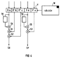
- FIG. 4 A further embodiment of the invention is illustrated with the aid of FIG. 4, which can be used for axes which move continuously in one direction (rotary axes and also linear axes) and which carry out a periodic oscillation as lifting axes is.
- a table chaining device TK is provided at the output of the linking unit for the path control data X ⁇ a , Y ⁇ a of the actual lifting movement.
- the table chaining device TK ensures that the end point is added to the starting point of the previous lifting movement via the summing elements S4 and S5 in the case of a periodic lifting movement as the starting point of the following period. In this way, the necessary description of the movement using a table is limited to one period length.
- the vibration of the continuous movements in amplitude and direction can also be influenced.
- the values of the individual tables can be specifically weighted and combined axially to form an overall movement.
- the new correction option eliminates or reduces the otherwise necessary reloading of the values in the tables when the process parameters change. The most common compromise so far, e.g. in the case of grinding wheel wear, it is no longer necessary to reload the table values when the contour distortions and feed falsifications on the contour are too high.
Abstract
Description
Die Erfindung bezieht sich auf eine Einrichtung zur numerischen Steuerung, insbesondere einer Werkzeugmaschine, wobei eine Zeigerparametrierung für Tabelleninterpolation zur numerischen Bahnsteuerung vorgesehen ist.The invention relates to a device for numerical control, in particular a machine tool, a pointer parameterization for table interpolation for numerical path control being provided.
Die Bearbeitung von Konturen, die nicht durch geometrische Elemente wie Kreis oder Gerade eindeutig zu beschreiben sind, stellt immer schon ein gewisses Problem in der Technik der numerisch gesteuerten Maschinen dar. Im Regelfall werden beliebige Konturen durch möglichst kurze Geradenstücke bzw. Kreisabschnitte angenähert.The processing of contours that cannot be clearly described by geometric elements such as a circle or straight line has always been a certain problem in the technology of numerically controlled machines. As a rule, any contours are approximated by the shortest possible straight line or circle sections.
Die erreichbare Genauigkeit und Bearbeitungsgeschwindigkeit sind durch die Interpolationstaktzeit und die Blockzykluszeit der numerischen Steuerung sowie die einstellbare Kreisverstärkung im Lageregelkreis begrenzt. Zur Abhilfe wurden Steuerungsfunktionen entwickelt, die eine Art elektronisches Kopieren auf Lagerreglerebene möglich machen. Die zu "kopierende" Figur wird in Form einer Tabelle fest um Speicherbereich der numerischen Steuerung abgelegt. Das Laden und die Berechnung der Tabellen wird entweder über ein Teileprogramm der numerischen Steuerung oder direkt über eine V24-Schnittstelle von einem externen Rechner oder einem busgekoppelten Rechner der Steuerung vorgenommen.The achievable accuracy and processing speed are limited by the interpolation cycle time and the block cycle time of the numerical control as well as the adjustable loop gain in the position control loop. To remedy this, control functions have been developed that make it possible to make a kind of electronic copying at the storage controller level. The figure to be "copied" is permanently stored in the form of a table around the memory area of the numerical control. The tables are loaded and calculated either via a part program of the numerical control or directly via a V24 interface from an external computer or a bus-linked computer of the control.
Der Aufbau der Tabelle ist zumeist so, daß der Position einer Basisachse eine feste Sollposition einer Folgeachse zugeordnet wird. Aufgrund des minimalen Rechenaufwandes ist damit eine schnellere Bearbeitung von z.B. Unrundkonturen wie Nockenwellen, Exzentern und Polygonprofilen möglich.The structure of the table is usually such that a fixed target position of a slave axis is assigned to the position of a base axis. Due to the minimal computational effort, faster processing of non-circular contours such as camshafts, eccentrics and polygon profiles is possible.
Die Bearbeitung einer komplexen geometrischen Figur ist mit dieser Art der Tabelleninterpolation entweder überhaupt nicht oder nur bedingt möglich, da hier z.B. dem gleichen Wert der Basisachse mehrere Werte der Folgeachse zugeordnet sein können. Die Auswertung, welcher dieser Punkte gerade seine Gültigkeit hat, kann aber nicht Gegenstand einer schnellen Tabelleninterpolation sein. Ein einfaches Beispiel für eine derartige Möglichkeit, ist z.B. das Abarbeiten eines Vollkreises. Hier sind jedem Wert der X-Basisachse zwei Y-Werte der Folgeachse zugeordnet.With this type of table interpolation, the processing of a complex geometric figure is either not possible at all or only to a limited extent, since here e.g. several values of the following axis can be assigned to the same value of the basic axis. However, the evaluation of which of these points is currently valid cannot be the subject of rapid table interpolation. A simple example of such a possibility is e.g. the processing of a full circle. Here, each value of the X basic axis is assigned two Y values of the following axis.
Eine Lösung des Problems ist im deutschen Gebrauchsmuster G 92 06 933.9 vorgeschlagen. Dort wird, um eine eindeutige Bahnsteuerung für komplexe Bearbeitungsvorgange zu erzielen, eine Zeigerparametrierung vorgesehen, wobei für ausgewählte, vorberechnete Punkte einer zu fahrenden Werkzeugkontur achsspezifische Positionswerte in Tabellenform abgespeichert werden und jeder zusammenhängenden Menge von Positionswerten ein eindimensionaler, achsunabhängiger Zeigerwert zugeordnet wird. Die zu fahrende Bahn sowie die Bahngeschwindigkeit ist dabei durch die vorgegebenen Zeigerwertfolgen und deren Änderungsgeschwindigkeit bestimmt.A solution to the problem is proposed in German utility model G 92 06 933.9. In order to achieve a clear path control for complex machining processes, pointer parameterization is provided, with axis-specific position values being stored in table form for selected, pre-calculated points of a tool contour to be traversed, and a one-dimensional, axis-independent pointer value being assigned to each connected set of position values. The path to be traveled and the path speed are determined by the predefined pointer value sequences and their rate of change.
Bei dieser Lösung war es bisher nicht möglich, eine Werkzeugradiuskorrektur sowie eine Korrektur von verschiedenen Fehlereinflüssen zu erreichen, so daß ein öfteres Umladen der Tabellenwerte bei sich ändernden Prozeßparametern, die beispielsweise durch Werkzeugabnutzung oder durch Temperatureinfluß bedingt sind, notwendig war. Um die dadurch entstandenen Bearbeitungsnebenzeiten möglichst kurz zu halten, wurden bisher beispielsweise bei Schleifmaschinen die Tabellenwerte erst dann umgeladen, wenn die Konturverzerrungen und die Vorschubverfälschungen an der Kontur zu hohe Werte annahmen.With this solution, it was previously not possible to achieve a tool radius correction and a correction of various error influences, so that it was necessary to reload the table values more frequently when the process parameters changed, for example as a result of tool wear or the influence of temperature. In order to keep the resulting processing times as short as possible, the table values for grinders, for example, have only been reloaded until the contour distortions and the feed falsifications on the contour have assumed too high values.
Aufgabe der Erfindung ist es deshalb, das bekannte Verfahren soweit zu verbessern, daß die genannten Nachteile beseitigt werden.The object of the invention is therefore to improve the known method to the extent that the disadvantages mentioned are eliminated.
Dies wird durch ein Verfahren zur numerischen Bahnsteuerung von mehrachsigen Maschinen erreicht, wobei für eine von der Maschine abzufahrende Bahnkurve an ausgewählten und/oder vorberechneten Positionen Bahnsteuerdaten ermittelt und in einem Speicher abgelegt werden, wobei jeder zusammengehörigen Menge von Bahnsteuerdaten ein eindimensionaler Zeiger zugeordnet wird, wobei zur Steuerung der Bahnkurve die Bahnsteuerdaten durch Vorgabe einer Zeigerwertfolge abgerufen werden, wobei jedes Bahnsteuerdatum mit einer Wichtungsgröße verknüpfbar ist und wobei die gewichteten und ungewichteten Bahnsteuerdaten als Stellgrößen an die Bahhsteuervorrichtungen der beteiligten Achsen ausgegeben werden.This is achieved by a method for the numerical path control of multi-axis machines, with path control data being determined for a path curve to be traversed by the machine at selected and / or precalculated positions and being stored in a memory, a one-dimensional pointer being assigned to each associated set of path control data, whereby To control the path curve, the path control data are called up by specifying a pointer value sequence, each path control date being able to be linked to a weighting variable, and the weighted and unweighted path control data being output as manipulated variables to the path control devices of the axes involved.
Das Verfahren laßt sich für periodisch wiederholende Achsbewegungen vorteilhaft anwenden, indem Bahnsteuerdaten mit den zugeordneten Zeigern für eine Periode erstellt werden und die Folgeperioden durch Addition des jeweils letzten Zeigerwertes zum ersten Zeigerwert erzeugt werden. Auf diese Weise wird die notwendige Beschreibung der Bewegung mittels der Tabelle auf eine Periodenlänge begrenzt und die Datenmenge stark reduziert. In Verbindung mit dem vorzeichengerichteten Wichtungsfaktor kann die Schwingung der fortlaufenden Bewegung in Amplitude und Richtung zusätzlich beeinflußt werden.The method can be used advantageously for periodically repeating axis movements by generating path control data with the associated pointers for a period and generating the subsequent periods by adding the respectively last pointer value to the first pointer value. In this way, the necessary description of the movement using the table is limited to a period length and the amount of data is greatly reduced. In conjunction with the sign-oriented weighting factor, the vibration of the continuous movement can also be influenced in amplitude and direction.
Eine weitere vorteilhafte Ausbildung der Erfindung ermöglicht es, jedes Bahnsteuerdatum mit mindestens einem Korrekturwert zu verknüpfen. Damit können geometrische Abweichungen, die beispielsweise durch den Werkstückspanndruck, die Temperatur oder die Last bedingt sind, ausgeglichen werden.A further advantageous embodiment of the invention makes it possible to link each path control data with at least one correction value. Geometric deviations that are caused, for example, by the workpiece clamping pressure, the temperature or the load can thus be compensated.
Da diese Fehlereinflüsse auch abhängig von der Stellung bzw. der laufenden Istposition anderer Achsen sind, wird nach einer weiteren Ausbildung der Erfindung jeweils einer Achse als Basisachse mindestens eine Kompensationsachse zugeordnet, wobei für jede Kombination von Basisachsen und Kompensationsachsen eine Korrekturtabelle gebildet wird. Eine Basisachse kann dabei gleichzeitig ihre eigene Kompensationsachse sein.Since these error influences also depend on the position or the current actual position of other axes, according to a further embodiment of the invention, at least one compensation axis is assigned to each axis as the base axis, a correction table being formed for each combination of base axes and compensation axes. A base axis can also be its own compensation axis.
Die einem Zeiger zugeordneten Bahnsteuerdaten bilden sogenannte Zeigerwerte, die die Positionen der Bahnkurve beschreiben. Wenn zusätzliche Bahnsteuerdaten benötigt werden, die zwischen zwei Zeigerwerten liegen, so können diese durch lineare, zirkulare oder eine andere Interpolationsmethode zwischen zwei aufeinanderfolgenden Zeigerwerten erzeugt werden.The path control data assigned to a pointer form so-called pointer values which describe the positions of the path curve. If additional path control data are required that lie between two pointer values, these can be generated by linear, circular or another interpolation method between two successive pointer values.
Ein Ausführungsbeispiel der Erfindung wird im folgenden anhand der Zeichnung beschrieben. Dabei zeigen:
- FIG 1
- eine mehrdeutige, gekrümmte Kontur mit Zeigerparametrierung,
- FIG 2
- das Blockschaltbild einer Steuerung zur Generierung von Stellgrößen mittels Tabelleninterpolation,
- FIG 3
- ein Werkstückformteil für die Flaschenherstellung,
- FIG 4
- eine Methode zur Tabellenkettung für periodische Achsbewegungen.
- FIG. 1
- an ambiguous, curved contour with pointer parameters,
- FIG 2
- the block diagram of a controller for generating manipulated variables by means of table interpolation,
- FIG 3
- a molded part for bottle production,
- FIG 4
- a method for table chaining for periodic axis movements.
FIG 1 zeigt eine mehrdeutige, gekrümmte Kontur C, wobei die Mehrdeutigkeit darin besteht, das einem Basiswert (X) - wie durch einen Doppelpfeil angedeutet - zwei Hubwerte (Y) zugeordnet sind. Die Kontur C stellt den Querschnitt eines Werkstücks dar, das von einer Schleifscheibe bearbeitet wird. Zur Beschreibung bzw. Parametrierung der Kontur C werden als fiktive Leitgrößen die Zeiger Z1 bis Zn eingeführt, wobei jedem Zeigerwert die entsprechenden Koordinatenwerte als Bahnsteuerdaten X1 bis Xn, Y1 bis Yn zugeordnet und in einer Tabelle H abgelegt werden. Die Tabelle H enthält nun die vorgerechneten bzw. vorgegebenen Bahnsteuerdaten für die Achse 1(X) und die Achse 2(Y), wobei ein Wertepaar X, Y einen bestimmten Punkt der Kontur C beschreibt und damit einer Zeigerposition Z1 bis Zn zugeordnet ist. Aus FIG 1 ist ersichtlich, daß die Zeigerwerte beliebig gewählt bzw. an die Geometrie angepaßt werden können. So sind beispielsweise bei der eiförmigen Kontur C an der stärksten Krümmung die Zeigerwerte besonders eng gelegt, wogegen die Zeigerwerte an den nahezu linearen Teilstücken der Kontur C einen relativ großen Abstand aufweisen. Hierbei sei bemerkt, daß die Zeiger Z1 bis Zn keiner reellen Achse der Maschine entsprechen und somit nicht zur Geometrie der Kontur C beitragen. Ein Zeiger deutet, wie der Name schon sagt, nur auf den momentanen Bearbeitungsort X, Y in der Tabelle hin.1 shows an ambiguous, curved contour C, the ambiguity being that two stroke values (Y) are assigned to a base value (X) - as indicated by a double arrow. The contour C represents the cross section of a workpiece that is processed by a grinding wheel. For describing or parameterizing the contour C, the pointers Z1 to Zn are introduced as fictitious guide variables, each pointer value being assigned the corresponding coordinate values as path control data X1 to Xn, Y1 to Yn and stored in a table H. Table H now contains the precalculated or predefined path control data for axis 1 (X) and axis 2 (Y), a pair of values X, Y describing a specific point on contour C and thus being assigned to a pointer position Z1 to Zn. It can be seen from FIG. 1 that the pointer values can be chosen arbitrarily or can be adapted to the geometry. For example, in the case of the egg-shaped contour C, the pointer values are placed particularly closely at the strongest curvature, whereas the pointer values on the almost linear sections of the contour C are at a relatively large distance. It should be noted here that the pointers Z1 to Zn do not correspond to any real axis of the machine and thus do not contribute to the geometry of the contour C. As the name suggests, a pointer only points to the current processing location X, Y in the table.
In der in FIG 1 gezeigten Tabelle H sind lediglich zwei Bahnsteuerwerte X, Y abgelegt. Die Anzahl der Tabellenspalten kann aber so erweitert werden, daß auch n-dimensionale Bearbeitungen möglich sind. Die Programmierung des Zeigers ZX und damit der Anstoß der Bearbeitung erfolgt im Teileprogramm der numerischen Steuerung, die bei einer realen Achse die Angabe der Zielposition und der Zeigeränderungsgeschwindigkeit beinhaltet. Hierbei ist es auch möglich, den Zeiger mit realen Achsen der Maschine im Interpolationstakt interpolieren zu lassen. Die durch die Tabelleninterpolation selbst bewegten Achsen sind hiervon nicht ausgenommen.Only two path control values X, Y are stored in table H shown in FIG. However, the number of table columns can be expanded so that n-dimensional processing is also possible. The pointer ZX is programmed and the machining is initiated in the part program of the numerical control, which contains the specification of the target position and the pointer change speed for a real axis. It is also possible to have the pointer interpolated with real axes of the machine in the interpolation cycle. The axes themselves moved by the table interpolation are not excluded from this.
Wenn die Kontur C, beispielsweise durch eine Schleifmaschine bearbeitet werden soll, ergeben sich mit zunehmenden Schleifscheibenverschleiß zunehmende Konturverfälschungen, d.h. Abweichungen von den Zeigerpositionen Z1 bis Zn. Bisher wurden diese Abweichungen innerhalb gewisser Grenzen toleriert, und erst bei Überschreitung der vorgegebenen Toleranzen wurden die Tabellenwerte umgeladen, also den Zeigern Z1 bis Zn neue Werte zugeordnet.If the contour C is to be machined, for example by a grinding machine, there is increasing contour distortion with increasing grinding wheel wear, that is to say deviations from the pointer positions Z1 to Zn. So far, these deviations have been tolerated within certain limits and only when the specified values have been exceeded The table values were reloaded to tolerances, i.e. the pointers Z1 to Zn were assigned new values.
Mit der Erfindung läßt sich die Häufigkeit des Umladens der Tabellenwerte stark reduzieren. Es wurde nämlich herausgefunden, daß die Konturverzerrungen und die Vorschubverfälschungen in weiten Bereichen proportional zur Abnahme des Schleifscheibendurchmessers - oder allgemein, zu den Geometrieveränderungen des Werkzeugs sind. Die Bahnsteuerwerte werden daher mit Wichtungsfaktoren a bis e multipliziert, so daß die Konturgenauigkeit innerhalb sehr kleiner Fehlertoleranzen wieder gegeben ist. Auf die Wichtung der Bahnsteuerdaten wird im folgenden anhand von FIG 2 näher eingegangen. Ein weiterer Anwendungsbereich der Wichtungsfaktoren wird weiter unten anhand von FIG 3 erläutert.The frequency of reloading the table values can be greatly reduced with the invention. It has been found that the contour distortions and the feed distortions are largely proportional to the decrease in the grinding wheel diameter - or in general, to the geometry changes of the tool. The path control values are therefore multiplied by weighting factors a to e, so that the contour accuracy is again within very small error tolerances. The weighting of the path control data is discussed in more detail below with the aid of FIG. 2. Another area of application of the weighting factors is explained below with reference to FIG. 3.
FIG 2 zeigt das Blockschaltbild einer Steuerung zur Generierung von Stellgrößen SX, SY für eine Werkzeugmaschine durch Tabelleninterpolation. Es besteht aus einem Interpolator I, Tabellen H, K', K'', einem Lageregler L, einem Wichtungsblock V sowie einer Wichtungstabelle W und Summiergliedern S1 bis S3. Der Speicher H beinhaltet die bereits aus FIG 1 bekannten Tabellenwerte und beschreibt somit die eigentliche Hubkurve der Kontur C (FIG 1).2 shows the block diagram of a controller for generating manipulated variables SX, SY for a machine tool by table interpolation. It consists of an interpolator I, tables H, K ', K' ', a position controller L, a weighting block V and a weighting table W and summing elements S1 to S3. The memory H contains the table values already known from FIG. 1 and thus describes the actual stroke curve of the contour C (FIG. 1).
Anhand der Speicher K' und K'' soll zunächst eine weitere wesentliche Ausbildung der Erfindung erläutert werden. Reale Achsen unterliegen verschiedenen Fehlereinflüssen, die zu einer Abweichung zwischen Ist- und Sollposition führen. Diese Fehler können beispielsweise durch den Werkstückspanndruck, Temperatureinflüsse, die Werkzeug- oder Werkstücklast, etc., hervorgerufen werden. Diese Fehlereinflüsse können nur auf die jeweiligen, an der Bahnbewegung beteiligten Achsen bezogen sein, sie können sich aber auch auf andere Achsen auswirken. Theoretisch sind alle möglichen Kombinationen von Fehlerkopplungen der Achsen untereinander und mit sich selbst denkbar. Im Realfall werden sich die wesentlichen Fehlereinflüsse jedoch auf wenige Achsen reduzieren. Zum Ausgleich dieser Fehler sind in den Speichern K', K'' Korrekturwerte abgelegt, die beispielsweise durch Vermessen der Istwerte bei den entsprechenden Achspositionen ermittelt werden. Diese Bahnsteuerkorrekturwerte X1' bis Xn', Y1' bis Yn' und X1'' bis Xn'' sind ebenfalls in Tabellenform zeigerwertbezogen abgelegt. Prinzipiell werden die Bewegungen der einzelnen Achsen, die an einer Bahn beteiligt sind, in so viele Einzeltabellen H, K', K'' aufgeteilt und hinterlegt, wie es prozeßabhängig zu berücksichtigende Fehlereinflüsse mit unterschiedlicher Korrekturgröße gibt. - Im Ausführungsbeispiel sind im Speicher K'' keine Korrekturwerte für Y'' vorhanden.A further essential embodiment of the invention will first be explained using the memories K 'and K''. Real axes are subject to various influences that lead to a deviation between the actual and target position. These errors can be caused, for example, by the workpiece clamping pressure, temperature influences, the tool or workpiece load, etc. These error influences can only relate to the respective axes involved in the path movement, but they can also affect other axes. In theory, all possible combinations of error coupling of the axes with each other and with themselves are conceivable. In the real case the main influences of errors will be reduced to a few axes. To compensate for these errors, correction values are stored in the memories K ', K'', which are determined, for example, by measuring the actual values at the corresponding axis positions. These path control correction values X1 'to Xn', Y1 'to Yn' and X1 '' to Xn '' are also stored in tabular form in relation to the pointer value. In principle, the movements of the individual axes that are involved in a path are divided and stored in as many individual tables H, K ', K''as there are process-dependent error influences with different correction parameters. - In the exemplary embodiment there are no correction values for Y '' in the memory K ''.
Durch den Interpolator I werden die entsprechenden Zeigerpositionen ZX vorgegeben und somit die entsprechenden Hub- und und Korrekturbahnsteuerdaten aus den Tabellen H, K', K'' ausgelesen und an den Lageregler L übergeben. Von diesem gelangen die Bahnsteuerdaten an die Verknüpfungseinrichtung V in der sie mit den jeweiligen Wichtungsfaktoren a bis e, die aus dem Wichtungsspeicher W ausgelesen werden, verknüpft werden. Die gewichteten Bahnsteuerwerte für die X-Achse, d.h. der gewichtete eigentliche X-Wert X·a und die gewichteten Korrekturwerte X'·b, X''·c werden dann über die Summierglieder S1, S2 zum Stellwert SX addiert, analog dazu wird über den Summierer S3 der Stellwert SY aus ![]()
![]()
Durch die Wichtungsfaktoren a bis e läßt sich aber nicht nur eine Korrektur des Werkzeugs, beispielsweise eines Schleifscheibenverschleisses erreichen, sondern es lassen sich auch durch Modifikation der Wichtungsfaktoren bei gleichbleibenden Bahnsteuerdaten verschiedene Konturformen erzeugen. Dies sei anhand von FIG 3 näher erläutert.The weighting factors a to e can not only be used to correct the tool, for example grinding wheel wear, but also by modifying the weighting factors generate constant contour control data different contour shapes. This will be explained in more detail with reference to FIG 3.
FIG 3 zeigt ein Werkstückformteil für die Flaschenherstellung. Auf dem Bauch der Flasche sollen, über ihren Umfang verteilt, charakteristische Ausprägungen, die die Konturen C1, C2 aufweisen, zu erkennen sein. Die Flaschenform wird durch die Bearbeitung mit der Schleifscheibe S erzielt, indem sich das Werkstück um die Achse A1 dreht und die Schleifscheibe S, die sich um ihre Achse A2 dreht, Zustellbewegungen mit der Achse A3 zum Werkstuck ausfuhrt. In der dargestellten Position der Schleifscheibe S wird das Werkstück an der Querschnittslinie, die durch die Punkte Z1, Z2 verläuft, bearbeitet. Die Punkte Z3, Z4 bzw. Z5, Z6 auf der Kontur C1 lassen sich durch eine Verschiebung der Schleifscheibe entlang der Achse A4 (in negativer X-Richtung) erreichen. Die Bahnsteuerwerte, die die Zeigerwerte Z3, Z4 bzw. Z5, Z6 beinhalten müssen jedoch nicht neu berechnet oder vorgegeben werden, sondern können einfach durch die Verknüpfung der den Zeigerwerten Z1, Z2 zugeordneten Bahnsteuerdaten mit den entsprechenden Wichtungsfaktoren a bis e erzeugt werden. Analog dazu kann die rechts von der Symmetrielinie Z1, Z2 liegende Teilkontur C1 erzeugt werden, indem hier lediglich die Wichtungsfaktoren ein anderes Vorzeichen bekommen.3 shows a workpiece molding for bottle production. Distributed over its circumference, characteristic shapes with the contours C1, C2 should be recognizable on the belly of the bottle. The bottle shape is achieved by machining with the grinding wheel S, in that the workpiece rotates about the axis A1 and the grinding wheel S, which rotates about its axis A2, executes infeed movements with the axis A3 to the workpiece. In the illustrated position of the grinding wheel S, the workpiece is machined on the cross-sectional line that runs through the points Z1, Z2. The points Z3, Z4 or Z5, Z6 on the contour C1 can be achieved by moving the grinding wheel along the axis A4 (in the negative X direction). However, the path control values which contain the pointer values Z3, Z4 or Z5, Z6 do not have to be recalculated or specified, but can be generated simply by linking the path control data assigned to the pointer values Z1, Z2 with the corresponding weighting factors a to e. Analogously to this, the partial contour C1 to the right of the symmetry line Z1, Z2 can be generated by merely giving the weighting factors a different sign.
Mit einer weiteren analogen Anwendung der Wichtungsfaktor-Methode kann die eigentliche Hubkurve einer vorgerechneten Kontur C durch Variation der Vorzeichen einfach geändert werden. Somit können Teile und Konturen mit achsspezifischen Maßstabsfaktoren hergestellt werden und zwar in gleicher Form wie auch nach allen Seiten gespiegelt,With another analog application of the weighting factor method, the actual stroke curve of a pre-calculated contour C can be changed simply by varying the signs. This means that parts and contours can be produced with axis-specific scale factors in the same form and mirrored on all sides,
Anhand von FIG 4 wird eine weitere Ausbildung der Erfindung dargestellt, die für fortlaufend in einer Richtung fahrende Achsen (Rundachsen und auch Linearachsen), die als Hubachsen eine periodische Schwingung ausfuhren, anwendbar ist. Dazu ist am Ausgang der Verknüpfungseinheit bei den Bahnsteuerdaten X·a ,Y·a der eigentlichen Hubbewegung eine Tabellenkettungsvorrichtung TK vorgesehen. Die Tabellenkettungsvorrichtung TK sorgt dafür, daß bei einer periodischen Hubbewegung als Startpunkt der Folgeperiode jeweils der Endpunkt zum Startpunkt der vorhergehenden Hubbewegung über die Summierglieder S4 und S5 addiert wird. Auf diese Weise wird die notwendige Beschreibung der Bewegung mittels Tabelle auf eine Periodenlänge begrenzt. In Verbindung mit den vorzeichengerichteten Wichtungsfaktoren kann die Schwingung der fortlaufenden Bewegungen in Amplitude und Richtung zusätzlich beeinflußt werden.A further embodiment of the invention is illustrated with the aid of FIG. 4, which can be used for axes which move continuously in one direction (rotary axes and also linear axes) and which carry out a periodic oscillation as lifting axes is. For this purpose, a table chaining device TK is provided at the output of the linking unit for the path control data X · a , Y · a of the actual lifting movement. The table chaining device TK ensures that the end point is added to the starting point of the previous lifting movement via the summing elements S4 and S5 in the case of a periodic lifting movement as the starting point of the following period. In this way, the necessary description of the movement using a table is limited to one period length. In conjunction with the sign-oriented weighting factors, the vibration of the continuous movements in amplitude and direction can also be influenced.
Mit dem beschriebenen Verfahren können also die Werte der Einzeltabellen spezifisch gewichtet und achsweise zu einer Gesamtbewegung zusammengefügt werden. Die neue Korrekturmöglichkeit eliminiert bzw. reduziert das sonst notwendige öftere Umladen der Werte in den Tabellen bei sich ändernden Prozeßparametern. Der bisher meistpraktizierte Kompromiß, z.B. beim Schleifscheibenverschleiß die Tabellenwerte erst umzuladen, wenn die Konturverzerrungen und die Vorschubverfälschungen an der Kontur zu hohe Werte annehmen, braucht nicht mehr eingegangen zu werden.With the method described, the values of the individual tables can be specifically weighted and combined axially to form an overall movement. The new correction option eliminates or reduces the otherwise necessary reloading of the values in the tables when the process parameters change. The most common compromise so far, e.g. in the case of grinding wheel wear, it is no longer necessary to reload the table values when the contour distortions and feed falsifications on the contour are too high.
Statt wie bisher üblich jeweils nach einer Durchmesserabnahme der Schleifscheibe um z.B. mehr als 1 % (beispielsweise von 500 auf 495 mm bei neuer Scheibe, von 300 auf 297 mm bei bereits mehrfach abgerichteter Scheibe) die Tabellenwerte umzuladen und im Zwischenbereich mit reiner achsparalleler Korrektur in der Zustellachse zu arbeiten, wird nach dem erfindungsgemäßen Verfahren erst nach einer wesentlich größeren Durchmesserabnahme der Schleifscheibe ein Umladen der Tabellen erforderlich. Die zusätzlich vektoriell wirkende Korrektur die über die Wichtungsfaktoren a bis e an den Schleifscheibenradius anpaßbar ist, bedeutet:
- Gleichbleibende Konturgenauigkeit bei einem sich ändernden Schleifscheibenradius,
- gleichbleibende Vorschubgeschwindigkeit am Kontureingriffspunkt bei jedem Schleifscheibenradius,
- Reduzierung der Bearbeitungsnebenzeiten aufgrund selteneren Umladens der Tabellen.
- Consistent contour accuracy with a changing grinding wheel radius,
- constant feed speed at the contour engagement point for every grinding wheel radius,
- Reduced processing times due to less frequent reloading of the tables.
Claims (5)
Priority Applications (2)
| Application Number | Priority Date | Filing Date | Title |
|---|---|---|---|
| EP19930114778 EP0643343B1 (en) | 1993-09-14 | 1993-09-14 | Numerical contouring control method for multiple axis machines |
| DE59309138T DE59309138D1 (en) | 1993-09-14 | 1993-09-14 | Numerical path control method for multi-axis machines |
Applications Claiming Priority (1)
| Application Number | Priority Date | Filing Date | Title |
|---|---|---|---|
| EP19930114778 EP0643343B1 (en) | 1993-09-14 | 1993-09-14 | Numerical contouring control method for multiple axis machines |
Publications (2)
| Publication Number | Publication Date |
|---|---|
| EP0643343A1 true EP0643343A1 (en) | 1995-03-15 |
| EP0643343B1 EP0643343B1 (en) | 1998-11-18 |
Family
ID=8213259
Family Applications (1)
| Application Number | Title | Priority Date | Filing Date |
|---|---|---|---|
| EP19930114778 Expired - Lifetime EP0643343B1 (en) | 1993-09-14 | 1993-09-14 | Numerical contouring control method for multiple axis machines |
Country Status (2)
| Country | Link |
|---|---|
| EP (1) | EP0643343B1 (en) |
| DE (1) | DE59309138D1 (en) |
Cited By (5)
| Publication number | Priority date | Publication date | Assignee | Title |
|---|---|---|---|---|
| EP0902342A1 (en) * | 1997-09-09 | 1999-03-17 | Axesta Ag | Numerical control for manufacturing non-circular workpieces |
| WO2000039648A1 (en) * | 1998-12-29 | 2000-07-06 | Schneider Automation Inc. | Positional-based motion controller with a bias latch |
| EP1471404A2 (en) * | 2003-04-25 | 2004-10-27 | Star Micronics Co., Ltd. | Numerical control apparatus for machine tool |
| CN103809520A (en) * | 2012-11-12 | 2014-05-21 | 中国科学院沈阳计算技术研究所有限公司 | Full closed-loop control method for multi-shaft linked dynamic correction of interpolation positions |
| CN116184929A (en) * | 2023-04-27 | 2023-05-30 | 湖南隆深氢能科技有限公司 | Intelligent control method and system applied to cutting equipment |
Families Citing this family (1)
| Publication number | Priority date | Publication date | Assignee | Title |
|---|---|---|---|---|
| JP6235457B2 (en) * | 2014-12-25 | 2017-11-22 | ファナック株式会社 | Numerical control device that operates with tabular data |
Citations (7)
| Publication number | Priority date | Publication date | Assignee | Title |
|---|---|---|---|---|
| US3806713A (en) * | 1971-10-21 | 1974-04-23 | Honeywell Inf Systems | Method and apparatus for maximizing the length of straight line segments approximating a curve |
| GB2026725A (en) * | 1978-07-28 | 1980-02-06 | Singer Co | Digital override control of bight and feed in a sewing machine |
| US4343206A (en) * | 1980-06-12 | 1982-08-10 | The United States Of America As Represented By The United States Department Of Energy | Slide system for machine tools |
| GB2146796A (en) * | 1983-08-31 | 1985-04-24 | Mitsubishi Electric Corp | Method for controlling an industrial robot to perform weaving-like motion and apparatus for practising the same |
| US4983899A (en) * | 1988-07-29 | 1991-01-08 | Kabushiki Kaisha Okuma Tekkosho | Numerical control apparatus for controlling a feed shaft and main shaft of a machine tool |
| DE9206933U1 (en) * | 1992-05-21 | 1992-07-16 | Siemens Ag, 8000 Muenchen, De | |
| EP0513417A1 (en) * | 1991-05-16 | 1992-11-19 | Siemens Aktiengesellschaft | Numerical control for machine tool or robot |
-
1993
- 1993-09-14 EP EP19930114778 patent/EP0643343B1/en not_active Expired - Lifetime
- 1993-09-14 DE DE59309138T patent/DE59309138D1/en not_active Expired - Fee Related
Patent Citations (7)
| Publication number | Priority date | Publication date | Assignee | Title |
|---|---|---|---|---|
| US3806713A (en) * | 1971-10-21 | 1974-04-23 | Honeywell Inf Systems | Method and apparatus for maximizing the length of straight line segments approximating a curve |
| GB2026725A (en) * | 1978-07-28 | 1980-02-06 | Singer Co | Digital override control of bight and feed in a sewing machine |
| US4343206A (en) * | 1980-06-12 | 1982-08-10 | The United States Of America As Represented By The United States Department Of Energy | Slide system for machine tools |
| GB2146796A (en) * | 1983-08-31 | 1985-04-24 | Mitsubishi Electric Corp | Method for controlling an industrial robot to perform weaving-like motion and apparatus for practising the same |
| US4983899A (en) * | 1988-07-29 | 1991-01-08 | Kabushiki Kaisha Okuma Tekkosho | Numerical control apparatus for controlling a feed shaft and main shaft of a machine tool |
| EP0513417A1 (en) * | 1991-05-16 | 1992-11-19 | Siemens Aktiengesellschaft | Numerical control for machine tool or robot |
| DE9206933U1 (en) * | 1992-05-21 | 1992-07-16 | Siemens Ag, 8000 Muenchen, De |
Non-Patent Citations (1)
| Title |
|---|
| M. KRAFT ET AL: "Producing Sculptured Curves with CNC", SIEMENS ENERGY & AUTOMATION, vol. 13, no. 6, November 1991 (1991-11-01), BERLIN DE, XP000270305 * |
Cited By (7)
| Publication number | Priority date | Publication date | Assignee | Title |
|---|---|---|---|---|
| EP0902342A1 (en) * | 1997-09-09 | 1999-03-17 | Axesta Ag | Numerical control for manufacturing non-circular workpieces |
| WO2000039648A1 (en) * | 1998-12-29 | 2000-07-06 | Schneider Automation Inc. | Positional-based motion controller with a bias latch |
| EP1471404A2 (en) * | 2003-04-25 | 2004-10-27 | Star Micronics Co., Ltd. | Numerical control apparatus for machine tool |
| EP1471404A3 (en) * | 2003-04-25 | 2005-04-20 | Star Micronics Co., Ltd. | Numerical control apparatus for machine tool |
| CN103809520A (en) * | 2012-11-12 | 2014-05-21 | 中国科学院沈阳计算技术研究所有限公司 | Full closed-loop control method for multi-shaft linked dynamic correction of interpolation positions |
| CN103809520B (en) * | 2012-11-12 | 2017-05-10 | 中国科学院沈阳计算技术研究所有限公司 | Full closed-loop control method for multi-shaft linked dynamic correction of interpolation positions |
| CN116184929A (en) * | 2023-04-27 | 2023-05-30 | 湖南隆深氢能科技有限公司 | Intelligent control method and system applied to cutting equipment |
Also Published As
| Publication number | Publication date |
|---|---|
| EP0643343B1 (en) | 1998-11-18 |
| DE59309138D1 (en) | 1998-12-24 |
Similar Documents
| Publication | Publication Date | Title |
|---|---|---|
| EP1981674A1 (en) | Apparatus and method for machining bevel gears in a pitching method with complete pitch error compensation | |
| DE4023587C2 (en) | Process for the measurement-controlled peripheral grinding of radially non-circular workpieces | |
| DE2422102A1 (en) | NUMERIC CONTROL TO GENERATE A PARABOLIC FLOOR | |
| DE3046363A1 (en) | "POSITION CONTROL SYSTEM WITH A DIGITAL INCREMENTAL MEASURING DEVICE" | |
| DE102004041469B4 (en) | CNC manufacturing arrangement with central database | |
| DE2818058C2 (en) | Bevel cut electrical discharge machine | |
| DE10393527T5 (en) | Systems and methods for displaying complex n-curves for direct control of tool motion | |
| EP0477398B1 (en) | Method to machine workpieces with a numerical controlled machine | |
| DE2338880A1 (en) | METHODS AND DEVICES FOR CONTROLLING THE MOVING PARTS OF A MACHINE TOOL THROUGH A NUMERICAL OUTLINE OR POINT-BY-POINT CONTROL SYSTEM, WHEREAS TWO PARTS OF THE MACHINE INDEPENDENTLY SEPARATE | |
| EP0643343B1 (en) | Numerical contouring control method for multiple axis machines | |
| DE102015012308A1 (en) | Method for producing a workpiece with modified tooth geometry | |
| DE102011108972A1 (en) | Method for controlling e.g. machine tool for machining toothed wheels during hobbing to compensate errors, involves determining sequential axis guide value by calculation specification of parameters, where specification is freely defined | |
| DE2103049C3 (en) | Device of a numerically controlled follow-up system | |
| DE4013617A1 (en) | METHOD FOR CREATING WORK PROGRAMS FOR AUTOMATIC MACHINES | |
| EP0417337B1 (en) | Method for running a digitally controlled machine tool or a robot | |
| EP0563412B1 (en) | Numerical control of machine-tools with interrupt and restart of machining process | |
| DE4430003A1 (en) | Numerical displacement control method for automatic machine tool | |
| DE4326988A1 (en) | Method for controlling machine tools | |
| EP0270060B1 (en) | Numerical control system for highly dynamic processes | |
| DE3908844A1 (en) | Numerical control for machine tools or robots | |
| DE112021005488T5 (en) | NUMERIC CONTROL DEVICE | |
| DE1301222B (en) | Digital program correction device to take into account the cutter diameter for a numerical line control on milling machines | |
| EP0604672A1 (en) | Method for feed-forward torque control of numerically controlled coupled drive systems | |
| DE1812248B2 (en) | Device for driving a moving body and for controlling its current position during its movement | |
| AT404569B (en) | Method and device for mounting and machining crankshafts |
Legal Events
| Date | Code | Title | Description |
|---|---|---|---|
| PUAI | Public reference made under article 153(3) epc to a published international application that has entered the european phase |
Free format text: ORIGINAL CODE: 0009012 |
|
| AK | Designated contracting states |
Kind code of ref document: A1 Designated state(s): CH DE FR IT LI |
|
| 17P | Request for examination filed |
Effective date: 19950404 |
|
| 17Q | First examination report despatched |
Effective date: 19961115 |
|
| GRAG | Despatch of communication of intention to grant |
Free format text: ORIGINAL CODE: EPIDOS AGRA |
|
| GRAG | Despatch of communication of intention to grant |
Free format text: ORIGINAL CODE: EPIDOS AGRA |
|
| GRAH | Despatch of communication of intention to grant a patent |
Free format text: ORIGINAL CODE: EPIDOS IGRA |
|
| GRAH | Despatch of communication of intention to grant a patent |
Free format text: ORIGINAL CODE: EPIDOS IGRA |
|
| GRAA | (expected) grant |
Free format text: ORIGINAL CODE: 0009210 |
|
| AK | Designated contracting states |
Kind code of ref document: B1 Designated state(s): CH DE FR IT LI |
|
| PG25 | Lapsed in a contracting state [announced via postgrant information from national office to epo] |
Ref country code: IT Free format text: LAPSE BECAUSE OF FAILURE TO SUBMIT A TRANSLATION OF THE DESCRIPTION OR TO PAY THE FEE WITHIN THE PRESCRIBED TIME-LIMIT;WARNING: LAPSES OF ITALIAN PATENTS WITH EFFECTIVE DATE BEFORE 2007 MAY HAVE OCCURRED AT ANY TIME BEFORE 2007. THE CORRECT EFFECTIVE DATE MAY BE DIFFERENT FROM THE ONE RECORDED. Effective date: 19981118 Ref country code: FR Free format text: LAPSE BECAUSE OF FAILURE TO SUBMIT A TRANSLATION OF THE DESCRIPTION OR TO PAY THE FEE WITHIN THE PRESCRIBED TIME-LIMIT Effective date: 19981118 |
|
| REG | Reference to a national code |
Ref country code: CH Ref legal event code: EP |
|
| REF | Corresponds to: |
Ref document number: 59309138 Country of ref document: DE Date of ref document: 19981224 |
|
| EN | Fr: translation not filed | ||
| PLBE | No opposition filed within time limit |
Free format text: ORIGINAL CODE: 0009261 |
|
| STAA | Information on the status of an ep patent application or granted ep patent |
Free format text: STATUS: NO OPPOSITION FILED WITHIN TIME LIMIT |
|
| PG25 | Lapsed in a contracting state [announced via postgrant information from national office to epo] |
Ref country code: LI Free format text: LAPSE BECAUSE OF NON-PAYMENT OF DUE FEES Effective date: 19990930 Ref country code: CH Free format text: LAPSE BECAUSE OF NON-PAYMENT OF DUE FEES Effective date: 19990930 |
|
| 26N | No opposition filed | ||
| PGFP | Annual fee paid to national office [announced via postgrant information from national office to epo] |
Ref country code: DE Payment date: 19991118 Year of fee payment: 7 |
|
| REG | Reference to a national code |
Ref country code: CH Ref legal event code: PL |
|
| PG25 | Lapsed in a contracting state [announced via postgrant information from national office to epo] |
Ref country code: DE Free format text: LAPSE BECAUSE OF NON-PAYMENT OF DUE FEES Effective date: 20010601 |