EP0642641B1 - Cryostat assembly - Google Patents
Cryostat assembly Download PDFInfo
- Publication number
- EP0642641B1 EP0642641B1 EP19940909228 EP94909228A EP0642641B1 EP 0642641 B1 EP0642641 B1 EP 0642641B1 EP 19940909228 EP19940909228 EP 19940909228 EP 94909228 A EP94909228 A EP 94909228A EP 0642641 B1 EP0642641 B1 EP 0642641B1
- Authority
- EP
- European Patent Office
- Prior art keywords
- vessel
- assembly according
- support members
- assembly
- points
- Prior art date
- Legal status (The legal status is an assumption and is not a legal conclusion. Google has not performed a legal analysis and makes no representation as to the accuracy of the status listed.)
- Expired - Lifetime
Links
- 230000005484 gravity Effects 0.000 claims abstract description 8
- IJGRMHOSHXDMSA-UHFFFAOYSA-N Atomic nitrogen Chemical compound N#N IJGRMHOSHXDMSA-UHFFFAOYSA-N 0.000 claims description 22
- 239000007788 liquid Substances 0.000 claims description 21
- 239000001307 helium Substances 0.000 claims description 12
- 229910052734 helium Inorganic materials 0.000 claims description 12
- SWQJXJOGLNCZEY-UHFFFAOYSA-N helium atom Chemical compound [He] SWQJXJOGLNCZEY-UHFFFAOYSA-N 0.000 claims description 12
- 239000002826 coolant Substances 0.000 claims description 11
- 229910052757 nitrogen Inorganic materials 0.000 claims description 11
- 229920000271 Kevlar® Polymers 0.000 claims description 3
- 239000003822 epoxy resin Substances 0.000 claims description 3
- 239000004761 kevlar Substances 0.000 claims description 3
- 229920000647 polyepoxide Polymers 0.000 claims description 3
- 238000005481 NMR spectroscopy Methods 0.000 description 5
- 230000000712 assembly Effects 0.000 description 5
- 238000000429 assembly Methods 0.000 description 5
- 238000005259 measurement Methods 0.000 description 3
- 238000004458 analytical method Methods 0.000 description 2
- 230000006866 deterioration Effects 0.000 description 2
- 238000006073 displacement reaction Methods 0.000 description 2
- 230000000694 effects Effects 0.000 description 2
- 239000000725 suspension Substances 0.000 description 2
- 239000003365 glass fiber Substances 0.000 description 1
- 239000000463 material Substances 0.000 description 1
- QJGQUHMNIGDVPM-UHFFFAOYSA-N nitrogen group Chemical group [N] QJGQUHMNIGDVPM-UHFFFAOYSA-N 0.000 description 1
Images
Classifications
-
- F—MECHANICAL ENGINEERING; LIGHTING; HEATING; WEAPONS; BLASTING
- F17—STORING OR DISTRIBUTING GASES OR LIQUIDS
- F17C—VESSELS FOR CONTAINING OR STORING COMPRESSED, LIQUEFIED OR SOLIDIFIED GASES; FIXED-CAPACITY GAS-HOLDERS; FILLING VESSELS WITH, OR DISCHARGING FROM VESSELS, COMPRESSED, LIQUEFIED, OR SOLIDIFIED GASES
- F17C13/00—Details of vessels or of the filling or discharging of vessels
- F17C13/08—Mounting arrangements for vessels
- F17C13/086—Mounting arrangements for vessels for Dewar vessels or cryostats
- F17C13/087—Mounting arrangements for vessels for Dewar vessels or cryostats used for superconducting phenomena
-
- G—PHYSICS
- G01—MEASURING; TESTING
- G01R—MEASURING ELECTRIC VARIABLES; MEASURING MAGNETIC VARIABLES
- G01R33/00—Arrangements or instruments for measuring magnetic variables
- G01R33/20—Arrangements or instruments for measuring magnetic variables involving magnetic resonance
- G01R33/28—Details of apparatus provided for in groups G01R33/44 - G01R33/64
- G01R33/38—Systems for generation, homogenisation or stabilisation of the main or gradient magnetic field
- G01R33/381—Systems for generation, homogenisation or stabilisation of the main or gradient magnetic field using electromagnets
- G01R33/3815—Systems for generation, homogenisation or stabilisation of the main or gradient magnetic field using electromagnets with superconducting coils, e.g. power supply therefor
-
- F—MECHANICAL ENGINEERING; LIGHTING; HEATING; WEAPONS; BLASTING
- F17—STORING OR DISTRIBUTING GASES OR LIQUIDS
- F17C—VESSELS FOR CONTAINING OR STORING COMPRESSED, LIQUEFIED OR SOLIDIFIED GASES; FIXED-CAPACITY GAS-HOLDERS; FILLING VESSELS WITH, OR DISCHARGING FROM VESSELS, COMPRESSED, LIQUEFIED, OR SOLIDIFIED GASES
- F17C2201/00—Vessel construction, in particular geometry, arrangement or size
- F17C2201/01—Shape
- F17C2201/0104—Shape cylindrical
- F17C2201/0119—Shape cylindrical with flat end-piece
-
- F—MECHANICAL ENGINEERING; LIGHTING; HEATING; WEAPONS; BLASTING
- F17—STORING OR DISTRIBUTING GASES OR LIQUIDS
- F17C—VESSELS FOR CONTAINING OR STORING COMPRESSED, LIQUEFIED OR SOLIDIFIED GASES; FIXED-CAPACITY GAS-HOLDERS; FILLING VESSELS WITH, OR DISCHARGING FROM VESSELS, COMPRESSED, LIQUEFIED, OR SOLIDIFIED GASES
- F17C2203/00—Vessel construction, in particular walls or details thereof
- F17C2203/06—Materials for walls or layers thereof; Properties or structures of walls or their materials
- F17C2203/0602—Wall structures; Special features thereof
- F17C2203/0612—Wall structures
- F17C2203/0626—Multiple walls
- F17C2203/0629—Two walls
-
- F—MECHANICAL ENGINEERING; LIGHTING; HEATING; WEAPONS; BLASTING
- F17—STORING OR DISTRIBUTING GASES OR LIQUIDS
- F17C—VESSELS FOR CONTAINING OR STORING COMPRESSED, LIQUEFIED OR SOLIDIFIED GASES; FIXED-CAPACITY GAS-HOLDERS; FILLING VESSELS WITH, OR DISCHARGING FROM VESSELS, COMPRESSED, LIQUEFIED, OR SOLIDIFIED GASES
- F17C2223/00—Handled fluid before transfer, i.e. state of fluid when stored in the vessel or before transfer from the vessel
- F17C2223/01—Handled fluid before transfer, i.e. state of fluid when stored in the vessel or before transfer from the vessel characterised by the phase
- F17C2223/0146—Two-phase
- F17C2223/0153—Liquefied gas, e.g. LPG, GPL
- F17C2223/0161—Liquefied gas, e.g. LPG, GPL cryogenic, e.g. LNG, GNL, PLNG
-
- F—MECHANICAL ENGINEERING; LIGHTING; HEATING; WEAPONS; BLASTING
- F17—STORING OR DISTRIBUTING GASES OR LIQUIDS
- F17C—VESSELS FOR CONTAINING OR STORING COMPRESSED, LIQUEFIED OR SOLIDIFIED GASES; FIXED-CAPACITY GAS-HOLDERS; FILLING VESSELS WITH, OR DISCHARGING FROM VESSELS, COMPRESSED, LIQUEFIED, OR SOLIDIFIED GASES
- F17C2270/00—Applications
- F17C2270/05—Applications for industrial use
- F17C2270/0509—"Dewar" vessels
Definitions
- the invention relates to a cryostat assembly.
- Cryostat assemblies are used in a variety of fields to provide a cooled region within which is positioned an instrument such as a detector or a magnet particularly where it is desired to provide a superconducting magnet.
- cryostats are susceptible to low frequency vibrations which, in the case for example of a spectrometer, can lead to deterioration in the accuracy of the results which are obtained.
- the reason for the deterioration is that the time varying perturbation of the magnetic field on the nuclear magnetic resonance (NMR) or ion cyclotron resonance (ICR) sample which results from the vibrations will lead to undesirable artifacts in the measurements made.
- US-A-4721934 describes a horizontally oriented cryostat suspension system in which a helium vessel is supported by a vacuum vessel via a number of radial and axial straps.
- a cryostat assembly comprising an inner vessel for containing an item to be cooled, characterised in that the inner vessel has a substantially uprightly oriented bore, and in that the inner vessel is suspended from the outer vessel by a number of low thermal conductivity support members secured at one end to points on the outer vessel substantially at the height of the centre of gravity of the system constituted by the assembly and item in use and at the other end to the inner vessel at points not higher than the said points on the outer vessel.
- the one ends of the support members do not need to exactly align with the centre of gravity of the system, and for example the one ends of the support members may be secured to the outer vessel at points situated within 10% of the overall height of the assembly above or below a horizontal plane containing the centre of gravity.
- the other ends of the support members will be connected to the base of the inner vessel but in principle other secure points are possible.
- the fixing point to the vessel should, as far as vibration reduction is concerned, be strong, therefore the corner of the vessel, or a rigidly supported part of it, would be best. Since the base of a typical Helium vessel is thick, this would be a good point of attachment.
- the cryostat assembly may comprise just the outer vessel and the inner vessel. Normally, however, additional vessels and/or thermal shields are provided.
- the inner vessel comprises a first coolant containing vessel, the assembly further comprising a second coolant containing vessel surrounding the first and suspended from the outer vessel, and optionally a thermal shield surrounding the first coolant vessel and suspended from the second coolant vessel.
- the magnet In the case where the assembly is to be used to cool a superconducting magnet, the magnet will be placed in the inner vessel with the first coolant typically being liquid Helium, while the second coolant is liquid nitrogen.
- support members suspending the inner vessel from the outer vessel.
- the ends of the support members attached to the outer vacuum vessel may be attached via a continuous ring or by individual mounting arrangements.
- low conductivity is well understood in the art, a typical example being 170 watts/metre.
- the support members could comprise glass fibre reinforced epoxy resin rods but in the preferred arrangement comprise Kevlar reinforced epoxy resin rods.
- the modulus of elasticity of this material is higher giving a stiffer suspension system, raising the resonance frequencies and reducing the magnet displacements.
- Cryostat assemblies according to the invention can be used, for example, to house magnets for use in nuclear magnetic resonance applications and ion cyclotron resonance applications.
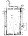
- cryostat assembly for use in an NMR spectrometer will now be described with reference to the accompanying drawing which is a longitudinal section through the cryostat assembly.
- the assembly comprises an outer vacuum vessel 1 having a tubular form with a domed top portion and defining an internal volume which is evacuated in use. Nested within the outer vacuum vessel 1 are a liquid nitrogen vessel 2 having liquid nitrogen containing portion 3, a thermal shield 4, and a liquid helium vessel 5 which contains liquid helium. Each of the vessels 2,5 and the thermal shield 4 is tubular.
- the outer vacuum vessel 1, and the vessels 2,5 each have a vertically oriented bore defined by a respective tube 6,7,8.
- An electromagnet 9 is mounted within the helium vessel 5 about the tube 8 and will generate a high strength magnetic field having a homogeneous, working region centred at an origin 10 within the tube 6.
- the cryostat has a neck section 11 at the top, of generally conventional form, including an outer section 12 communicating with the outer vacuum vessel 1, and an inner section 13 to enable the liquid helium to be supplied to the liquid helium vessel 5.
- the cryostat has a further neck section 14 including an outer section 15 communicating with the outer vacuum vessel 1, and an inner section 16 to enable the liquid nitrogen to be supplied to the nitrogen vessel 3.
- the liquid nitrogen vessel, liquid helium vessel and the thermal shield are all suspended from the domed portion of the vacuum vessel.
- the inner, liquid helium vessel 5 is suspended from the outer vacuum vessel 1 by a set of three Kevlar rods 17 (only one visible in the drawing) which are secured at one end 18 to a bracket 19 mounted to the base of the liquid helium vessel 5, pass through apertures in the thermal shield 4 and liquid nitrogen vessel 2 and are anchored at their other end 20 to the outer vacuum vessel 1.
- the position of the anchorage 20 is chosen to be substantially in a plane orthogonal to the vertical axis and containing the centre of gravity of the magnet and cryostat. Variations from this position within about 10% of the height of the cryostat are possible without seriously affecting the resonant frequencies.
- the liquid nitrogen vessel 2 is suspended from the outer vacuum vessel 1 by a set of three substantially equally angularly spaced rods 21 (only one shown in the drawing) extending from an upper end of the outer vacuum vessel 1 at a mounting 22 to a bracket 23 connected to the liquid nitrogen vessel.
- the thermal shield 4 is suspended from the liquid nitrogen vessel by a set of three substantially equally angularly spaced support rods 24 (only one shown in the drawing) extending from an upper surface 25 of the liquid nitrogen vessel to a bracket 26 on the thermal shield.
Landscapes
- Physics & Mathematics (AREA)
- Engineering & Computer Science (AREA)
- Electromagnetism (AREA)
- Condensed Matter Physics & Semiconductors (AREA)
- General Physics & Mathematics (AREA)
- Mechanical Engineering (AREA)
- General Engineering & Computer Science (AREA)
- Magnetic Resonance Imaging Apparatus (AREA)
- Containers, Films, And Cooling For Superconductive Devices (AREA)
- Filling Or Discharging Of Gas Storage Vessels (AREA)
Abstract
Description
- The invention relates to a cryostat assembly. Cryostat assemblies are used in a variety of fields to provide a cooled region within which is positioned an instrument such as a detector or a magnet particularly where it is desired to provide a superconducting magnet.
- One of the problems with conventional cryostats is that they are susceptible to low frequency vibrations which, in the case for example of a spectrometer, can lead to deterioration in the accuracy of the results which are obtained. The reason for the deterioration is that the time varying perturbation of the magnetic field on the nuclear magnetic resonance (NMR) or ion cyclotron resonance (ICR) sample which results from the vibrations will lead to undesirable artifacts in the measurements made.
- US-A-4721934 describes a horizontally oriented cryostat suspension system in which a helium vessel is supported by a vacuum vessel via a number of radial and axial straps.
- In accordance with the present invention there is provided a cryostat assembly comprising an inner vessel for containing an item to be cooled, characterised in that the inner vessel has a substantially uprightly oriented bore, and in that the inner vessel is suspended from the outer vessel by a number of low thermal conductivity support members secured at one end to points on the outer vessel substantially at the height of the centre of gravity of the system constituted by the assembly and item in use and at the other end to the inner vessel at points not higher than the said points on the outer vessel.
- We have realised that conventional assemblies arrange for the various vessels to be supported towards the top from the outer, usually vacuum, vessel leading to a "pendulum" effect in response to low vibration input. In contrast, the invention arranges for the inner vessel to be suspended from the outer vessel from points between the ends of the outer vessel, typically substantially mid-way along the outer vessel substantially in line with the centre of gravity of the system. A modal analysis of an assembly constructed according to the invention has shown that the lowest modal frequencies are significantly higher with the invention than those obtained with conventional assemblies.
- In practice, the one ends of the support members do not need to exactly align with the centre of gravity of the system, and for example the one ends of the support members may be secured to the outer vessel at points situated within 10% of the overall height of the assembly above or below a horizontal plane containing the centre of gravity.
- Typically, the other ends of the support members will be connected to the base of the inner vessel but in principle other secure points are possible. In general, the fixing point to the vessel should, as far as vibration reduction is concerned, be strong, therefore the corner of the vessel, or a rigidly supported part of it, would be best. Since the base of a typical Helium vessel is thick, this would be a good point of attachment.
- In some cases, the cryostat assembly may comprise just the outer vessel and the inner vessel. Normally, however, additional vessels and/or thermal shields are provided. In the preferred arrangement, the inner vessel comprises a first coolant containing vessel, the assembly further comprising a second coolant containing vessel surrounding the first and suspended from the outer vessel, and optionally a thermal shield surrounding the first coolant vessel and suspended from the second coolant vessel.
- In the case where the assembly is to be used to cool a superconducting magnet, the magnet will be placed in the inner vessel with the first coolant typically being liquid Helium, while the second coolant is liquid nitrogen.
- Typically, there will be three substantially equally angularly spaced support members suspending the inner vessel from the outer vessel. The ends of the support members attached to the outer vacuum vessel may be attached via a continuous ring or by individual mounting arrangements.
- The term "low conductivity" is well understood in the art, a typical example being 170 watts/metre.
- The support members could comprise glass fibre reinforced epoxy resin rods but in the preferred arrangement comprise Kevlar reinforced epoxy resin rods. The modulus of elasticity of this material is higher giving a stiffer suspension system, raising the resonance frequencies and reducing the magnet displacements.
- Although magnet displacements are smaller at higher frequencies, and therefore higher frequency vibrations are less of a problem as regards this, it is possible to get resonance artefacts in the spectrometer results which are in the higher frequency range. It would be possible to support the cryostat assembly on an anti-vibration mounting which prevents frequencies higher than the lowest modal frequency from being communicated to the cryostat assembly. In this way the assembly could be completely isolated from the effects of vibration.
- Cryostat assemblies according to the invention can be used, for example, to house magnets for use in nuclear magnetic resonance applications and ion cyclotron resonance applications.
- An example of a cryostat assembly according to the invention for use in an NMR spectrometer will now be described with reference to the accompanying drawing which is a longitudinal section through the cryostat assembly.
- The assembly comprises an
outer vacuum vessel 1 having a tubular form with a domed top portion and defining an internal volume which is evacuated in use. Nested within theouter vacuum vessel 1 are aliquid nitrogen vessel 2 having liquidnitrogen containing portion 3, a thermal shield 4, and aliquid helium vessel 5 which contains liquid helium. Each of thevessels outer vacuum vessel 1, and thevessels respective tube - An electromagnet 9 is mounted within the
helium vessel 5 about the tube 8 and will generate a high strength magnetic field having a homogeneous, working region centred at anorigin 10 within thetube 6. - The cryostat has a
neck section 11 at the top, of generally conventional form, including anouter section 12 communicating with theouter vacuum vessel 1, and aninner section 13 to enable the liquid helium to be supplied to theliquid helium vessel 5. The cryostat has afurther neck section 14 including an outer section 15 communicating with theouter vacuum vessel 1, and an inner section 16 to enable the liquid nitrogen to be supplied to thenitrogen vessel 3. - Conventionally, the liquid nitrogen vessel, liquid helium vessel and the thermal shield are all suspended from the domed portion of the vacuum vessel. In the present case, however, the inner,
liquid helium vessel 5 is suspended from theouter vacuum vessel 1 by a set of three Kevlar rods 17 (only one visible in the drawing) which are secured at oneend 18 to abracket 19 mounted to the base of theliquid helium vessel 5, pass through apertures in the thermal shield 4 andliquid nitrogen vessel 2 and are anchored at theirother end 20 to theouter vacuum vessel 1. The position of theanchorage 20 is chosen to be substantially in a plane orthogonal to the vertical axis and containing the centre of gravity of the magnet and cryostat. Variations from this position within about 10% of the height of the cryostat are possible without seriously affecting the resonant frequencies. - The
liquid nitrogen vessel 2 is suspended from theouter vacuum vessel 1 by a set of three substantially equally angularly spaced rods 21 (only one shown in the drawing) extending from an upper end of theouter vacuum vessel 1 at amounting 22 to abracket 23 connected to the liquid nitrogen vessel. - The thermal shield 4 is suspended from the liquid nitrogen vessel by a set of three substantially equally angularly spaced support rods 24 (only one shown in the drawing) extending from an
upper surface 25 of the liquid nitrogen vessel to abracket 26 on the thermal shield. - In order to see the improvement in modal frequency response which is achieved using the cryostat assembly shown in the drawing as compared with the conventional cryostat assembly in which all the vessels and shields are supported from the dome portion of the outer vacuum vessel, a finite element analysis has been carried out on the conventional and the new assemblies of similar size and specification. The modal frequencies obtained are set out in the table below.
TABLE MODE MODAL FREQUENCIES (Hz) CONVENTIONAL NEW 1 1.54 15.36 2 1.54 17.44 3 2.58 30.3 4 4.01 30.6 5 4.15 35.2 6 4.12 42.9 7 5.97 44.6 8 7.89 44.6 9 15.13 44.6 10 18.03 44.6 11 25.70 44.6 12 29.81 47.9 13 34.17 47.9 14 34.92 50.0 - It can be seen from the Table that the lowest modal frequencies of the new assembly are considerably higher than those of the conventional assembly and this leads to a far more stable cryostat which is not susceptible to external, low frequency vibrations and thus reduces the occurrence of undesirable artifacts in the NMR (or ICR) measurements, in comparison with the measurements obtained using a conventional assembly.
Claims (11)
- A cryostat assembly comprising an outer vessel within which is provided an inner vessel for containing an item to be cooled, characterised in that the inner vessel has a substantially uprightly oriented bore, and in that the inner vessel is suspended from the outer vessel by a number of low thermal conductivity support members secured at one end to points on the outer vessel substantially at the height of the centre of gravity of the system constituted by the assembly and item in use and at the other end to the inner vessel at points not higher than the said points on the outer vessel.
- An assembly according to claim 1, wherein the one ends of the support members are secured to the outer vessel at points situated within 10% of the overall height of the assembly above or below a horizontal plane containing the centre of gravity.
- An assembly according to claim 1 or claim 2, wherein the one ends of the support members are positioned substantially in the same horizontal plane.
- An assembly according to any of claims 1 to 3, wherein three support members are provided substantially equally angularly spaced around the outer vessel.
- An assembly according to any of the preceding claims, wherein the support members comprise Kevlar reinforced, epoxy resin rods.
- An assembly according to any of the preceding claims, wherein the outer vessel is evacuated in use, and the inner vessel comprises a liquid coolant containing vessel.
- An assembly according to claim 6, further comprising a second coolant containing vessel surrounding the inner vessel, and a thermal shield surrounding the second coolant containing vessel.
- An assembly according to claim 7, wherein the inner coolant containing vessel contains liquid helium in use, and the second coolant containing vessel contains liquid nitrogen in use.
- An assembly according to any of the preceding claims, further comprising an electromagnet situated in the inner vessel.
- An NMR spectrometer or ion cyclotron resonance device including a cryostat assembly according to any of the preceding claims.
- An assembly according to any of claims 1 to 9 or an NMR spectrometer or ion cyclotron device according to claim 10, wherein said inner vessel is suspended from the outer vessel solely by said support members, each of said support members being in tension.
Applications Claiming Priority (3)
| Application Number | Priority Date | Filing Date | Title |
|---|---|---|---|
| GB9306166 | 1993-03-25 | ||
| GB9306166A GB9306166D0 (en) | 1993-03-25 | 1993-03-25 | Cryostat assembly |
| PCT/GB1994/000523 WO1994021956A1 (en) | 1993-03-25 | 1994-03-16 | Cryostat assembly |
Publications (2)
| Publication Number | Publication Date |
|---|---|
| EP0642641A1 EP0642641A1 (en) | 1995-03-15 |
| EP0642641B1 true EP0642641B1 (en) | 1996-12-27 |
Family
ID=10732700
Family Applications (1)
| Application Number | Title | Priority Date | Filing Date |
|---|---|---|---|
| EP19940909228 Expired - Lifetime EP0642641B1 (en) | 1993-03-25 | 1994-03-16 | Cryostat assembly |
Country Status (6)
| Country | Link |
|---|---|
| US (1) | US5537829A (en) |
| EP (1) | EP0642641B1 (en) |
| JP (1) | JPH07507878A (en) |
| DE (1) | DE69401251T2 (en) |
| GB (1) | GB9306166D0 (en) |
| WO (1) | WO1994021956A1 (en) |
Cited By (1)
| Publication number | Priority date | Publication date | Assignee | Title |
|---|---|---|---|---|
| US7040099B2 (en) | 2001-11-21 | 2006-05-09 | Siemens Aktiengesellschaft | Cryostat |
Families Citing this family (10)
| Publication number | Priority date | Publication date | Assignee | Title |
|---|---|---|---|---|
| US6411087B1 (en) | 1999-05-17 | 2002-06-25 | University Of Houston | NMR logging tool with Hi-Tc trap field magnet |
| US6487866B1 (en) | 2000-07-10 | 2002-12-03 | The United States Of America As Represented By The National Aeronautics & Space Administration | Multipurpose thermal insulation test apparatus |
| US6742926B1 (en) | 2000-07-10 | 2004-06-01 | The United States Of America As Represented By The Administrator Of The National Aeronautics And Space Administration | Methods of testing thermal insulation and associated test apparatus |
| DE10128516A1 (en) * | 2001-06-13 | 2002-12-19 | Linde Ag | Storage containers for cryogenic media |
| GB0121603D0 (en) * | 2001-09-06 | 2001-10-24 | Oxford Instr Superconductivity | Magnet assembly |
| DE10251449B4 (en) | 2001-11-21 | 2004-12-30 | Siemens Ag | cryostat |
| DE10345958A1 (en) * | 2003-10-02 | 2005-04-21 | Magna Steyr Fahrzeugtechnik Ag | Mobile tank for cryogenic liquids |
| GB2449652B (en) * | 2007-05-30 | 2009-06-10 | Siemens Magnet Technology Ltd | Suspension rod tensioning arrangements |
| US11099247B2 (en) | 2012-01-27 | 2021-08-24 | Bruker Biospin Corporation | Ultra-low vibration cryogen-free cryostat for an electron paramagnetic resonance system |
| US9390875B2 (en) * | 2013-05-29 | 2016-07-12 | Active Signal Technologies, Inc. | Electromagnetic opposing field actuators |
Family Cites Families (9)
| Publication number | Priority date | Publication date | Assignee | Title |
|---|---|---|---|---|
| US2863297A (en) * | 1955-03-29 | 1958-12-09 | Herrick L Johnston Inc | Method and apparatus for storing liquified gases |
| FR1190831A (en) * | 1958-01-28 | 1959-10-15 | Air Liquide | Cables resilient at very low temperatures |
| DE1814783C3 (en) * | 1968-12-14 | 1975-08-28 | Siemens Ag, 1000 Berlin Und 8000 Muenchen | Cryostat with a superconducting coil arranged in a container for a low-boiling liquid coolant |
| US3782128A (en) * | 1970-06-01 | 1974-01-01 | Lox Equip | Cryogenic storage vessel |
| US4038832A (en) * | 1975-09-08 | 1977-08-02 | Beatrice Foods Co. | Liquefied gas container of large capacity |
| US4721934A (en) * | 1987-04-02 | 1988-01-26 | General Electric Company | Axial strap suspension system for a magnetic resonance magnet |
| CA1319263C (en) * | 1989-04-03 | 1993-06-22 | Roy C. Reid | Support system for vacuum insulated cylindrical cryogenic vessels |
| JPH0334404A (en) * | 1989-06-30 | 1991-02-14 | Mitsubishi Electric Corp | Cryogenic refrigerator |
| JPH05178378A (en) * | 1991-12-26 | 1993-07-20 | Mitsubishi Heavy Ind Ltd | Vibration resisting double wall heat insulating container |
-
1993
- 1993-03-25 GB GB9306166A patent/GB9306166D0/en active Pending
-
1994
- 1994-03-16 DE DE69401251T patent/DE69401251T2/en not_active Expired - Fee Related
- 1994-03-16 EP EP19940909228 patent/EP0642641B1/en not_active Expired - Lifetime
- 1994-03-16 JP JP6520777A patent/JPH07507878A/en active Pending
- 1994-03-16 WO PCT/GB1994/000523 patent/WO1994021956A1/en not_active Ceased
- 1994-03-16 US US08/360,827 patent/US5537829A/en not_active Expired - Fee Related
Cited By (1)
| Publication number | Priority date | Publication date | Assignee | Title |
|---|---|---|---|---|
| US7040099B2 (en) | 2001-11-21 | 2006-05-09 | Siemens Aktiengesellschaft | Cryostat |
Also Published As
| Publication number | Publication date |
|---|---|
| EP0642641A1 (en) | 1995-03-15 |
| JPH07507878A (en) | 1995-08-31 |
| US5537829A (en) | 1996-07-23 |
| WO1994021956A1 (en) | 1994-09-29 |
| DE69401251T2 (en) | 1997-06-19 |
| DE69401251D1 (en) | 1997-02-06 |
| GB9306166D0 (en) | 1993-05-19 |
Similar Documents
| Publication | Publication Date | Title |
|---|---|---|
| US6181228B1 (en) | Superconductive magnet including a cryocooler coldhead | |
| US5793210A (en) | Low noise MRI scanner | |
| US8028853B2 (en) | Cryostat comprising a cryogen vessel suspended within an outer vacuum container | |
| EP0817211B1 (en) | Superconducting magnet device and magnetic resonance imaging device using the same | |
| US6157276A (en) | MRI magnet assembly with non-conductive inner wall | |
| US5537829A (en) | Cryostat assembly | |
| EP0837339A1 (en) | Planar superconducting MRI magnet | |
| US7227437B2 (en) | High field open MRI magnet isolation system and method | |
| US5237300A (en) | Support structure for actively shielded superconducting magnets | |
| US5574417A (en) | Open MRI magnet with homogeneous imaging volume | |
| US5721523A (en) | Compact MRI superconducting magnet | |
| US6100780A (en) | Cryogenic-fluid-cooled open MRI magnet with uniform magnetic field | |
| CN107204226B (en) | Low-temperature container of superconducting magnet | |
| US5864273A (en) | Cryocooler vibration isolation and noise reduction in magnetic resonance imaging | |
| US6201462B1 (en) | Open superconductive magnet having a cryocooler coldhead | |
| US5345208A (en) | Pole face design for a C-shaped superconducting magnet | |
| US20080315878A1 (en) | Actively Shielded Gradient Coil System Comprising Additional Additional Eddy Current Shield System | |
| US6198371B1 (en) | Open magnet with floor mount | |
| CN110082695A (en) | Superconducting magnet and magnetic resonance imaging system with the superconducting magnet | |
| US7126448B2 (en) | Superconducting magnet apparatus and magnetic resonance imaging apparatus using the same | |
| CN114724796A (en) | Magnetic resonance superconducting magnet with novel structure | |
| JP2007000254A (en) | Superconducting electromagnet device for MRI | |
| US4853661A (en) | Superconducting magnet with separate support system | |
| US20050122106A1 (en) | Gradient coil arrangement | |
| EP1324064B1 (en) | High field open magnetic resonance magnet with reduced vibration |
Legal Events
| Date | Code | Title | Description |
|---|---|---|---|
| PUAI | Public reference made under article 153(3) epc to a published international application that has entered the european phase |
Free format text: ORIGINAL CODE: 0009012 |
|
| 17P | Request for examination filed |
Effective date: 19941003 |
|
| AK | Designated contracting states |
Kind code of ref document: A1 Designated state(s): CH DE FR GB LI NL |
|
| 17Q | First examination report despatched |
Effective date: 19951012 |
|
| GRAG | Despatch of communication of intention to grant |
Free format text: ORIGINAL CODE: EPIDOS AGRA |
|
| GRAH | Despatch of communication of intention to grant a patent |
Free format text: ORIGINAL CODE: EPIDOS IGRA |
|
| GRAH | Despatch of communication of intention to grant a patent |
Free format text: ORIGINAL CODE: EPIDOS IGRA |
|
| GRAA | (expected) grant |
Free format text: ORIGINAL CODE: 0009210 |
|
| AK | Designated contracting states |
Kind code of ref document: B1 Designated state(s): CH DE FR GB LI NL |
|
| REG | Reference to a national code |
Ref country code: CH Ref legal event code: NV Representative=s name: ISLER & PEDRAZZINI AG |
|
| REF | Corresponds to: |
Ref document number: 69401251 Country of ref document: DE Date of ref document: 19970206 |
|
| ET | Fr: translation filed | ||
| PLBE | No opposition filed within time limit |
Free format text: ORIGINAL CODE: 0009261 |
|
| STAA | Information on the status of an ep patent application or granted ep patent |
Free format text: STATUS: NO OPPOSITION FILED WITHIN TIME LIMIT |
|
| 26N | No opposition filed | ||
| REG | Reference to a national code |
Ref country code: GB Ref legal event code: IF02 |
|
| PGFP | Annual fee paid to national office [announced via postgrant information from national office to epo] |
Ref country code: FR Payment date: 20030310 Year of fee payment: 10 |
|
| PGFP | Annual fee paid to national office [announced via postgrant information from national office to epo] |
Ref country code: CH Payment date: 20030314 Year of fee payment: 10 |
|
| PGFP | Annual fee paid to national office [announced via postgrant information from national office to epo] |
Ref country code: NL Payment date: 20030327 Year of fee payment: 10 |
|
| PG25 | Lapsed in a contracting state [announced via postgrant information from national office to epo] |
Ref country code: LI Free format text: LAPSE BECAUSE OF NON-PAYMENT OF DUE FEES Effective date: 20040331 Ref country code: CH Free format text: LAPSE BECAUSE OF NON-PAYMENT OF DUE FEES Effective date: 20040331 |
|
| PG25 | Lapsed in a contracting state [announced via postgrant information from national office to epo] |
Ref country code: NL Free format text: LAPSE BECAUSE OF NON-PAYMENT OF DUE FEES Effective date: 20041001 |
|
| REG | Reference to a national code |
Ref country code: CH Ref legal event code: PL |
|
| PG25 | Lapsed in a contracting state [announced via postgrant information from national office to epo] |
Ref country code: FR Free format text: LAPSE BECAUSE OF NON-PAYMENT OF DUE FEES Effective date: 20041130 |
|
| NLV4 | Nl: lapsed or anulled due to non-payment of the annual fee |
Effective date: 20041001 |
|
| REG | Reference to a national code |
Ref country code: FR Ref legal event code: ST |
|
| PGFP | Annual fee paid to national office [announced via postgrant information from national office to epo] |
Ref country code: DE Payment date: 20060309 Year of fee payment: 13 |
|
| PGFP | Annual fee paid to national office [announced via postgrant information from national office to epo] |
Ref country code: GB Payment date: 20060315 Year of fee payment: 13 |
|
| GBPC | Gb: european patent ceased through non-payment of renewal fee |
Effective date: 20070316 |
|
| PG25 | Lapsed in a contracting state [announced via postgrant information from national office to epo] |
Ref country code: DE Free format text: LAPSE BECAUSE OF NON-PAYMENT OF DUE FEES Effective date: 20071002 |
|
| PG25 | Lapsed in a contracting state [announced via postgrant information from national office to epo] |
Ref country code: GB Free format text: LAPSE BECAUSE OF NON-PAYMENT OF DUE FEES Effective date: 20070316 |