EP0641920B1 - Malfunction diagnosis apparatus for internal combustion engine - Google Patents
Malfunction diagnosis apparatus for internal combustion engine Download PDFInfo
- Publication number
- EP0641920B1 EP0641920B1 EP94114042A EP94114042A EP0641920B1 EP 0641920 B1 EP0641920 B1 EP 0641920B1 EP 94114042 A EP94114042 A EP 94114042A EP 94114042 A EP94114042 A EP 94114042A EP 0641920 B1 EP0641920 B1 EP 0641920B1
- Authority
- EP
- European Patent Office
- Prior art keywords
- malfunction
- catalyst
- deterioration
- internal combustion
- combustion engine
- Prior art date
- Legal status (The legal status is an assumption and is not a legal conclusion. Google has not performed a legal analysis and makes no representation as to the accuracy of the status listed.)
- Expired - Lifetime
Links
Images



Classifications
-
- F—MECHANICAL ENGINEERING; LIGHTING; HEATING; WEAPONS; BLASTING
- F02—COMBUSTION ENGINES; HOT-GAS OR COMBUSTION-PRODUCT ENGINE PLANTS
- F02D—CONTROLLING COMBUSTION ENGINES
- F02D41/00—Electrical control of supply of combustible mixture or its constituents
- F02D41/02—Circuit arrangements for generating control signals
- F02D41/14—Introducing closed-loop corrections
- F02D41/1438—Introducing closed-loop corrections using means for determining characteristics of the combustion gases; Sensors therefor
- F02D41/1493—Details
- F02D41/1495—Detection of abnormalities in the air/fuel ratio feedback system
-
- F—MECHANICAL ENGINEERING; LIGHTING; HEATING; WEAPONS; BLASTING
- F01—MACHINES OR ENGINES IN GENERAL; ENGINE PLANTS IN GENERAL; STEAM ENGINES
- F01N—GAS-FLOW SILENCERS OR EXHAUST APPARATUS FOR MACHINES OR ENGINES IN GENERAL; GAS-FLOW SILENCERS OR EXHAUST APPARATUS FOR INTERNAL-COMBUSTION ENGINES
- F01N11/00—Monitoring or diagnostic devices for exhaust-gas treatment apparatus
- F01N11/007—Monitoring or diagnostic devices for exhaust-gas treatment apparatus the diagnostic devices measuring oxygen or air concentration downstream of the exhaust apparatus
-
- F—MECHANICAL ENGINEERING; LIGHTING; HEATING; WEAPONS; BLASTING
- F02—COMBUSTION ENGINES; HOT-GAS OR COMBUSTION-PRODUCT ENGINE PLANTS
- F02D—CONTROLLING COMBUSTION ENGINES
- F02D41/00—Electrical control of supply of combustible mixture or its constituents
- F02D41/22—Safety or indicating devices for abnormal conditions
- F02D41/222—Safety or indicating devices for abnormal conditions relating to the failure of sensors or parameter detection devices
-
- F—MECHANICAL ENGINEERING; LIGHTING; HEATING; WEAPONS; BLASTING
- F01—MACHINES OR ENGINES IN GENERAL; ENGINE PLANTS IN GENERAL; STEAM ENGINES
- F01N—GAS-FLOW SILENCERS OR EXHAUST APPARATUS FOR MACHINES OR ENGINES IN GENERAL; GAS-FLOW SILENCERS OR EXHAUST APPARATUS FOR INTERNAL-COMBUSTION ENGINES
- F01N2550/00—Monitoring or diagnosing the deterioration of exhaust systems
- F01N2550/02—Catalytic activity of catalytic converters
-
- F—MECHANICAL ENGINEERING; LIGHTING; HEATING; WEAPONS; BLASTING
- F02—COMBUSTION ENGINES; HOT-GAS OR COMBUSTION-PRODUCT ENGINE PLANTS
- F02D—CONTROLLING COMBUSTION ENGINES
- F02D41/00—Electrical control of supply of combustible mixture or its constituents
- F02D41/02—Circuit arrangements for generating control signals
- F02D41/14—Introducing closed-loop corrections
- F02D41/1401—Introducing closed-loop corrections characterised by the control or regulation method
- F02D2041/1413—Controller structures or design
- F02D2041/1432—Controller structures or design the system including a filter, e.g. a low pass or high pass filter
-
- F—MECHANICAL ENGINEERING; LIGHTING; HEATING; WEAPONS; BLASTING
- F02—COMBUSTION ENGINES; HOT-GAS OR COMBUSTION-PRODUCT ENGINE PLANTS
- F02D—CONTROLLING COMBUSTION ENGINES
- F02D41/00—Electrical control of supply of combustible mixture or its constituents
- F02D41/02—Circuit arrangements for generating control signals
- F02D41/021—Introducing corrections for particular conditions exterior to the engine
- F02D41/0235—Introducing corrections for particular conditions exterior to the engine in relation with the state of the exhaust gas treating apparatus
-
- F—MECHANICAL ENGINEERING; LIGHTING; HEATING; WEAPONS; BLASTING
- F02—COMBUSTION ENGINES; HOT-GAS OR COMBUSTION-PRODUCT ENGINE PLANTS
- F02D—CONTROLLING COMBUSTION ENGINES
- F02D41/00—Electrical control of supply of combustible mixture or its constituents
- F02D41/02—Circuit arrangements for generating control signals
- F02D41/14—Introducing closed-loop corrections
- F02D41/1438—Introducing closed-loop corrections using means for determining characteristics of the combustion gases; Sensors therefor
- F02D41/1439—Introducing closed-loop corrections using means for determining characteristics of the combustion gases; Sensors therefor characterised by the position of the sensor
- F02D41/1441—Plural sensors
-
- Y—GENERAL TAGGING OF NEW TECHNOLOGICAL DEVELOPMENTS; GENERAL TAGGING OF CROSS-SECTIONAL TECHNOLOGIES SPANNING OVER SEVERAL SECTIONS OF THE IPC; TECHNICAL SUBJECTS COVERED BY FORMER USPC CROSS-REFERENCE ART COLLECTIONS [XRACs] AND DIGESTS
- Y02—TECHNOLOGIES OR APPLICATIONS FOR MITIGATION OR ADAPTATION AGAINST CLIMATE CHANGE
- Y02T—CLIMATE CHANGE MITIGATION TECHNOLOGIES RELATED TO TRANSPORTATION
- Y02T10/00—Road transport of goods or passengers
- Y02T10/10—Internal combustion engine [ICE] based vehicles
- Y02T10/40—Engine management systems
Definitions
- the present invention relates to a malfunction diagnosis apparatus for an internal combustion engine which diagnoses, for example, the deterioration of a catalyst.
- a malfunction diagnosis apparatus for an internal combustion engine which diagnoses, for example, the deterioration of a catalyst.
- One example of such a device purifies the exhaust gas of the internal combustion engine, using, a catalytic converter and an air-fuel ratio feedback control unit.
- a catalytic converter is installed in an exhaust manifold in order to remove HC, NOx, and CO contained in the exhaust gas, and an air-fuel ratio feedback control unit is provided with an O 2 sensor (oxygen sensor) which is installed at the upstream side of the catalytic converter and detects an air-fuel ratio.
- O 2 sensor oxygen sensor
- An amount of fuel injection supplied to the internal combustion engine is controlled so that the air-fuel ratio will be a predetermined value (stoichiometric air-fuel ratio), because when the air-fuel ratio at the upstream side of the catalytic converter is at the stoichiometric air-fuel ratio, the catalytic converter is functioning effectively.
- One apparatus for making that detemination is the "Catalyst Deterioration Determination Device for Internal Combustion Engine” disclosed in U.S. Patent No. 5,088,281, incorporated herein by reference.
- oxygen sensors in this case, binary sensors
- the state of deterioration of the catalyst is determined based on the size of the measured time difference. Specifically, if the time difference is small, the catalyst is determined to be in a deteriorated state.
- a problem win such a catalyst deterioration determination apparatus in that the time difference fluctuates according to the engine speed, regardless of the degree of deterioration of the catalytic converter. Therefore, the accuracy of determination of the catalytic converter deterioration is low. Further, despite the fact that the catalytic converter has deteriorated, an erroneous determination may be made that the catalytic converter is not in a deteriorated state. Further still, when the upstream sensor malfunctions, not only does the accuracy in the feedback control of the air-fuel ratio degrade, bit also the accuracy in determining deterioration of the catalytic converter is degraded.
- a system for diagnosing an engine exhaust gas purifying device and a system for diagnosing a sensor is disclosed in German patent application DE-A-4 243 339.
- sampling of data from sensors may be conducted at predetermined intervals or alternatively the sampling may be conducted at predetermined crank angles.
- a sensor for example, an air-fuel ratio sensor on the upstream side of catalyst or the like.
- an internal combustion engine malfunction diagnosis apparatus capable of diagnosing the deterioration of the internal combustion engine with high accuracy and capable for diagnosing the deterioration of a fluctuation factor measurement section with high accuracy irrespective of the rotation speed of the engine.
- the present invention provides an internal combustion engine malfunction diagnosis apparatus capable for diagnosing the deterioration of a catalyst with high accuracy and capable for diagnosing the deterioration of at last an air-fuel ratio sensor arranged at the upstream side of the catalyst with high accuracy irrespective of the rotation speed of the engine. This is accomplished according to one embodiment of the invention, by sampling data used in the deterioration judgement by both time-based sampling and angular-based sampling.
- a malfunction diagnosis apparatus for an internal combustion engine according to claims 1 and 12.
- a process for diagnosing the deterioration of a function of an internal combustion engine is provided according to claim 13.
- the malfunction diagnosis apparatus for the internal combustion engine further comprises:
- each of the pre-catalyst air-fuel ratio sensor and the post-catalyst air-fuel ratio sensor are oxygen sensors.
- the catalyst deterioration judgement section comprises:
- the air-fuel ratio sensor deterioration judging section includes a difference computation section which is supplied with output data from the time-based data sampling section, and the difference computation section calculates a difference between temporally adjacent data among the supplied data.
- the angular-based signal from the crank angle detection sensor of the internal combustion engine is supplied to the angular-based data sampling section.
- the angular-based data sampling section samples data of the output signal of the fluctuation factor measurement section at a constant rotation angle of the crank shaft (for example, every 720 degrees; i.e. once every two revolutions).
- the malfunction judgement section judges the malfunction of the internal combustion engine.
- the output signal from the fluctuation factor measurement section is sampled at every lapse of the constant time by the time-based data sampling section. Based on the signal which is sampled at every lapse of the constant time, the fluctuation factor measurement section deterioration judgement section judges the deterioration of the fluctuation factor measurement section.
- Fig. 1 is a schematic block diagram of one embodiment of the present invention.
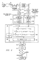
- Fig.2 is a functional block diagram showing the catalyst deterioration judgement section.
- Fig.3 is a flow chart showing an operation for determining deterioration of the catalyst.
- Fig.4 is a graph used to explain the deterioration monitoring zone of the catalytic converter.
- Fig.5 is an explanatory diagram for explaining correlation calculation which is calculated by the cross-correlation computation section.
- Fig.6 is a graph which shows the relation of the deterioration of the catalytic converter and the deterioration index ⁇ i.
- Fig. 7 is a flow chart showing an operation of the pre-catalyst oxygen sensor deterioration judgement section.
- a fuel injection control section 7 includes an air-fuel ratio feedback computation section 8, a fuel injection amount computation section 9, and an output section 10 to thereby control an amount of fuel injection for an engine 1.
- a pre-O 2 sensor or an oxygen sensor (air-fuel ratio sensor) 3 is arranged at the upstream side of a catalytic converter 2.
- the pre-O 2 sensor 3 is a lambda ( ⁇ ) sensor, using, for example, zirconia or titania for the detection element.
- the fuel injection amount computation section 9 calculates a basic amount of injection F0 according to the following equation (1).
- F0 k0Qa/Ne where k0 is a predetermined coefficient.
- the air-fuel ratio feedback computation section 8 samples the output signals of the pre-catalyst oxygen sensor 3 arranged at upstream of the catalytic converter 2 at a predetermined timing.
- the air-fuel ratio feedback computation section 8 calculates a correction coefficient ⁇ in response to the sampled values so that an air-fuel ratio will be a desired value, and supplies the coefficient to the fuel injection amount computation section 9.
- the fuel injection amount computation section 9 calculates an injection amount F based on the basic injection amount F0 in terms of the correction coefficient ⁇ according to the following equation (2).
- F k0Qa/Ne (1+ ⁇ )
- the fuel injection amount computation section 9 then supplies a signal indicating the calculated injection amount F to the output section 10. Then, the output section 10 applies a voltage duty ratio signal corresponding to the injection amount F to fuel injection valves 26.
- An air-fuel ratio at the upstream side of the catalytic converter 2 fluctuates at a value around the stoichiometric air-fuel ratio.
- the fluctuation of the air-fuel ratio in this air-fuel ratio feedback control is used as a test signal for judging deterioration of a catalytic converter. Namely, if the catalytic converter 2 is not deteriorated, the fluctuation of the air-fuel ratio at the downstream side of the catalytic converter 2 is reduced by the oxidation-reduction action of the catalyst. On the other hand, if the catalytic converter 2 is deteriorated, the fluctuation of the air-fuel ratio at the downstream approaches that of the air-fuel ratio at the upstream. Thus, the deterioration is diagnosed by monitoring the similarity of the air-fuel ratio fluctuation at the downstream and upstream sides of the catalytic converter, through, for example, correlation of the output signals of the pre-O 2 sensor and the post-O 2 sensor.
- a deterioration judgment section 11 is provided with a catalyst monitoring zone judgement section 15, a catalyst deterioration judgement section 27, and a pre-O 2 sensor deterioration judgement section 28.
- HPFs high-pass filters
- LPFs low-pass filters
- the catalyst deterioration judgement section 27 includes a correlation factor computation section 18, a sequential deterioration index computation section 16A, a final deterioration index computation section 16B, a comparison section 16C, and a judgement section 17.
- Fig. 1 includes a detrioration judgment section having filters 12A, 12B, 13A, and 13B positioned on the input side of data sampling sections 14A and 14B
- the components are rearranged such that the outputs of data sampling sections 14A and 14B provide the input to high pass filters 12A and 12B, respectively.
- the disturbance of the state of the exhaust gas near the sensor is measured.
- the O 2 sensor deterioration judgement section 28 is provided with a low-pass filter 19, a time-based signal generation section 20, and a data sampling section 21. Furthermore, the O 2 sensor deterioration judgement section 28 includes a difference filter 22, a comparison section 23, and a judgement section 24.
- the output signal Qa from the intake air flow rate sensor 5 and the output signal Ne from the engine speed sensor 6 are supplied to the catalyst monitoring zone judgement section 15.
- the output signal from the catalyst monitoring zone judgement section 15 is then supplied to the data sampling sections 14A and 14B.
- a post-O 2 sensor 4 having the same configuration as the pre-O 2 sensor 3 is arranged at the downstream side of the catalytic converter 2.
- the output signal S4 from the post-O 2 sensor 4 is supplied to the data sampling section 14B via the high-pass filter 12B and the low-pass filter 13B.
- the output signal from the data sampling section 14B is supplied to the judgement section 17 via the correlation factor computation section 18, the sequential deterioration index computation section 16A, the final deterioration index computation section 16B, and the comparison section 16C.
- the output signal S3 from the pre-O 2 sensor 3 is supplied to the data sampling section 14A via the high-pass filter 12A and the low-pass filter 13A.
- the output signal from the data sampling section 14A is supplied to the judgement section 17 via the correlation factor computation section 18, the sequential deterioration index computation section 16A, the final deterioration index computation section 16B, and the comparison section 16C.
- the aforementioned data sampling sections 14A and 14B receive the angular-based signal from a crank angle sensor 25, sampling the data of the signals S3 and S4 at a constant rotation angle of a crank shaft of the engine.
- the output signal S3 from the pre-O 2 sensor 3 is supplied to the data sampling section 21 via the low-pass filter 19.
- This data sampling section 21 receives the time-based signal from the time-based signal generation section 20, sampling the data of the signal S3 at every constant time period.
- the output signal from the data sampling section 21 is supplied to the judgement section 24 via the difference filter 22 and the comparison section 23.
- Fig. 2 is a block diagram showing the detailed structure of the catalyst deterioration judgement section 27.
- Fig. 3 is a flow chart showing an operation for judging deterioration of the catalyst.
- step 100 shown in Fig. 3 the catalyst monitoring zone judgement section 15 judges whether or not the conditions of the engine and the catalytic converter are within a monitoring zone Da of the catalyst on the basis of the intake air flow rate signal Qa and the engine speed signal Ne. Namely, it is judged whether or not the engine speed is higher than or equal to a predetermined rotational speed, and the temperature of the catalytic converter 2 (which is related to the flow rate, as is known to those of skill in the art) is, for example, higher than or equal to 500°C as shown in Fig. 4.
- the catalyst monitoring zone judgement section 15 supplies a sampling commencement signal to the data sampling sections 14A and 14B. The process then proceeds to step 101.
- step 101 the characteristic components of the signals S3 and S4 from the pre- and post-O 2 sensors 3 and 4 are respectively extracted by the high-pass filters 12A and 12B.
- step 102 the characteristic components extracted by the high-pass filters 12A and 12B are supplied to the low-pass filters 13A and 13B, and the noise components of the signals S3 and S4 are removed, respectively.
- step 103 the signals S3 and S4 from which the noise components have been removed are supplied to sampling sections 141A and 141B, and the data of the signals S3 and S4 is sampled at a constant rotation angle of the crank shaft by the sampling sections in accordance with the angular-based signal from the crank angle sensor 25.
- the signals S3 and S4 fluctuate according to engine speed. If these signals S3 and S4 are sampled at a constant rotation angle of the crank shaft, it is possible to suppress the pernicious influence of combustion deterioration (misfire, abnormal combustion etc.) and external disturbance (canister purge etc.), and so on, which are generated in synchronization with engine rotation.
- the signals S3 and S4 sampled in the sampling sections 141A and 141B are temporarily stored in memories 142A and 142B, respectively.
- step 104 the output signal x from the memory 142A and the output signal y from the memory 142B are supplied to a cross-correlation computation section 18B, and the estimations shown in the following equations (3-0 to 3-2) are conducted.
- the suffixes of the signals x anbd y represent sampling timings, and the same suffix represents the same sampling timing.
- the estiamtion interval n is a predetermined period for sufficently calculating the cross-correlation computation.
- the estimation interval n is set to a period corresponding to the period of 200 r.p.m. of the engine.
- the maximum deviation value i between the sampling timings of the signals x and y is larger than or equal to one cycle of the signal S3.
- the time period t shown in Fig. 5 is the delay time (phase) of the output signal S4 of the sensor 4 relative to the output signal S3 of the sensor 3.
- the estimation having the sampling timing deviation nearly equal to the time period t is the maximum value in the above estimates y o to y i .
- the output signal x from the memory 142A is also supplied to an auto-correlation computation section 18A.
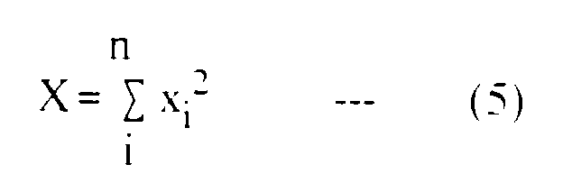
- the auto-correlation computation section 18A executes the calculation shown in the following equation (5).
- the calculated auto-correlation function X and maximum cross-correlation function YM are supplied to the computation section 16A.
- the sequential deterioration index ⁇ i becomes large (approaches 1).
- Fig. 6 the deterioration index ⁇ ia (when the deterioration of the catalytic converter 2 is large) is larger than the deterioration index ⁇ ib (when the deterioration of the catalytic converter 2 is small).
- the deterioration indexes ⁇ i are sequentially calculated in the above-mentioned manner, being supplied to the final deterioration index computation section 16B.
- step 106 the computation section 16B calculates the average value of the calculated deterioration indexes ⁇ i of n times, as shown in equation (7).
- the calculated average is made to be the final deterioration index I of the catalyst converter 2.
- the correction factors based on the various operating conditions of the engine may be taken into consideration.
- correction factors k1 and k2 are previously stored in the memory as map data and the average value of the deterioration indexes ⁇ i are made to the average value from the maximum deterioration index ⁇ i to the n-th deterioration index.
- step 107 the calculated final deterioration index I is supplied to the comparison section 16C, being compared with a predetermined deterioration judgement level ID. If the final deterioration index I is less than the deterioration judgement level ID, the process returns to step 100.
- step 107 when the final deterioration index I is higher than or equal to the deterioration judgement level ID, the catalyst is judged to be deteriorated, and the signal indicating the deterioration is supplied to the judgement section 17. Thereupon, the process proceeds to step 108, the display section (not illustrated) being driven by the judgement section 17 to display the deterioration of the catalytic converter 2.
- step 200 in Fig. 7, the noise component of the output signal S3 from the pre-O 2 sensor 3 is removed by the low-pass filter 19. Then the process proceeds to step 201, the signal S3 is sampled at every constant time period by the data sampling section 21.
- the deterioration of the pre-O 2 sensor 3 is judged on the basis of the magnitude of the incline of the signal wave form of the signal S3. Accordingly, in the deterioration judgement of the pre-O 2 sensor 3, the signal S3 is sampled at every lapse of the constant time period.
- step 201 the sampled signal S3 is supplied to the difference filter 22.
- step 202 the difference data is calculated by the difference filter 22. Namely, the preceding data is subtracted from the current data.
- step 203 the above difference data and the predetermined reference value are compared in the comparison section 23. It is then judged in the judgement section 24 whether the pre-O 2 sensor 3 is deteriorated or not.
- step 204 the process proceeds to step 204, and if the above difference data is larger than the predetermined reference value, the oxygen sensor is judged to be not deteriorated, and the process returns to step 200.
- step 204 if the above difference data is smaller than the predetermined reference value, the O 2 sensor is judged to be deteriorated, and the process proceeds to step 205.
- step 205 the display section (not shown) is driven by the judgement section 24, and it is displayed that the pre-0 2 sensor 3 is deteriorated.
- the deterioration of the catalytic converter 2 is diagnosed based on the fluctuation of the output signal S3 from the pre-O 2 sensor 3 arranged at the upstream side of the catalytic converter 2, and the fluctuation of the output signal S4 from the post-O 2 sensor 4 arranged at the downstream side.
- the characteristic components of the output signals S3 and S4 of the pre- and post-O 2 sensors 3 and 4 are extracted by the high-pass filters 12A and 12B, and the noise components thereof are removed by the low-pass filters 13A and 13B, respectively.
- the signals from which the noise components have been removed are sampled at a constant rotation angle of the crank shaft by the data sampling sections 14A and 14B, and the deterioration of the catalytic converter 2 is judged on the basis of the sampled data. Accordingly, it is possible to diagnose the deterioration of the catalytic converter with a high accuracy in irrespective of an engine speed.
- the output signal S3 of the pre-O 2 sensor 3 is sampled at a constant rotation angle of the crank shaft. Further, in the deterioration judgment of the pre-O 2 sensor 3, the output signal S3 is sampled at every lapse of the constant time period. Namely, when the deterioration of the pre-0 2 sensor 3 is diagnosed on the basis of the magnitude of the incline of the output signal S3, the noise components of the output signal S3 are removed by the low-pass filter 19. The signal from which the noise components have been removed is sampled at every lapse of the constant time period by the data sampling section 21, and the sampled signal is supplied to the difference filter 22. The deterioration of the pre-O 2 sensor 3 is judged on the basis of the data from the difference filter 22. Accordingly, the deterioration of the pre-catalyst oxygen sensor 3 can be diagnosed with a high accuracy.
- an internal combustion engine malfunction diagnosis apparatus capable for diagnosising the deterioration of a catalyst with high accuracy and capable for diagnosising the deterioration of an air-fuel ratio sensor arranged at the upstream side of the catalyst with high accuracy in irrespective of the rotation speed of the engine.
- the signals S3 and S4 from the O 2 sensors 3 and 4 are supplied to the high-pass filters 12A and 12B and the low-pass filters 13A and 13B.
- band-pass filters are used in place of the high-pass filters and the low-pass filters.
- the high-pass filters 12A, 12B and the low-pass filters 13A, 13B, 19 are made of analog circuits constituted by parts such as resistors and capacitors or digital circuits executing filtering process by using software.
- the difference filter 22 is made of analog circuits comprising a delay circuit and a subtraction circuit or a digital circuit executing subtraction of the current data and the data which is temporally just before the current data by using software.
- an oxygen sensor was used as the air-fuel ratio sensor, but the kind of the sensor is not limited to the oxygen sensor, other sensors will occur to those of ordinary skill that are capable of detecting an air-fuel ratio.
- the deterioration of the pre-O 2 sensor 3 is judged.
- the deterioration of the post-O 2 sensor 4 is executed in the same manner as the deterioration judgment of the pre-O 2 sensor 3.
- the deterioration of the catalyst is judged on the basis of the angular-based sampling data of the output signals from the pre- and post-O 2 sensors, and the deterioration of the pre-O 2 sensor is judged on the basis of the time-based sampling data of the output signal from the pre-O 2 sensor.
- the deterioration of other portion of the internal combustion engine is judged.
- the deterioration of other sensors fluctuation factor measuring section) measuring other fluctuation factors (pressure, temperature, flow rate, etc.) are judged.
- the output signal from the intake air flow rate sensor is sampled at a constant rotation angle of the crank shaft, and the pressure of an intake manifold is estimated on the basis of the sampling data. From the difference between the estimated pressure at the operation time of EGR (exhaust gas recirculation) and the pressure actually measured by the pressure sensor, it is judged by the malfunction judgement section whether or not the EGR operation is normal.
- the output signal from the intake air flow rate sensor is sampled at every lapse of the constant time period, and the deterioration of the intake air flow rate sensor is judged by a fluctuation factor measurement section deterioration judgement section having a construction nearly equal to the construction of the O 2 sensor deterioration judgement section 28.
Landscapes
- Engineering & Computer Science (AREA)
- Chemical & Material Sciences (AREA)
- Combustion & Propulsion (AREA)
- Mechanical Engineering (AREA)
- General Engineering & Computer Science (AREA)
- Chemical Kinetics & Catalysis (AREA)
- Exhaust Gas After Treatment (AREA)
- Electrical Control Of Air Or Fuel Supplied To Internal-Combustion Engine (AREA)
- Testing Of Engines (AREA)
Description
- 1
- engine
- 2
- catalytic converter
- 3
- pre-02 sensor
- 4
- post-O2 sensor
- 5
- intake air flow sensor
- 6
- engine speed sensor
- 7
- fuel injection control section
- 8
- air-fuel ratio feedback computation section
- 9
- fuel injection amount computation section
- 10
- output section
- 11
- deterioration judgment section
- 12A, 12B
- deterioration judgment section
- 13A, 13B
- low-pass filter
- 14A, 14B
- data sampling section
- 15
- catalyst monitoring zone judgement section
- 16A
- sequential deterioration index computation section
- 16B
- final deterioration index computation section
- 16C
- comparison section
- 17
- judgement section
- 18
- correlation factor computation section
- 18A
- auto-correlation computation section
- 18B
- cross-correlation computation section
- 18C
- cross-correlation function computation section
- 19
- low-pass filter
- 20
- time-based signal generating section
- 21
- data sampling section
- 22
- difference filter
- 23
- comparison section
- 24
- judgement section
- 25
- crank angle sensor
- 26
- fuel injector
- 27
- catalyst deterioration judgement section
- 28
- O2 sensor deterioration judgement section
- I
- final deterioration index
- Ne
- engine speed
- Qa
- intake air flow rate
- S3
- output signal of pre-O2 sensor
- S4
- output signal of post-O2 sensor
- X
- self-correlation function
- Y
- cross-correlation function
- Φi
- sequential deterioration index



Claims (13)
- A malfunction diagnosis apparatus for an internal combustion engine comprising:characterized in that said apparatus further comprises:a fluctuation factor state measurement sensor (3,4);an angular-based data sampler (14A, 14B) for sampling data of an output signal (S3, S4) from said fluctuation factor state measurement sensor (3,4) at a rate dependent on engine speed; andmalfunction judgement means (11) for judging a malfunction of a function of said internal combustion engine;a time-based data sampler (20, 21) for sampling an output signal from said fluctuation factor state measurement sensor (3, 4) at every lapse of a predetermined constant time; andmeans for determining a malfunction monitoring zone (100) constituted by predetermined conditions; and whereinsaid malfunction judgement means (11) is responsive to said angular-based data sampler (14A, 14B) and said time-based data sampler (20, 21) and wherein said malfunction judgement means (11) judges a malfunction of a function of said internal combustion engine when said malfunction monitoring zone (100) is determined.
- A malfunction diagnosis apparatus according to claim 1 characterized in that said malfunction judgement means (11) judges a malfunction of a function of said internal combustion engine on the basis of data from at least one sampler which is selected from said angular based data sampler and said time-based data sampler in accordance with a malfunction to be diagnosed, when said malfunction monitoring zone (100) is determined.
- A malfunction diagnosis apparatus according to claim 1 or claim 2, further comprising a fluctuation factor state measurement sensor deterioration judgement means (28) for judging deterioration of said fluctuation factor state measurement sensor (3, 4) on the basis of data sampled by said time-based data sampler (20, 21).
- A malfunction diagnosis apparatus according to claim 1 or claim 2, further comprising a catalyst deterioration judgement means for judging deterioration of a catalyst of said internal combustion engine on the basis of data sampled by said angular-based data sampler (14A, 14B).
- A malfunction diagnosis apparatus according to any preceding claim, characterized in that said fluctuation factor state measurement sensor (3, 4) comprises:a pre-catalyst air-fuel ratio sensor (3) arranged at an upstream side of a catalyst (2) of said internal combustion engine to detect an air-fuel ratio of exhaust gas of said internal combustion engine at an upstream side of said catalyst (2); anda post catalyst air-fuel ratio sensor (4) arranged at a down stream side of said catalyst (2) to detect an air-fuel ratio of exhaust gas at a downstream side of said catalyst (2).
- A malfunction diagnosis apparatus according to claim 5, further comprising a noise removal means (12A, 13A) for removing noise components from the output signal of said pre-catalyst air-fuel ratio sensor (3).
- A malfunction diagnosis apparatus according to any preceding claim, further comprising:an engine speed sensor (6) for determining a rotational speed of said internal combustion engine, andan intake air flow rate sensor (5) for detecting an intake air flow rate of said internal combustion engine,wherein a catalyst monitoring zone judgement section (15) judges that the conditions of said catalyst monitoring zone are satisfied when:the rotational speed of said internal combustion engine is higher than or equal to a predetermined rotational speed value, anda catalyst temperature estimated from the rotational speed and intake air flow rate of said internal combustion engine is higher than or equal to a predetermined temperature.
- A malfunction diagnosis apparatus according to any preceding claim, characterized in that said fluctuation factor state measurement sensor (3, 4) comprises:a pre-catalyst air-fuel ratio sensor (3) arranged at an upstream side of a catalyst (2) of said internal combustion engine to detect an air-fuel ratio of exhaust gas of said internal combustion engine at an upstream side of said catalyst (2); anda post catalyst air-fuel ratio sensor (4) arranged at a down stream side of said catalyst (2) to detect an air-fuel ratio of exhaust gas at a downstream side of said catalyst (2);and that a catalytic converter deterioration judgement section (27) being part of said deterioration judgement section (11) includes:a correlation function computation section (18) for calculating cross-correlation functions of the output signals of said pre- and post-catalyst air-fuel ratio sensors (3, 4) and auto-correlation functions of the output signals of said pre-catalyst air-fuel ratio sensor (3), wherein said output signals are obtained from said angular-based data sampler (14A, 14B);a sequential deterioration index computation section (16A) for calculating a sequential deterioration index which is proportional to a ratio of a value of said cross-correlation functions and a value of said auto-correlation functions;a final deterioration index computation section (16B) for calculating an average of a predetermined number of sequential deterioration indexes, and for calculating a value on the basis of the calculated average value as a final deterioration index;a comparison section (16C) for comparing said final deterioration index with a predetermined reference deterioration index; anda judgement section (17) for judging deterioration of said catalyst (2) on the basis of an output from said comparison section (16C).
- A malfunction diagnosis apparatus according to any preceding claim, characterized in that said angular-based sampler (14A, 14B) samples data no more than once per engine revolution and only at the same engine revolution angle for each sampling event.
- A malfunction diagnosis apparatus according to any preceding claim, characterized in that said every lapse of said predetermined constant time is a constant time interval.
- A malfunction diagnosis apparatus according to any preceding claim. characterized in that said angular-based data sampler (14A, 14B) comprises means for sampling upon a rotation of an engine crank shaft through a constant rotation angle.
- A malfunction diagnosis apparatus for an internal combustion engine comprising:characterized bya fluctuation factor state measurement sensor (3,4);an angular-based data sampler (14A, 14B) for sampling data of an output signal (S3, S4) from said fluctuation factor state measurement sensor (3,4) at a rate dependent on engine speed; andmalfunction judgement means (11) for judging a malfunction of a function of said internal combustion engine;a time-based data sampler (20, 21) which samples an output signal from said fluctuation factor state measurement sensor (3, 4) at every lapse of a predetermined constant time; andsaid malfunction judgement means (11) judging a malfunction of a function of said internal combustion engine on the basis of said data sampled by said angular-based data sampler (14A, 14B), and judging a malfunction of said fluctuation factor state measurement sensor (3, 4) on the basis of said time-based data sampler (20, 21).
- A process for diagnosing the deterioration of a function of an internal combustion engine comprising:characterized bysampling data of an output signal (S3, S4) of a fluctuation factor state measurement sensor (3, 4) on an angular basis at a rate dependent on engine speed;judging a malfunction of a function of said internal combustion engine,sampling data of an output signal (S3, S4) from said fluctuation factor state measurement sensor (3, 4) at every lapse of a predetermined constant time;determining a malfunction monitoring zone (100) when predetermined conditions of said monitoring zone (100) are satisfied; andjudging a malfunction of a function of said internal combustion engine when said malfunction monitoring zone is determined on the basis of data from said angular-based data sampler and said time-based data sampler.
Applications Claiming Priority (2)
| Application Number | Priority Date | Filing Date | Title |
|---|---|---|---|
| JP22361393A JP3169298B2 (en) | 1993-09-08 | 1993-09-08 | Internal combustion engine failure diagnosis device |
| JP223613/93 | 1993-09-08 |
Publications (2)
| Publication Number | Publication Date |
|---|---|
| EP0641920A1 EP0641920A1 (en) | 1995-03-08 |
| EP0641920B1 true EP0641920B1 (en) | 1998-12-02 |
Family
ID=16800949
Family Applications (1)
| Application Number | Title | Priority Date | Filing Date |
|---|---|---|---|
| EP94114042A Expired - Lifetime EP0641920B1 (en) | 1993-09-08 | 1994-09-07 | Malfunction diagnosis apparatus for internal combustion engine |
Country Status (4)
| Country | Link |
|---|---|
| US (1) | US5557933A (en) |
| EP (1) | EP0641920B1 (en) |
| JP (1) | JP3169298B2 (en) |
| DE (1) | DE69414941T2 (en) |
Families Citing this family (33)
| Publication number | Priority date | Publication date | Assignee | Title |
|---|---|---|---|---|
| US5657625A (en) * | 1994-06-17 | 1997-08-19 | Mitsubishi Jidosha Kogyo Kabushiki Kaisha | Apparatus and method for internal combustion engine control |
| SE510029C2 (en) * | 1995-10-03 | 1999-04-12 | Volvo Ab | Diagnostic system in a motor operating system as well as a diagnostic function module (DF module) in a motor operating system |
| AU1282199A (en) * | 1997-11-14 | 1999-06-07 | Engelhard Corporation | Vehicular on-board monitoring system sensing combined hc/nox emissions for catalytic converter evaluation |
| EP1106800B1 (en) * | 1998-07-17 | 2007-10-24 | Honda Giken Kogyo Kabushiki Kaisha | Method of judging deterioration of emission gas control catalyst device |
| US6253542B1 (en) * | 1999-08-17 | 2001-07-03 | Ford Global Technologies, Inc. | Air-fuel ratio feedback control |
| JP3688533B2 (en) * | 1999-11-12 | 2005-08-31 | 本田技研工業株式会社 | Degradation state evaluation method of exhaust gas purification catalyst device |
| JP3967524B2 (en) * | 1999-12-22 | 2007-08-29 | 本田技研工業株式会社 | Air-fuel ratio control device for internal combustion engine |
| JP4312325B2 (en) * | 1999-12-28 | 2009-08-12 | 本田技研工業株式会社 | Degradation state evaluation method of exhaust gas purification catalyst device |
| DE10017931A1 (en) | 2000-04-11 | 2001-12-06 | Siemens Ag | Method for diagnosing an exhaust gas purification system of a lambda-controlled internal combustion engine |
| DE10036154B4 (en) * | 2000-07-25 | 2015-11-26 | Volkswagen Ag | Method for checking a fuel pressure control system |
| DE10038444B4 (en) * | 2000-08-07 | 2014-07-31 | Volkswagen Ag | Method for checking a fuel injection system |
| US6453663B1 (en) * | 2001-08-16 | 2002-09-24 | Ford Global Technologies, Inc | NOx sensor monitoring |
| DE10201329B4 (en) * | 2002-01-15 | 2004-08-26 | Siemens Ag | Method and device for determining an internal temperature in a catalytic converter |
| DE10300593A1 (en) * | 2003-01-10 | 2004-07-22 | Robert Bosch Gmbh | Operating method for a motor vehicle's internal combustion engine has exhaust gas re-circulation to feed exhaust gas from an exhaust gas branch with an adjusting element into a suction pipe |
| JP3927163B2 (en) * | 2003-10-21 | 2007-06-06 | 本田技研工業株式会社 | Deterioration detection system for internal combustion engine purifier using nonlinear filter |
| JP4320778B2 (en) * | 2004-08-23 | 2009-08-26 | 株式会社デンソー | Air-fuel ratio sensor abnormality diagnosis device |
| JP4607541B2 (en) * | 2004-10-26 | 2011-01-05 | 独立行政法人交通安全環境研究所 | Three-way catalyst deterioration diagnosis method |
| JP4832068B2 (en) * | 2005-12-05 | 2011-12-07 | トヨタ自動車株式会社 | Air-fuel ratio control device |
| JP4802116B2 (en) * | 2007-02-21 | 2011-10-26 | 日本特殊陶業株式会社 | Gas sensor abnormality diagnosis method, gas sensor abnormality diagnosis device |
| JP4874918B2 (en) * | 2007-10-01 | 2012-02-15 | 日本特殊陶業株式会社 | Gas sensor abnormality diagnosis method, gas sensor abnormality diagnosis device |
| JP4747156B2 (en) * | 2007-12-06 | 2011-08-17 | 日立オートモティブシステムズ株式会社 | Exhaust purification device diagnostic device |
| JP5331753B2 (en) * | 2010-06-04 | 2013-10-30 | 日立オートモティブシステムズ株式会社 | Engine control device |
| US9279406B2 (en) | 2012-06-22 | 2016-03-08 | Illinois Tool Works, Inc. | System and method for analyzing carbon build up in an engine |
| JP2017528783A (en) | 2014-06-06 | 2017-09-28 | シーティーエス・コーポレーションCts Corporation | High frequency process sensing, control and diagnostic network |
| CN112362973A (en) | 2014-06-06 | 2021-02-12 | 滤波器感知技术有限公司 | Radio frequency state variable measurement system and method |
| CN106794409A (en) * | 2014-10-20 | 2017-05-31 | 滤波器感知技术有限公司 | Filter retentate is analyzed and diagnosed |
| US10118119B2 (en) | 2015-06-08 | 2018-11-06 | Cts Corporation | Radio frequency process sensing, control, and diagnostics network and system |
| US10799826B2 (en) | 2015-06-08 | 2020-10-13 | Cts Corporation | Radio frequency process sensing, control, and diagnostics network and system |
| DE102016200721A1 (en) * | 2016-01-20 | 2017-07-20 | Robert Bosch Gmbh | Method for monitoring NOx sensors |
| WO2017180466A1 (en) | 2016-04-11 | 2017-10-19 | Cts Corporation | Radio frequency system and method for monitoring engine-out exhaust constituents |
| WO2019143595A1 (en) | 2018-01-16 | 2019-07-25 | Cts Corporation | Radio frequency sensor system incorporating machine learning system and method |
| NL2023020B1 (en) * | 2019-04-29 | 2020-11-05 | Daf Trucks Nv | OBD Sensor response diagnostics and anti tamper device |
| FR3096085B1 (en) * | 2019-05-16 | 2021-05-28 | Continental Automotive Gmbh | Lambda probe control method |
Citations (1)
| Publication number | Priority date | Publication date | Assignee | Title |
|---|---|---|---|---|
| US4255789A (en) * | 1978-02-27 | 1981-03-10 | The Bendix Corporation | Microprocessor-based electronic engine control system |
Family Cites Families (10)
| Publication number | Priority date | Publication date | Assignee | Title |
|---|---|---|---|---|
| JP2526640B2 (en) * | 1988-07-20 | 1996-08-21 | トヨタ自動車株式会社 | Catalyst deterioration determination device for internal combustion engine |
| JPH0718368B2 (en) * | 1990-04-02 | 1995-03-06 | トヨタ自動車株式会社 | Catalyst deterioration detection device for internal combustion engine |
| JP2807769B2 (en) * | 1990-08-30 | 1998-10-08 | 本田技研工業株式会社 | Fault diagnosis method for control device of internal combustion engine |
| JP3186076B2 (en) * | 1991-03-20 | 2001-07-11 | 株式会社日立製作所 | Estimation method of catalyst conversion efficiency for exhaust gas purification of internal combustion engine |
| US5138874A (en) * | 1991-07-01 | 1992-08-18 | General Motors Corporation | Diagnostic system for detecting faults in engine air intake check valves |
| US5335539A (en) * | 1991-08-30 | 1994-08-09 | Ford Motor Company | Onboard detection of oxygen sensor switch rate for determining air/fuel ratio control system failure |
| JP3303981B2 (en) * | 1991-12-20 | 2002-07-22 | 株式会社日立製作所 | Diagnosis device for engine exhaust gas purification device |
| DE4234420C1 (en) * | 1992-10-13 | 1994-04-14 | Porsche Ag | Controlling operation of IC engine of motor vehicle - using stored characteristic addressed by engine operating point for calculating temp. of engine exhaust component |
| US5305635A (en) * | 1993-04-02 | 1994-04-26 | Ford Motor Company | System and method for filtering a misfire detecting data stream to yield optimum measurement of misfire rate |
| US5394744A (en) * | 1994-01-05 | 1995-03-07 | Ford Motor Company | Fault detection using averaging filter with variable response time |
-
1993
- 1993-09-08 JP JP22361393A patent/JP3169298B2/en not_active Expired - Lifetime
-
1994
- 1994-09-07 EP EP94114042A patent/EP0641920B1/en not_active Expired - Lifetime
- 1994-09-07 DE DE69414941T patent/DE69414941T2/en not_active Expired - Fee Related
- 1994-09-08 US US08/302,409 patent/US5557933A/en not_active Expired - Lifetime
Patent Citations (1)
| Publication number | Priority date | Publication date | Assignee | Title |
|---|---|---|---|---|
| US4255789A (en) * | 1978-02-27 | 1981-03-10 | The Bendix Corporation | Microprocessor-based electronic engine control system |
Also Published As
| Publication number | Publication date |
|---|---|
| JP3169298B2 (en) | 2001-05-21 |
| US5557933A (en) | 1996-09-24 |
| DE69414941T2 (en) | 1999-08-05 |
| DE69414941D1 (en) | 1999-01-14 |
| EP0641920A1 (en) | 1995-03-08 |
| JPH0777481A (en) | 1995-03-20 |
Similar Documents
| Publication | Publication Date | Title |
|---|---|---|
| US5557933A (en) | Malfunction diagnosis apparatus for internal combustion engine | |
| KR100232380B1 (en) | System for diagnosing engine exhaust gas purifying device and system for diagnosing sensor | |
| KR100405091B1 (en) | Diagnostic device of exhaust gas purification device for internal combustion engine | |
| EP0626507B1 (en) | System for diagnosing deterioration of catalyst | |
| US5331560A (en) | Apparatus and method for self diagnosing engine component controlling systems according to predetermined levels of priority | |
| EP0667446B1 (en) | Method and apparatus for diagnosing engine exhaust gas purification system | |
| JP4490913B2 (en) | Method for inspecting at least three sensors for detecting measurement variables within the range of an internal combustion engine | |
| EP0677165B1 (en) | System to determine engine misfire | |
| EP2037090A1 (en) | Pm trapper failure detecting system | |
| US20080229730A1 (en) | NOx TRAPPING CATALYTIC CONVERTER DIAGNOSTIC APPARATUS | |
| JP2004526959A (en) | Method and apparatus for monitoring a sensor | |
| US6944531B2 (en) | Air flow sensor failure determination apparatus and method | |
| US20060260295A1 (en) | Method and device for diagnosing a reading | |
| JP2003328823A (en) | Device that detects failure of exhaust gas sensor | |
| JPH05141227A (en) | Control device for internal combustion engine provided with exhaust gas purifying catalyser and method and device for diagnosing deterioration of this catalyser | |
| US20020139109A1 (en) | Catalyst deterioration detecting system for an automobile | |
| US6968682B1 (en) | Method and device for controlling an internal combustion engine with an exhaust treatment system | |
| JPH01206251A (en) | Apparatus for processing measuring signal for air/fuel ratio sensor | |
| JP3663921B2 (en) | Oxygen sensor diagnostic device | |
| JP3564064B2 (en) | Diagnosis device for engine exhaust gas purification device | |
| JPH05263626A (en) | Diagnosis device for engine exhaust emission control device | |
| RU2775951C2 (en) | Method and device for determining particulate filter presence and performance | |
| JP4037485B2 (en) | Engine catalyst deterioration diagnosis device | |
| JP3442819B2 (en) | Internal combustion engine failure diagnosis device | |
| JP2004232602A (en) | Engine catalyst deterioration diagnosis device |
Legal Events
| Date | Code | Title | Description |
|---|---|---|---|
| PUAI | Public reference made under article 153(3) epc to a published international application that has entered the european phase |
Free format text: ORIGINAL CODE: 0009012 |
|
| 17P | Request for examination filed |
Effective date: 19940907 |
|
| AK | Designated contracting states |
Kind code of ref document: A1 Designated state(s): DE GB IT |
|
| 17Q | First examination report despatched |
Effective date: 19960209 |
|
| GRAG | Despatch of communication of intention to grant |
Free format text: ORIGINAL CODE: EPIDOS AGRA |
|
| GRAG | Despatch of communication of intention to grant |
Free format text: ORIGINAL CODE: EPIDOS AGRA |
|
| GRAH | Despatch of communication of intention to grant a patent |
Free format text: ORIGINAL CODE: EPIDOS IGRA |
|
| GRAH | Despatch of communication of intention to grant a patent |
Free format text: ORIGINAL CODE: EPIDOS IGRA |
|
| GRAA | (expected) grant |
Free format text: ORIGINAL CODE: 0009210 |
|
| RAP1 | Party data changed (applicant data changed or rights of an application transferred) |
Owner name: HITACHI CAR ENGINEERING CO., LTD. Owner name: HITACHI, LTD. |
|
| AK | Designated contracting states |
Kind code of ref document: B1 Designated state(s): DE GB IT |
|
| REF | Corresponds to: |
Ref document number: 69414941 Country of ref document: DE Date of ref document: 19990114 |
|
| ITF | It: translation for a ep patent filed | ||
| PLBE | No opposition filed within time limit |
Free format text: ORIGINAL CODE: 0009261 |
|
| STAA | Information on the status of an ep patent application or granted ep patent |
Free format text: STATUS: NO OPPOSITION FILED WITHIN TIME LIMIT |
|
| 26N | No opposition filed | ||
| REG | Reference to a national code |
Ref country code: GB Ref legal event code: IF02 |
|
| PG25 | Lapsed in a contracting state [announced via postgrant information from national office to epo] |
Ref country code: IT Free format text: LAPSE BECAUSE OF NON-PAYMENT OF DUE FEES;WARNING: LAPSES OF ITALIAN PATENTS WITH EFFECTIVE DATE BEFORE 2007 MAY HAVE OCCURRED AT ANY TIME BEFORE 2007. THE CORRECT EFFECTIVE DATE MAY BE DIFFERENT FROM THE ONE RECORDED. Effective date: 20050907 |
|
| PGFP | Annual fee paid to national office [announced via postgrant information from national office to epo] |
Ref country code: GB Payment date: 20080820 Year of fee payment: 15 |
|
| PGFP | Annual fee paid to national office [announced via postgrant information from national office to epo] |
Ref country code: DE Payment date: 20080908 Year of fee payment: 15 |
|
| GBPC | Gb: european patent ceased through non-payment of renewal fee |
Effective date: 20090907 |
|
| PG25 | Lapsed in a contracting state [announced via postgrant information from national office to epo] |
Ref country code: DE Free format text: LAPSE BECAUSE OF NON-PAYMENT OF DUE FEES Effective date: 20100401 |
|
| PG25 | Lapsed in a contracting state [announced via postgrant information from national office to epo] |
Ref country code: GB Free format text: LAPSE BECAUSE OF NON-PAYMENT OF DUE FEES Effective date: 20090907 |